Table of Contents
Advertisement
Quick Links
Declaration of Conformity—Mercury Diesel Sterndrive (VW)
This sterndrive engine when installed in accordance to Mercury Marine's instructions complies with the requirements of
the following directives by meeting the associated standards, as amended:
Recreational Craft Propulsion Engines with the Requirements of Directive 94/25/EC as amended by 2003/44/EC
Name of engine manufacturer: Volkswagen Antriebssysteme
Address: HMA‑E/1, PO 7962, Industriestraße Nord
Town: Salzgitter
Name of Authorized Representative: Brunswick Marine in EMEA Inc.
Address: Parc Industriel de Petit‑Rechain
Town: Verviers
Name of Notified Body for exhaust emission assessment: International Marine Certification Institute (IMCI)
Address: Rue Abbé Cuypers 3
Town: Bruxelles
Name of Notified Body for noise emission assessment: International Marine Certification Institute (IMCI)
Address: Rue Abbé Cuypers 3
Town: Bruxelles
Conformity assessment module used for exhaust emissions:
Conformity assessment module used for noise emissions:
Other Community Directives applied: Electromagnetic Compatibility Directive 2004/108/EC
Description of Engines and Essential Requirements
Engine Type
☒ z or sterndrive with integral exhaust
Identification of Engines Covered by This Declaration of Conformity
Name of engine model or engine
family:
TDI 2.5L 100/120
TDI 2.5L 140/150/165
TDI 3.0L 225/230/265
TDI 4.2L 285/350
Essential requirements
Annex 1.B—Exhaust Emissions
B.1 engine identification
B.2 exhaust emission requirements
B.3 durability
B.4 owner's manual
Annex 1.C—Noise Emissions
C.1 Noise emission levels
C.2 Owner's manual
Post Code: 38231
Post Code: 4800
Post Code: B‑1040
Post Code: B‑1040
Unique engine identification number(s) or engine
family code(s)
TDI 100‑5/TDI 100‑5 SE
TDI 150‑5/TDI 150‑5 D/TDI 165‑5
TDI 225‑6/TDI 230‑6/TDI 265‑6
TDI 285‑8/TDI 350‑8
Other normative
Standards
document/ method
☐
☒*
☐
☒
☒*
☐
Country: Germany
Country: Belgium
Country: Belgium
Country: Belgium
☒ B+C
☐ B+D
A ☐
Fuel Type
Combustion Cycle
☒ Diesel
☒ 4 stroke
Technical file
☐
☒
☐
☐
☐
☒
☐
☐
☐
☐
☒
☐
ID Number: 0609
ID Number: 0609
☐ B+E
☐ B+F
☐ G ☐ H
Aa ☒
G ☐ H ☐
EC Type–examination
certificate or type‑approval
certificate number
EXVWM003
EXVWM004
EXVWM007
EXVWM008
Please specify in more detail
(* = mandatory standard)
*EN ISO 8178‑1:1996
ISO 8665:1995
*EN ISO 14509
Owner's manual
Advertisement
Table of Contents
Troubleshooting

Subscribe to Our Youtube Channel
Related Manuals for MerCruiser Sterndrive TDI 3.0L


Summary of Contents for MerCruiser Sterndrive TDI 3.0L
- Page 1 Declaration of Conformity—Mercury Diesel Sterndrive (VW) This sterndrive engine when installed in accordance to Mercury Marine's instructions complies with the requirements of the following directives by meeting the associated standards, as amended: Recreational Craft Propulsion Engines with the Requirements of Directive 94/25/EC as amended by 2003/44/EC Name of engine manufacturer: Volkswagen Antriebssysteme Address: HMA‑E/1, PO 7962, Industriestraße Nord Town: Salzgitter...
- Page 2 Mercury Marine, Fond du Lac, Wisconsin, USA. Printed in USA. © 2012, Mercury Marine Mercury, Mercury Marine, MerCruiser, Mercury MerCruiser, Mercury Racing, Mercury Precision Parts, Mercury Propellers, Mariner, Quicksilver, Alpha, Axius, Bravo One, Bravo Two, Bravo Three, K‑Planes, MerCathode, OptiMax, Precision Pilot, Pro Max, SeaCore, Skyhook, SmartCraft, Sport‑Jet, Total Command, Verado, VesselView, Zero Effort, Zeus, #1 On The Water, M...
-
Page 3: Read This Manual Thoroughly
Thank you for purchasing one of our Mercury Diesel products. We sincerely hope your boating will be pleasant! Mercury Marine Warranty Message The product you have purchased comes with a limited warranty from Mercury Marine; the terms of the warranty are set forth in the Warranty Sections of this manual. -
Page 5: Table Of Contents
Transfer of Warranty............7 What is Covered............. 3 Warranty Policy—Australia and New Zealand......8 Duration of Coverage............. 3 MerCruiser Limited Warranty–Australia and New Zealand High‑Output Rating............3 Policy.................. 8 Conditions That Must Be Met to Obtain Warranty What is Covered............. 8 Coverage................ - Page 6 Section 3 - On The Water Safe Boating Suggestions............30 While Boat Is Stationary..........36 Carbon Monoxide Exposure........... 31 High‑Speed and High‑Performance........ 37 Be Alert To Carbon Monoxide Poisoning......31 Passenger Safety In Pontoon Boats And Deck Boats..37 Stay Clear of Exhaust Areas..........31 Boats Having An Open Front Deck......
- Page 7 Power‑Assisted Steering Fluid..........64 Cleaning and Inspection..........76 Checking................64 Installation..............77 Filling.................. 64 Sterndrive Corrosion Protection Components....78 Changing................65 Anodes and MerCathode System Locations....78 Engine Coolant................ 65 Continuity Circuit—Bravo Sterndrive........ 80 Checking................65 MerCathode..............82 Filling.................. 66 Painting Your Power Package..........
- Page 8 Customer Service Literature..........109 Andre språk..............109 English Language............109 Outros Idiomas............... 110 Other Languages............109 Otros idiomas..............110 Andre sprog..............109 Andra språk..............110 Andere talen..............109 Allej glþssej..............110 Muut kielet..............109 Ordering Literature............... 110 Autres langues..............109 United States and Canada..........
-
Page 9: Section 1 - Warranty
Transfer of Warranty............7 What is Covered ............3 Warranty Policy—Australia and New Zealand......8 Duration of Coverage ..........3 MerCruiser Limited Warranty–Australia and New Zealand High‑Output Rating ..........3 Policy................8 Conditions That Must Be Met to Obtain Warranty What is Covered ............ -
Page 10: Warranty Information
Section 1 - Warranty Warranty Information Warranty Registration United States and Canada To be eligible for warranty coverage, the product must be registered with Mercury Marine. At the time of sale, the dealer should complete the warranty registration and immediately submit it to Mercury Marine via MercNET, E‑mail, or mail. Upon receipt of this warranty registration, Mercury Marine will record the registration. -
Page 11: Warranty Policy-Diesel Models
Section 1 - Warranty For products purchased outside the United States and Canada, contact the distributor in your country, or the Marine Power Service Center closest to you. Warranty Policy–Diesel Models High‑Output Recreational Use Worldwide Limited Warranty What is Covered Mercury Marine warrants each new engine/drive package (Product) to be free of defects in material and workmanship during the period described following. -
Page 12: What Is Not Covered
Section 1 - Warranty What Is Not Covered This limited warranty does not cover the following: • Routine maintenance items • Adjustments • Normal wear and tear • Damage caused by abuse • Abnormal use • Use of a propeller or gear ratio that does not allow the engine to run in its recommended RPM range (see the Operation, Maintenance &... -
Page 13: Duration Of Coverage
Section 1 - Warranty Duration of Coverage The warranty period begins on the date the product is first sold to a light‑duty commercial‑use retail purchaser or the date on which the product is first put into service, whichever occurs first. This Limited Warranty provides coverage for one (1) year or 500 hours of use, whichever occurs first. -
Page 14: 3-Year Limited Warranty Against Corrosion-Diesel Models (Recreational Use Only)
Section 1 - Warranty • Accident • Submersion • Improper installation (proper installation specifications and techniques are set forth in the installation instructions for the product) • Improper service • Use of an accessory or part that was not manufactured or sold by Mercury Marine and that damages the Mercury product •... -
Page 15: What Mercury Will Do
Section 1 - Warranty What Mercury Will Do Mercury's sole and exclusive obligation under this warranty is limited to, at our option, repairing a corroded part, replacing such part or parts with new or Mercury Marine certified re‑manufactured parts, or refunding the purchase price of the Mercury product. -
Page 16: Warranty Policy-Australia And New Zealand
Section 1 - Warranty Warranty Policy—Australia and New Zealand MerCruiser Limited Warranty–Australia and New Zealand Policy This Limited Warranty is given by Marine Power International Pty Ltd ACN 003 100 007 of 41–71 Bessemer Drive, Dandenong South, Victoria 3175 Australia (telephone (61) (3) 9791 5822), email: merc_info@mermarine.com. -
Page 17: Conditions That Must Be Met To Obtain Warranty Coverage
Section 1 - Warranty • Purchased from an insurance company that obtained the product as a result of an insurance claim • Purchased from a salvage yard • Repossession from a retail customer • Purchased at an auction Conditions That Must Be Met to Obtain Warranty Coverage Warranty coverage under this Limited Warranty is available only to retail customers that purchase from a dealer authorized by Mercury Marine to distribute the product in the country in which the sale occurred, and then only after the predelivery inspection process specified by Mercury Marine is completed and documented. -
Page 18: Expense Of Claiming This Limited Warranty
Section 1 - Warranty • Alteration or removal of parts • Water entering the engine through the fuel intake, air intake, or exhaust system or damage to the product from insufficient cooling water caused by blockage of the cooling system by a foreign body •... -
Page 19: Section 2 - Getting To Know Your Power Package
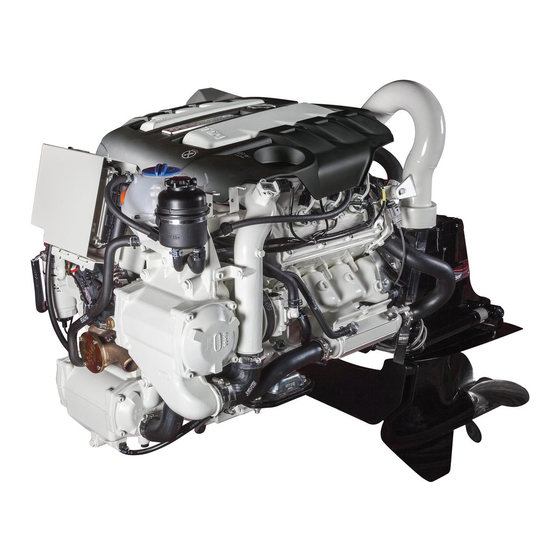
Section 2 - Getting to Know Your Power Package Section 2 - Getting to Know Your Power Package Table of Contents Engine Component List............12 Emergency Stop Switch ........21 3.0 Liter TDI Front View Components......12 Remote Control.............. 22 3.0 Liter TDI Starboard View Components.... -
Page 20: Engine Component List
Section 2 - Getting to Know Your Power Package Engine Component List 3.0 Liter TDI Front View Components 50725 Engine oil dipstick Engine coolant expansion tank Power steering oil reservoir Charge air cooler (intercooler) Sacrificial anode Seawater inlet connection Seawater pump Heat exchanger Engine oil drain hose Oil extraction pump... -
Page 21: 3.0 Liter Tdi Starboard View Components
Section 2 - Getting to Know Your Power Package 3.0 Liter TDI Starboard View Components 50726 Oil extraction pump button Central electrical unit housing and shift bracket Manual fuel primer Fuel supply connection Fuel filter with water sensor Engine oil sump Starter Air filter Turbocharger... -
Page 22: 3.0 Liter Tdi Port View Components
Section 2 - Getting to Know Your Power Package 3.0 Liter TDI Port View Components 50729 Engine cover Exhaust pipe Bell housing Power steering connection Power steering/gearbox oil cooler Engine speed sender Gearbox neutral switch connection Optional accessory connection Power steering pump Throttle position sender Page 14 90-8M0070851... -
Page 23: Features And Controls
Section 2 - Getting to Know Your Power Package Features and Controls 3.0 Liter Engine Features 50793 The Mercury Diesel 3.0 Liter 6 cylinder engine has the following features: • Four‑stroke diesel engine • Common‑rail direct injection • 6 cylinder (90° V angle) •... - Page 24 Section 2 - Getting to Know Your Power Package Accidental ejections can also occur from: • poor operating practices • sitting on the seat or gunwale at planing speeds • standing at planing speeds • operating at planing speeds in shallow or obstacle infested waters •...
-
Page 25: Instrumentation-3.0 Liter Tdi
Section 2 - Getting to Know Your Power Package Instrumentation—3.0 Liter TDI Standard Instrumentation Panel The following is the standard instrumentation package. The owner and operator should be familiar with all the instruments and their functions on the boat. Because of the large variety of instrumentation and manufacturers, you should have your boat dealer explain the gauges and normal readings that will appear on your boat. -
Page 26: Engine Monitoring Features Of The Information Panel
Section 2 - Getting to Know Your Power Package Engine Monitoring Features of the Information Panel 50462 Reference Indicator Lamp Function Used in conjunction with the tachometer to display engine operating Information panel conditions Indicates a problem with the engine if the lamp illuminates while the engine is operating. -
Page 27: Voltmeter Gauge
If the V‑belt is in good condition, check for loose connections on the alternator • If all connections appear to be proper, contact your authorized MerCruiser service center as the problem is likely in the alternator or alternator regulator IMPORTANT: Do not operate the engine with the battery disconnected as the alternator will be damaged. Do not operate the engine with alternator ribbed belt disconnected as the front vibration damper will be damaged. -
Page 28: Ignition Lock Switch
Section 2 - Getting to Know Your Power Package IMPORTANT: The oil pressure warning icon is not an oil level display. Engine oil level should be checked at regular intervals and before each engine start. Ignition Lock Switch The ignition lock switch is used in conjunction with an ignition key to start the engine. The ignition lock switch has three positions. -
Page 29: Optional Instrumentation Panel
Section 2 - Getting to Know Your Power Package Optional Instrumentation Panel c d e f 50519 Reference Feature Function Instrumentation panel Alternative to individual gauges Tachometer Indicates engine operating RPM Coolant temperature warning Indicates excessive engine coolant temperature lamp Engine control unit warning lamp Indicates a fault has occurred and is being stored in the control unit memory... -
Page 30: Remote Control
Section 2 - Getting to Know Your Power Package Remote Control Remote Control Function Operation of the throttle and shift are controlled by the movement of the control handle. Push the control handle forward from neutral with a quick firm motion to the first detent for forward gear. Continue pushing forward to increase the engine RPM. Pull the control handle back from neutral with a quick firm motion to the first detent for reverse gear and continue pulling back to increase the engine RPM. -
Page 31: Single Engine Trim And Trailer
Section 2 - Getting to Know Your Power Package • Cause engine overheating if trimmed up (out) to a point where any cooling water intake holes are above the water line mc78529 Trimming the sterndrive down (in) can: • Help the boat accelerate and plane off quicker •... -
Page 32: Electrical Control Unit Fuse Replacement
Section 2 - Getting to Know Your Power Package Electrical Control Unit Fuse Replacement Turn the ignition switch to the "OFF" position. Press down on the emergency stop switch on the electrical control unit. Electrical control unit Emergency stop switch 50441 Remove the screws securing the electrical control unit cover and remove the cover. -
Page 33: Instrument Panel Fuse Replacement
Section 2 - Getting to Know Your Power Package Location Description Ampere Value (color) Main fuse 30 A (green) Accessory 5 A (orange) Electrical control unit circuit card Replace the blown fuse with a new fuse of the same rating. Install the cover and secure the cover with eight screws. -
Page 34: Power Trim And Mercathode Overload Protection
Section 2 - Getting to Know Your Power Package Install the cover and secure with six screws. Unlock the stop switch. Power Trim and MerCathode Overload Protection If an electrical overload on the electrical system occurs, a fuse will burn out (blow). Find and correct the cause before replacing the fuse. -
Page 35: Audio Warning System
Section 2 - Getting to Know Your Power Package Audio Warning System Your Mercury Diesel power package is equipped with an audio warning system. The audio warning system will not protect the engine from damage. It is designed to warn the operator that a problem has occurred. The audio warning system will sound with a continuous horn if one of the following occurs: •... - Page 36 Section 2 - Getting to Know Your Power Package Notes: Page 28 90-8M0070851 AUGUST 2012...
- Page 37 Section 3 - On The Water Section 3 - On The Water Table of Contents Safe Boating Suggestions............ 30 While Boat Is Stationary ........36 Carbon Monoxide Exposure..........31 High‑Speed and High‑Performance....... 37 Be Alert To Carbon Monoxide Poisoning ..... 31 Passenger Safety In Pontoon Boats And Deck Boats...
-
Page 38: Safe Boating Suggestions
Section 3 - On The Water Safe Boating Suggestions In order to safely enjoy the waterways, familiarize yourself with local and all other governmental boating regulations and restrictions, and also consider the following suggestions. Mercury Marine strongly recommends that all powerboat operators complete a boating safety course. Courses are offered in the U.S.A. -
Page 39: Carbon Monoxide Exposure
Section 3 - On The Water • Report accidents. Boat operators are required by law to file a boating accident report with their state boating law enforcement agency when their boat is involved in certain boating accidents. A boating accident must be reported if 1) there is loss of life or probable loss of life, 2) there is personal injury requiring medical treatment beyond first aid, 3) there is damage to boats or other property where the damage value exceeds US $500.00 or 4) there is complete loss of the boat. -
Page 40: Basic Boat Operation
Section 3 - On The Water Examples of poor ventilation while the boat is stationary: Operating the engine when the boat is moored in a confined space Mooring close to another boat that has its engine operating 21626 Examples of poor ventilation while the boat is moving: Operating the boat with the trim angle of the bow too high... -
Page 41: Operation Chart-Models With Electronic Control System (Ecs)
Section 3 - On The Water Operation Chart—Models with Electronic Control System (ECS) Starting Procedure After Starting While Underway Stopping and Shutdown Observe all gauges and Frequently observe all Open the engine hatch. Air indicator lamps to check the Shift the remote control lever gauges and indicator lamps out the bilge completely. -
Page 42: Before Starting The Engine
Section 3 - On The Water Before Starting the Engine NOTICE Without sufficient cooling water, the engine, the water pump, and other components will overheat and suffer damage. Provide a sufficient supply of water to the water inlets during operation. IMPORTANT: Observe the following before starting: •... -
Page 43: Starting A Warm Engine
Check the coolant hoses and connection pipes of the heat exchanger, fluid coolers, aftercooler, water pump, and drain fittings. Locate and correct any problems, or see your MerCruiser Diesel authorized repair facility if you are unable to determine the problem. -
Page 44: Freezing Temperature And Cold Weather Operation
Section 3 - On The Water If adequate road clearance is a problem, place the sterndrive in full trailer position and support it with an optional trailer kit, which is available from your Mercury Marine authorized repair facility. Freezing Temperature and Cold Weather Operation IMPORTANT: If the boat is operated during periods of freezing temperature, take precautions to prevent freezing damage to the power package. -
Page 45: High-Speed And High-Performance
Section 3 - On The Water High‑Speed and High‑Performance If your boat is considered a high‑speed or high‑performance boat with which you are unfamiliar, we recommend that you never operate it at its high‑speed capability without first requesting an initial orientation and demonstration ride with your dealer or an operator experienced with your boat. -
Page 46: Impact With Underwater Hazards
Section 3 - On The Water Operating recreational boats over waves and wakes is a natural part of boating. However, when this activity is done with enough speed to force the boat hull partially or completely out of the water, certain hazards arise, particularly when the boat re‑enters the water. -
Page 47: Bottom Of Boat
Section 3 - On The Water • Improves rough water ride • At extremes, can cause the boat to veer back and forth (bow steer) Bottom of Boat To maintain maximum speed, ensure that the boat bottom is: • Clean, free of barnacles and marine growth. •... -
Page 48: Getting Started
Section 3 - On The Water If full throttle operation is below the engine rated RPM, the propeller must be changed to prevent loss of performance and possible engine damage. On the other hand, operating an engine above the rated engine RPM will cause higher than normal wear or damage. -
Page 49: End Of First Season Checkup
Section 3 - On The Water • Operation at 3/4 throttle setting or lower is recommended. Refrain from prolonged operation at wide‑open throttle RPM. End of First Season Checkup At the end of the first season of operation, contact a Mercury Diesel authorized repair facility to discuss or perform scheduled maintenance items. - Page 50 Section 3 - On The Water Notes: Page 42 90-8M0070851 AUGUST 2012...
-
Page 51: Section 4 - Specifications
Section 4 - Specifications Section 4 - Specifications Table of Contents Fuel Requirements............... 44 Fluid Specifications............... 46 Nonferrous Metals and the Fuel System ...... 44 Engine................46 Winter Operation and Biodiesel ........44 Bravo Sterndrive Fluid Specifications—Diesel....46 Diesel Fuel in Cold Weather..........44 Power Steering and Power Trim Fluids...... -
Page 52: Fuel Requirements
Section 4 - Specifications Fuel Requirements WARNING Failure to comply with regulations can result in injury from fire or explosion. Electrical system components on this engine are not rated as external ignition–protected (EIP). Do not store or use gasoline on boats equipped with these engines, unless provisions have been made to exclude gasoline vapors from the engine compartment (REF: 33 CFR). -
Page 53: Engine Oil
Section 4 - Specifications Do not drain closed cooled section for storage. The closed cooled section should be kept filled year‑round with an acceptable antifreeze/coolant solution to avoid rust forming on the internal surfaces. If the engine will be exposed to freezing temperatures, ensure that the closed cooled section is filled with a properly mixed antifreeze/coolant solution to protect the engine and closed cooling system to the lowest temperature to which they will be exposed. -
Page 54: Fluid Specifications
Section 4 - Specifications Specifications Description 1 bar (14.5 psi) Charge air pressure at 4200 RPM 1.5 bar (21.7 psi) 640 RPM (idle) 1.8 bar (26.0 psi) Oil pressure (minimum) 2000 RPM 4.0 bar (58.0 psi) Thermostat temperature Water 70 °C (158 °F) Twin circuit cooling system: Closed cooling system with separate expansion tank, Cooling system type... -
Page 55: Power Steering And Power Trim Fluids
Section 4 - Specifications Power Steering and Power Trim Fluids Approved Power Steering Fluids Description Part Number Power Trim and Steering Fluid 92‑858074K01 Dexron III Automatic Transmission Fluid Obtain Locally Approved Power Trim Fluids Description Part Number Power Trim and Steering Fluid 92‑858074K01 Approved Paints Description... - Page 56 Section 4 - Specifications Notes: Page 48 90-8M0070851 AUGUST 2012...
- Page 57 Section 5 - Maintenance Section 5 - Maintenance Table of Contents Owner and Operator Responsibilities........50 Filling ................69 Dealer Responsibilities............50 Fuel System................70 Maintenance................. 50 Priming ................. 70 Do‑It‑Yourself Maintenance Suggestions......50 Filling the Fuel System ..........70 Inspection................
-
Page 58: Owner And Operator Responsibilities
Mercury Diesel authorized repair facility. Before attempting maintenance or repair procedures not covered in this manual, we recommended that you purchase the appropriate Mercury Diesel or Mercury MerCruiser service manual and read it thoroughly. Do‑It‑Yourself Maintenance Suggestions Present‑day marine equipment, such as your Mercury Diesel power package, are highly technical pieces of machinery. -
Page 59: Inspection
Section 5 - Maintenance Inspection Inspect your power package often and at regular intervals to help maintain its top operating performance and correct potential problems before they occur. The entire power package should be checked carefully, including all accessible engine parts. Check for loose, damaged, or missing parts, hoses, and clamps;... -
Page 60: Scheduled Maintenance
Section 5 - Maintenance Tube Ref No. Description Where Used Part No. Corrosion Guard Engine surfaces 92-802878 55 • Inspect the air filter every two months or every 50 hours, whichever occurs first • Ensure that the gauges and the wiring connections are secure. Clean the gauges every two months or every 50 hours, whichever occurs first. -
Page 61: Maintenance Log
Section 5 - Maintenance Maintenance Log Record all maintenance performed on your power package here. Be sure to save all work orders and receipts. Date Maintenance Performed Engine Hours 90-8M0070851 AUGUST 2012 Page 53... -
Page 62: Engine Oil
Section 5 - Maintenance Engine Oil NOTICE Discharge of oil, coolant, or other engine/drive fluids into the environment is restricted by law. Use caution not to spill oil, coolant, or other fluids into the environment when using or servicing your boat. Be aware of the local restrictions governing the disposal or recycling of waste, and contain and dispose of fluids as required. -
Page 63: Changing Oil And Filter
Section 5 - Maintenance Add the specified oil to bring the oil level up to, but not over, the maximum mark on the dipstick. No oil required Oil may be added, but do not exceed above range a Oil must be added, but do not exceed above range a 50584 NOTE: If the engine is going to be run for an extended period of time (10–12 hours), the oil level must be in the middle of the MIN and MAX markings indicated on the dipstick. - Page 64 Section 5 - Maintenance Route the end of the oil change hose into a suitable container. Oil extraction pump Oil change hose 50592 Press the button and pull out the plug from the drain hose. Button Plug 50615 With the ignition switch in the "ON" position, press and hold the oil extraction pump button on the left side of the central electric unit until the motor oil is completely pumped out.
- Page 65 Section 5 - Maintenance 11. Apply clean oil to the new sealing O‑rings. Filter cover O‑ring Oil filter element Pin with O‑ring 50601 12. Install the new oil filter element into the filter housing. IMPORTANT: When installing the oil filter element, ensure the pin on the lower end of the filter element is aligned with the hole in the housing.
-
Page 66: Sterndrive Gear Lube
Section 5 - Maintenance Sterndrive Gear Lube NOTICE Discharge of oil, coolant, or other engine/drive fluids into the environment is restricted by law. Use caution not to spill oil, coolant, or other fluids into the environment when using or servicing your boat. Be aware of the local restrictions governing the disposal or recycling of waste, and contain and dispose of fluids as required. -
Page 67: Changing
Section 5 - Maintenance Ensure that the rubber gasket is inside the gear lube monitor cap and install the cap. Do not overtighten. Gear lube monitor cap 19962 NOTE: When filling the entire sterndrive, refer to Changing . Changing Remove the gear lube monitor from the bracket. Gear lube monitor bracket Gear lube monitor and cap Retaining strap... - Page 68 Section 5 - Maintenance Drain the gear lube into a suitable container. 19777 14621 Bravo Two X Bravo Three X Fill and drain plug Sealing washer Remove the vent plug and sealing washer. Allow the gear lube to drain completely. Vent plug Sealing washer 19066...
- Page 69 Section 5 - Maintenance 11. Fill the gear lube monitor so that the gear lube level is in the operating range. Do not overfill. Gear lube monitor Gear lube level at the "ADD" mark Gear lube level at the "OPERATING RANGE" mark Gear lube monitor cap 19947 Fluid Capacity includes...
-
Page 70: Power Trim Fluid
Section 5 - Maintenance 14. Quickly install the sealing washer and the fill and drain plug. Tighten the plug to the specified torque. mc79506-1 14621 All Bravo models shown Fill and drain plug Sealing washer 19777 Description lb‑in. lb‑ft Fill and drain plug –... -
Page 71: Filling
Section 5 - Maintenance Observe the fluid level. The fluid level must be between the "MIN" and "MAX" lines on the reservoir. 7876 Reservoir "MIN" and "MAX" lines Fill as necessary with the specified fluid. Refer to Filling. Tube Ref No. Description Where Used Part No. -
Page 72: Changing
Section 5 - Maintenance Add the specified fluid to bring the fluid level to within the "MIN" and "MAX" lines on the reservoir. 7876 Reservoir "MIN" and "MAX" lines Tube Ref No. Description Where Used Part No. Power Trim and Steering Power trim pump 92-858074K01 Fluid... -
Page 73: Changing
Section 5 - Maintenance • If the fluid level is within range a, no fluid should be added. • If the fluid level is within range b, fluid may be added but should not exceed the maximum level in range a. •... -
Page 74: Filling
Section 5 - Maintenance If the coolant level is low, stop the engine and allow the engine to cool. Inspect the coolant recovery system for leaks. Inspect the O‑ring in the pressure cap for damage and replace if necessary. Pressure cap Over pressure valve O‑ring 50656... -
Page 75: Air Filter Cleaning
Section 5 - Maintenance Air Filter Cleaning Removal Air filter 50661 Loosen the screw securing the air filter to the intake manifold and remove the air filter. Use compressed air to blow out the filter from the inside towards the outside. Do not exceed the air pressure specification. CAUTION Using compressed air can cause serious injury. -
Page 76: Water Separating Fuel Filter
Section 5 - Maintenance Tighten the air filter attaching screw securely. Air filter Screw Intake manifold 50680 Water Separating Fuel Filter WARNING Fuel is flammable and explosive. Ensure that the key switch is off and the lanyard is positioned so that the engine cannot start. -
Page 77: Replacing
Section 5 - Maintenance Install the water‑in‑fuel sensor and tighten securely. Connect the water‑in‑fuel harness connector. Install the bleed screw and tighten securely. Push on the primer pump on top of the fuel filter until increased resistance is felt. Increased resistance will indicate the fuel system has been filled with fuel. -
Page 78: Fuel System
Section 5 - Maintenance Securely tighten the bleed screw. Primer pump Bleed screw Fine element fuel filter 50753 Fuel System Priming Prime the engine if it has not been run for an extended period or if the engine will not start. Move the hand pump/primer plunger on the fine element fuel filter bracket up and down several times. -
Page 79: Sterndrive Water Inlets Check
Section 5 - Maintenance Mark the direction of rotation of the impeller and remove the protective cap from the middle of the impeller. Seawater pump Impeller Protective cap O‑ring Cover Screw (4) 50720 Use a suitable puller to remove the impeller from the impeller shaft. Inspect the impeller for damage. -
Page 80: Checking The Seawater Pickups
Section 5 - Maintenance Attach a suitable hose to the seawater‑cooling system drain screw. Heat exchanger drain screws Closed‑cooling system drain screw Seawater‑cooling system drain screw 50672 Open the drain screw and allow the water to drain into a suitable container. When the draining is complete, remove the hose and close the drain screw. -
Page 81: Replacing The Engine Coolant In The Closed Cooling System
Section 5 - Maintenance CAUTION Seawater leaking from the seawater strainer could cause excess water in the bilge, damaging the engine or causing the boat to sink. Do not overtighten the cover screws, or the cover may warp and introduce seawater into the bilge. Install the seal and cover using the screws and washers. -
Page 82: Filling The Closed Cooling System
Section 5 - Maintenance Loosen the closed cooling heat exchanger drain screw approximately two turns and allow to drain into an appropriate container. Closed cooling system drain screw Seawater system drain screw 50672 If required, clean the closed cooling system. See your Mercury Diesel authorized repair facility. Fill the system with the specified coolant. -
Page 83: Corrosion Protection
Section 5 - Maintenance Inspect the O‑ring in the pressure cap for damage and replace if necessary. Pressure cap Over pressure valve O‑ring 50656 10. Install the pressure cap after the engine has reached normal operating temperature (with the thermostat fully open) and the coolant level remains constant. -
Page 84: Cleaning And Inspection
Section 5 - Maintenance Remove the anode assembly. Intercooler Anode plug Anode length 20 mm (0.79 in.) 50768 Cleaning and Inspection Inspection and replacement interval will vary according to the condition of the seawater and the mode of engine operation. NOTE: Use sandpaper, fiber brush, or cleaning pad, remove the deposits from the surface of the anode before trying to determine the amount of erosion. -
Page 85: Installation
Section 5 - Maintenance Installation Install a new sealing washer on the anode assembly. Anode assembly Sealing washer 50843 Install the anode assembly with the washer into the intercooler end cover and tighten securely. Anode 50781 Unplug and connect the seawater inlet hose, or open the seacock if equipped. NOTICE Without sufficient cooling water, the engine, the water pump, and other components will overheat and suffer damage. -
Page 86: Sterndrive Corrosion Protection Components
Section 5 - Maintenance Sterndrive Corrosion Protection Components To help control the effects of galvanic corrosion, Mercury Diesel sterndrives come with several sacrificial anodes and other corrosion protection devices. For a more comprehensive explanation of corrosion and corrosion protection, refer to the Marine Corrosion Protection Guide (90‑88181301). - Page 87 Section 5 - Maintenance Anodes and MerCathode System Locations Description Location Figure Mounted on the underside of the Gearcase anode plate lower gearcase. 20336 Ventilation plate anode Mounted on the front of the gearcase. 20338 The MerCathode electrode is mounted to the underside of the gimbal housing.
-
Page 88: Continuity Circuit-Bravo Sterndrive
Section 5 - Maintenance Tube Ref No. Description Where Used Part No. Corrosion Guard Engine surfaces 92-802878 55 Keep all lubrication points, especially the steering system, shift and throttle linkages, well lubricated. Flush the cooling system periodically, preferably after each use. Continuity Circuit—Bravo Sterndrive The transom assembly and sterndrive unit are equipped with ground‑circuit wires to ensure good electrical continuity between the engine, transom assembly, and sterndrive components. - Page 89 Section 5 - Maintenance Inspect the gimbal housing ground wires for loose connections, broken connectors, or frayed wiring. Gimbal housing–to–gimbal ring ground wire Gimbal housing–to–trim cylinder ground wires 7006 Inspect the flywheel housing grounding stud, ground wire, and the inner transom plate grounding screw for loose connections, broken connectors, or frayed wiring.
-
Page 90: Mercathode
Use to check hull potential. 9188 Refer to the appropriate Mercury MerCruiser sterndrive service manual for testing procedures. Painting Your Power Package IMPORTANT: Corrosion damage that results from the improper application of anti‑fouling paint will not be covered by the limited warranty. -
Page 91: Lubrication
Section 5 - Maintenance • Avoid any electrical interconnection between the paint and the Mercury MerCruiser product, anodic blocks, or MerCathode system by allowing a minimum of 40 mm (1‑1/2 in.) unpainted area on the transom of the boat around these items. - Page 92 Lubricate the steering pin. Steering pin mc71904-1 Tube Ref. No. Description Where Used Part No. Synthetic Blend MerCruiser Engine Oil Steering pin 92‑883725K01 SAE25W‑40 On dual engine boats: Lubricate the tie bar pivot points. Tube Ref. No. Description Where Used Part No.
-
Page 93: Throttle Cable
Section 5 - Maintenance Throttle Cable Lubricate the ball pin and throttle cable end contact surfaces. Throttle cable lubrication Ball pin Throttle cable end 51210 Tube Ref No. Description Where Used Part No. SAE Engine Oil 30W Ball pin and throttle cable end contact surfaces Obtain Locally Shift Cable Lubricate the pivot points and guide contact surfaces. -
Page 94: Transom Assembly
Section 5 - Maintenance Transom Assembly Lubricate the gimbal bearing by applying approximately 8‑10 pumps of grease from a typical hand‑operated grease gun. Gimbal bearing grease insert 19979 Tube Ref No. Description Where Used Part No. U-joint and Gimbal Gimbal bearing grease insert 92-802870A1 Bearing Grease Propeller Shaft... -
Page 95: Driveshaft Extension Models
Transom end grease fitting, engine end grease fitting, 92-802870A1 Bearing Grease driveshaft grease fittings Sterndrive, Bellows, and Engine Alignment NOTE: See your MerCruiser Diesel authorized repair facility to perform the following maintenance procedures, or refer to Mercury MerCruiser Bravo sterndrive service manual. 90-8M0070851 AUGUST 2012 Page 87... - Page 96 Section 5 - Maintenance Lubricate the U‑joint shaft splines and the O‑rings. U‑joint shaft splines U‑joint shaft O‑rings 19867 Tube Ref No. Description Where Used Part No. Engine Coupler Spline U-joint shaft splines and O-rings 92-802869A 1 Grease Inspect the U‑joint bellows for cracks or other signs of deterioration. Ensure that the bellows clamps are tight. Rotate the bell housing in the upward and side‑to‑side directions to inspect the exhaust tube, shift cable bellows, and clamps.
-
Page 97: Maintaining Torques
Section 5 - Maintenance Check the engine alignment. 7936 Alignment tool End of alignment tool to insert through gimbal housing assembly Gimbal bearing Engine coupler Alignment Tool Assembly 91‑805475A 1 Used to align the engine to the Standard Bravo Transom Assembly for sterndrive installation. -
Page 98: Engine Mounts
Section 5 - Maintenance Engine Mounts Loosen the rear engine mount bolts 1 to 1‑1/2 turns. Tighten the rear engine mount bolts to the specified torque. Rear engine mount Transom plate mount Rear engine mount bolt 19622 Description lb‑in. lb‑ft Rear engine mount bolts –... -
Page 99: Bravo Two Models
Section 5 - Maintenance Place a block of wood between the propeller blade and the sterndrive's anti‑ventilation plate. Wood block Propeller Propeller nut under socket Turn the propeller shaft nut counterclockwise and remove the nut. Slide the propeller and the attaching hardware from the propeller shaft. Bravo One models Propeller shaft splines Forward thrust hub... -
Page 100: Bravo Three Models
Section 5 - Maintenance Slide the propeller and attaching hardware from the propeller shaft. Bravo Two Propeller shaft splines Forward thrust hub Propeller Spline washer Tab washer Propeller nut 8566 Bravo Three Models Place a block of wood between the propeller blade and the sterndrive's anti‑ventilation plate. Remove the bolt and washers securing the propeller shaft anode. -
Page 101: Bravo Sterndrive Propeller Installation
Section 5 - Maintenance Bravo Sterndrive Propeller Installation WARNING Rotating propellers can cause serious injury or death. Never operate the boat out of the water with a propeller installed. Before installing or removing a propeller, place the drive unit in neutral and engage the lanyard stop switch to prevent the engine from starting. -
Page 102: Bravo Two Models
Section 5 - Maintenance Bend the three tabs down into the grooves. Propeller Tab washer Drive sleeve adapter Tab bent down Propeller nut 4750 Bravo Two Models IMPORTANT: Use the correct rotation propeller. The propeller rotation MUST match the direction of rotation of the propeller shaft. -
Page 103: Bravo Three
Section 5 - Maintenance Bend the three tabs down into the grooves. Propeller Tab washer Drive sleeve adapter Tab bent down Propeller nut 4750 Bravo Three Liberally apply one of the following Quicksilver lubricants to the propeller shaft spline. Tube Ref No. Description Where Used Part No. -
Page 104: Drive Belt
Section 5 - Maintenance Install the propeller shaft anode and secure with the screw. Tighten the screw to the specified torque. Bravo Three Rear propeller nut Rear propeller Rear propeller thrust hub Front propeller nut Front propeller Front propeller thrust hub Propeller shaft anode screw Flat washer Star washer... - Page 105 Section 5 - Maintenance Appearance Description Cause Solution The belt should be replaced immediately. Improper belt installation is a Ensure all ribs of the Improper installation common cause of premature The belt ribs begin separating replacement belt fit into failure. One of the outermost belt from the joined strands.
-
Page 106: Battery
Section 5 - Maintenance Battery Refer to the specific instructions and warnings accompanying your battery. If this information is not available, observe the following precautions when handling a battery. WARNING Recharging a weak battery in the boat, or using jumper cables and a booster battery to start the engine, can cause serious injury or product damage from fire or explosion. -
Page 107: Section 6 - Storage
Section 6 - Storage Section 6 - Storage Table of Contents Cold Weather (Freezing Temperature), Seasonal Storage, Seasonal Storage Instructions........100 and Extended Storage............100 Extended Storage Instructions........102 Preparing Your Power Package for Seasonal or Battery Storage............102 Extended Storage............100 Recommissioning............... -
Page 108: Cold Weather (Freezing Temperature), Seasonal Storage, And Extended Storage
Section 6 - Storage Cold Weather (Freezing Temperature), Seasonal Storage, and Extended Storage IMPORTANT: Mercury Diesel strongly recommends that this service be performed by a Mercury Diesel authorized repair facility. Damage caused by freezing is not covered by the Mercury Diesel Limited Warranty. NOTICE Water trapped in the seawater section of the cooling system can cause corrosion or freeze damage. - Page 109 Section 6 - Storage NOTICE Water trapped in the seawater section of the cooling system can cause corrosion or freeze damage. Drain the seawater section of the cooling system immediately after operation or before any length of storage in freezing temperatures. If the boat is in the water, keep the seacock closed until restarting the engine to prevent water from flowing back into the cooling system.
-
Page 110: Extended Storage Instructions
Section 6 - Storage Extended Storage Instructions IMPORTANT: Mercury Diesel strongly recommends that this service be performed by an Mercury Diesel authorized repair facility. Read all precautions and perform all procedures found in Preparing Your Power Package for Seasonal or Extended Storage. - Page 111 Section 7 - Troubleshooting Section 7 - Troubleshooting Table of Contents Diagnosing Electronically Controlled Fuel System Problems Low Engine Oil Pressure..........105 .................... 104 Battery Will Not Charge..........106 Troubleshooting Charts............104 Remote Control Operates Hard, Binds, Has Excessive Starter Motor Will Not Crank Engine, or Cranks Slow. 104 Free‑play, or Makes Unusual Sounds......
-
Page 112: Diagnosing Electronically Controlled Fuel System Problems
Section 7 - Troubleshooting Diagnosing Electronically Controlled Fuel System Problems Your Mercury Diesel authorized repair facility has the proper service tools for diagnosing problems on electronically controlled fuel systems. The engine control module on these engines has the ability to detect some problems with the system when they occur, and store a trouble code in the control module's memory. -
Page 113: Poor Performance
Section 7 - Troubleshooting Possible Cause Remedy Have electronic system checked by a Mercury Diesel authorized repair Electronic fuel system faulty. facility. Poor Performance Possible Cause Remedy Throttle not fully open. Inspect throttle cable and linkages for proper operation. Damaged or improper propeller. Replace propeller. -
Page 114: Battery Will Not Charge
Section 7 - Troubleshooting Battery Will Not Charge Possible Cause Remedy Excessive current draw from battery. Turn off non‑essential accessories. Check all associated electrical connections and wires (especially Loose or dirty electrical connections or damaged wiring. battery cables). Clean and tighten faulty connections. Repair or replace damaged wiring. -
Page 115: Section 8 - Customer Assistance Information
Section 8 - Customer Assistance Information Section 8 - Customer Assistance Information Table of Contents Owner Service Assistance..........108 Muut kielet ..............109 Local Repair Service ..........108 Autres langues ............109 Service Away From Home .......... 108 Andere Sprachen ............109 Stolen Power Package .......... -
Page 116: Owner Service Assistance
Section 8 - Customer Assistance Information Owner Service Assistance Local Repair Service Always return your Mercury Diesel powered boat to your authorized dealer for service. The dealer has factory trained mechanics, special tools, equipment, and the factory authorized parts and accessories to properly service the engine. If you need further assistance, contact us at 920‑929‑5040. -
Page 117: Customer Service Literature
Section 8 - Customer Assistance Information • The nature of the problem If you need further assistance, contact us at 920‑929‑5040. Customer Service Literature English Language English language publications are available from: Mercury Marine Attn: Publications Department W6250 West Pioneer Road P.O. -
Page 118: Outros Idiomas
Section 8 - Customer Assistance Information Outros Idiomas Para obter um Manual de Operação e Manutenção em outro idioma, contate o Centro de Serviço Internacional de Marine Power" (Potência Marinha) ou a Mercury Marine mais próxima para obter informações. Uma lista de números de referência para outros idiomas é... -
Page 119: August
Section 8 - Customer Assistance Information Quantity Item Stock Number Price Total Total Due 90-8M0070851 AUGUST 2012 Page 111...
Need help?
Do you have a question about the Sterndrive TDI 3.0L and is the answer not in the manual?
Questions and answers