Table of Contents
Advertisement
Quick Links
Operation Manual
Menu Screens
Thank you for purchasing our product.
This manual provides important information about safe and proper
operations of this Switching Hub.
Please read the "Important Safety Instruction" on pages 3 to 5.
Any problems or damage resulting from disassembly of this Switching
Hub by customers are not covered by the warranty.
Switch-M48eG
Model Number: PN28480K
1
Advertisement
Table of Contents

Related Manuals for Panasonic Switch-M48eG


Summary of Contents for Panasonic Switch-M48eG
- Page 1 Switch-M48eG Operation Manual Menu Screens Model Number: PN28480K Thank you for purchasing our product. This manual provides important information about safe and proper operations of this Switching Hub. Please read the "Important Safety Instruction" on pages 3 to 5.
- Page 2 This operation manual is applicable to the following Switching Hubs: Product name Model No. Firmware version Switch-M48eG PN28480K-ID 2.0.0.01 or higher PN28480K-TH PN28480K-MY...
-
Page 3: Important Safety Instructions
Important Safety Instructions This chapter contains important safety instructions for preventing bodily injury and/or property damage. You are required to follow them. Severity of bodily injury and/or property damage, which could result from incorrect use of the Switching Hub, are explained below. This symbol indicates a potential hazard that WARNING could result in serious injury or death. - Page 4 WARNING Do not connect equipments other than 10BASE-T/100BASE-TX/1000BASE-T to twisted pair port. Deviation could lead to fire, electric shock, and/or equipment failure. Do not place this Switching Hub in harsh environment (such as near water, high humid, and/or high dust). Deviation could lead to fire, electric shock, and/or equipment failure.
- Page 5 WARNING Use the bundled power cord (AC 100 – 240V specifications). Deviation could lead to electric shock, malfunction, and/or equipment failure. Unplug the power cord in case of equipment failure. Deviation, such as keeping connected for a long time, could lead to fire.
-
Page 6: Basic Instructions For The Use Of This Product
Basic Instructions for the Use of This Product For inspection and/or repair, consult the shop. Use commercial power supply from a wall socket, which is close and easily accessible to this Switching Hub. Unplug the power cord when installing or moving this Switching Hub. ... - Page 7 For the latest information about compatible SFP extension modules, check our website. 1. Panasonic will not be liable for any damage resulting from the operation not in accordance with this document or the loss of communications, which may or may not be caused by failure and/or malfunction of this product.
-
Page 8: Table Of Contents
Table of Contents Important Safety Instructions ................3 Basic Instructions for the Use of This Product ............6 1. Product Outline ....................11 1.1. Features ...................... 11 1.2. Accessories ....................13 1.3. Part Names ....................14 1.4. LED Behavior ....................15 1.4.1. - Page 9 4.6.9. Time Configuration ................107 4.6.10. ARP Table ..................110 4.6.11. NDP Table ..................112 4.7. Advanced Switch Configuration .............. 114 4.7.1. VLAN Management ................116 4.7.2. Link Aggregation ................126 4.7.3. Port Monitoring Configuration Menu ..........128 4.7.4. Access Control Configuration Menu ..........130 4.7.5 Quality of Service Configuration ............
-
Page 11: Product Outline
1. Product Outline Switch-M48eG is an all Giga bit Ethernet Switching Hub with management function having 44 ports of 10/100/1000BASE-T and four pairs of 10/100/1000BASE-T port and SFP extension slot, one of which is selectable. 1.1. Features Has wire-speed Layer 2 switching function. - Page 12 Telnet and SSH functions facilitate remote setting change and confirmation. Standard MIB (MIB II, Bridge MIB, etc.) is supported, enabling remote control by using the SNMP manager. (For details, refer to Appendix A and Appendix C.) Link aggregation function is supported. Aggregation can be manually ...
-
Page 13: Accessories
1.2. Accessories Please be sure to confirm the content. Please contact our distributor if any of the contents are insufficient. Quantity Installation Guide (this document)……………………………………………………… 1 CD-ROM (PDF version of Operating Instructions) ………………………………… 1 Mounting bracket (for 19-inch rack)…………………………………………………… 2 Screws (for 19-inch rack)……………………………………………………………………... -
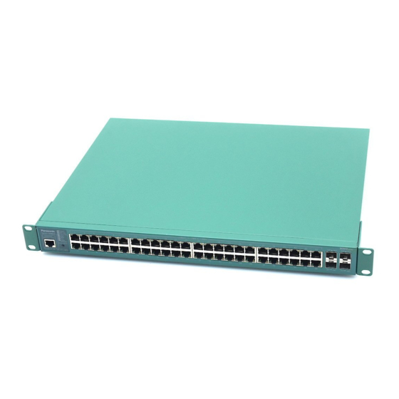
Page 14: Part Names
1.3. Part Names Back panel Front panel Magnified Fig. 1-3 Part Names... -
Page 15: Led Behavior
1.4. LED Behavior 1.4.1. LED Behavior at Start-up Upon turning this Switching Hub on, all LEDs tentatively light up. Then, the self-diagnosis of hardware is executed. Upon finishing the diagnosis, power LED and status/ECO mode LED light in solid green. Then, the Switching Hub starts working. - Page 16 Port LED display mode LED In the status mode described later, port LED shows linkup and communication status. By pressing the LED display switch button in the front panel, the display mode of port LED can be changed as follows. Port LED display mode Description STATUS/ECO...
- Page 17 No loop detection history. Right Orange Shutting down by loop detection. Light Not shutting down by loop detection. Fig. 1-4 Port LED...
-
Page 18: Loop Detection Function
1.4.3. Loop detection function Turns on the port LED with an orange light when a loop occurs in the corresponding port. At this time, the relevant port automatically shuts down (default setting: 60 sec.) to prevent loop from occurring. If the loop is still not removed, the port will shut down again. -
Page 19: Led Display Change Button
1.5. LED Display Change Button 1.5.1. Setting LED Base Mode You can select display of LEDs in this Switching Hub from two types: Status mode and Eco mode. The mode selected at system start-up is called the base mode. The base mode can be switched by keeping pressing the LED display switch button for more than 3 seconds. - Page 20 If the port LED display mode is switched to other than STATUS/ECO and then no operation is executed for more than 1 minute, the mode automatically shifts to the base mode.
-
Page 21: Installation
2. Installation Switch-M48eG can be installed to a stainless steel product, a 19-inch rack, or on the wall. 2.1. Mounting to 19-inch Rack Take out the supplied 2 mounting brackets (for 19-inch rack) and 8 screws (for fixing the main unit and the mounting bracket), and fix the brackets to the main unit by tightening screws into 4 holes located at the sides. -
Page 22: Connection
3. Connection 3.1. Connection Using a Twisted Pair Port Connection Cable Use a CAT5E or higher twisted pair cable with 8P8C RJ45 modular plug. Network Configuration 100 m or shorter 100 m 100 m or shorter or shorter Fig. -
Page 23: Connection Using An Sfp Extension Slot
3.2. Connection Using an SFP Extension Slot 1000BASE-SX: 550 m or shorter / 1000BASE-LX: 10 km or shorter 100 m 100 m or shorter or shorter Fig. 3-2 Example of Optical Fiber Cable Connection Plugging an SFP module (optional) into an SFP extension slot enables an optical fiber connection. -
Page 24: Connection To Power
3.3. Connection to Power Connect the supplied power code to the power port of this Switching Hub and connect the other end into an electric outlet. This Switching Hub operates at 100-240 V (50/60 Hz). This Switching Hub does not have a power ON/OFF switch. Plugging the power cord turns on this Switching Hub's power and the operation starts. -
Page 25: Configuration
4. Configuration Upon power on, this Switching Hub starts working as a switching hub. To use the SNMP management functionality or other unique functions, you need to configure the Switching Hub using a console port, Telnet, or SSH. In this chapter, the configuration of this Switching Hub is explained. Note: You need to configure an IP address to access this Switching Hub via Telnet or SSH. -
Page 26: Login
4.2. Login If you access the Switching Hub via the console port, a screen shown in Fig. 4-2-1 appears. If this screen does not appear, press Enter key to refresh the display or confirm that there is no error in configuration of communication mode and others. - Page 27 ============================================================================== PN28480K Remote Management System Version x.x.x.xx MAC Address: xx:x:xx:xx:xx:xx ============================================================================== Login Menu Login: Fig. 4-2-2 Login Screen (Telnet)
- Page 28 On the screens in Fig. 4-2-1 and Fig. 4-2-2, enter the login name and password. First, enter the login name. The Switching Hub's default login name is set to "manager." Enter "manager" and press the Enter key. Then, you need to enter a password, as shown in Fig. 4-2-3. The Switching Hub's default password is the same as the login name ("manager").
-
Page 29: Basic Operations On The Screen
4.3. Basic Operations on the Screen The console screen of the Switching Hub is organized as follows: 1. Title 2. Previous menu name 3. Current menu name PN28480K Local Management System Basic Switch Configuration -> System IP Configuration Menu MAC Address: xx:xx:xx:xx:xx:xx IP Address: 192.168.1.10... - Page 30 Screen Description Title The title of this screen. Shows "Local Management System" while being accessed via console. Shows "Remote Management System" while being accessed via Telnet. Previous menu Shows the name of the previous menu. Pressing "Q," name described later, opens the menu screen shown in this field.
-
Page 31: Main Menu
4.4. Main Menu After login, Main Menu appears, as shown in Fig. 4-4-1. This Switching Hub has a main menu and multiple sub-menus. These menus have a tree structure, with the main menu as its root. To move to a sub-menu, enter a command letter. - Page 32 Screen Description General Information Shows this Switching Hub's hardware, firmware information and address settings. Basic Switch Configures this Switching Hub's basic functions (such as IP address, Configuration… SNMP and port settings). Advanced Switch Configures this Switching Hub's advanced functions (such as VLAN, Configuration…...
-
Page 33: General Information Menu
4.5. General Information Menu On the Main Menu, pressing "G" opens the General Information Menu, as shown in Fig. 4-5-1. This screen shows this Switching Hub's basic information. You cannot edit shown information on this screen. PN28480K Local Management System Main Menu ->... - Page 34 PN28480K Local Management System Main Menu -> General Information System Address Information MAC Address: xx:xx:xx:xx:xx:xx IPv6 Address/PrefixLen: ::/128 IPv6 Link Local Address: IPv6 Default Gateway: Press any key to continue... Fig. 4-5-2 General Information Menu (IPv6)
- Page 35 Screen Description System up for Shows accumulated time since the Switching Hub boot-up. Boot Code Shows the version of Boot Code. Version Runtime Code Shows the version of Runtime Code. Version (Upgrading firmware version described in 4.9.1 is applicable to Runtime Code.) Hardware Shows the hardware information.
- Page 36 IPv6 Shows the Switching Hub's current IPv6 Address/PrefixLen address. ::/128 is displayed because no address is set on shipment. For configuration details, refer to 4.6.2a. IPv6 Link Local Shows the Switching Hub's current IPv6 link local Address address. :: is displayed because no address is set on shipment.
-
Page 37: Basic Switch Configuration
4.6. Basic Switch Configuration On the Main Menu, pressing "B" opens the Basic Switch Configuration Menu, as shown in Fig. 4-6-1. On this screen, you can configure the basic configuration settings, such as IP address, SMNP, and ports. PN28480K Local Management System Main Menu ->... - Page 38 Screen Description System Administration Configures the administrative information, such as Switching Configuration Hub name, location and contact information. System IP Configuration Configures the IP-address-related network information. SNMP Configuration Configures SNMP-related settings. Port Configuration Basic Configures PoE for each port. Port Configuration Configures extended port settings, such as port name.
-
Page 39: System Administration Configuration
On the Basic Switch Configuration Menu, pressing "A" opens the System Administration Configuration Menu, as shown in Fig. 4-6-2. On this screen, you can set administrative information, such as device name. PN28240K Local Management System Basic Switch Configuration -> System Admin. Configuration Menu Description: Switch-M48eG Object ID: 1.3.6.1.4.1.396.5.4.2.23 Name: Location: Contact: -------------------------------- <COMMAND>... - Page 40 Available commands are listed below. Set/edit the system name. Press "N." The command prompt changes to "Enter system name>." Enter a Switching Hub name in 50 one-byte characters or less. Set/edit the installation location information. Press "L." The command prompt changes to "Enter system location>." Enter a Switching Hub location in 50 one-byte characters or less.
-
Page 41: System Ip Configuration
4.6.2. System IP Configuration On the Basic Switch Configuration Menu, pressing "I" opens the System IP Configuration Menu, as shown in Fig. 4-6-3. On this screen, you can set IP-address-related settings for this Switching Hub. PN28480K Local Management System Basic Switch Configuration -> System IP Configuration Menu MAC Address: xx:xx:xx:xx:xx:xx IP Address:... - Page 42 Available commands are listed below. Set/edit the IP address. Press "I." The command prompt changes to "Enter IP address>." Enter an IP address for the Switching Hub. M Set/edit the subnet mask. Press "M." The command prompt changes to "Enter subnet mask>." Enter a subnet mask for the Switching Hub.
- Page 43 4.6.2.a. IPv6 Configuration On the System IP Configuration Menu, pressing "P" opens the IPv6 Configuration Menu, as shown in Fig. 4-6-4. On this screen, you can set IPv6-address-related settings for this Switching Hub. PN28480K Local Management System System IP Configuration Menu -> IPv6 Configuration Menu MAC Address: xx:xx:xx:xx:xx:xx IPv6 Status:...
- Page 44 IPv6 Default Shows the IPv6 address of the router, set as a current default gateway. Gateway :: is displayed because no address is set on shipment.
-
Page 45: Snmp Configuration
4.6.3. SNMP Configuration On the Basic Switch Configuration Menu, pressing "N" opens the SNMP Configuration Menu, as shown in Fig. 4-6-5. On this screen, you can configure the SNMP agent settings. PN28480K Local Management System Basic Switch Configuration -> SNMP Configuration Menu SNMP [M]anagement Configuration SNMP [E]xtend Configuration SNMP [T]rap Receiver Configuration... - Page 46 Available commands are listed below. Configure the SNMP manager settings. Press "M." The SNMP Management Configuration Menu opens. Configure the SNMP extend settings. Press "E." The SNMP Extend Configuration Menu opens. Configure the trap receiver settings. Press "T." The SNMP Trap Receiver Configuration Menu opens. Quit the SNMP Configuration Menu and return to the previous menu.
- Page 47 4.6.3.a. SNMP Management Configuration On the SNMP Configuration Menu, pressing "M" opens the SNMP Management Configuration Menu, as shown in Fig. 4-6-6. On this screen, you can configure the SNMP manager settings. PN28480K Local Management System SNMP Configuration -> SNMP Management Configuration Menu SNMP Manager List: Status Privilege...
- Page 48 Community Shows the current community name. Available commands are listed below. Set the SNMP manager status. Press "S." The command prompt changes to "Enter manager entry number>." Enter an SNMP manager entry number you wish to configure. Then, the command prompt changes to "Enable or Disable SNMP manger (E/D)>."...
- Page 49 4.6.3.b. IPv6 SNMP Manager On the SNMP Management Configuration Menu, pressing "P" opens the Set IPv6 SNMP Manager Menu, as shown in Fig. 4-6-7. On this screen, you can configure the SNMP IPv6 manager settings. PN28480K Local Management System SNMP Management Configuration Menu -> Set IPv6 SNMP Manager Menu SNMP Manager List: IPv6 Address ----------------------------------------------...
- Page 50 4.6.3.c. SNMP Extend Configuration On the SNMP Configuration Menu, pressing "E" opens the SNMP Extend Configuration Menu, as shown in Fig. 4-6-8. On this screen, you can configure the SNMP manager settings. PN28480K Local Management System SNMP Configuration Menu -> SNMP Extend Configuration Menu SNMP [U]ser Configuration SNMP [V]iew Configuration SNMP [G]roup Configuration...
- Page 51 4.6.3.d. SNMP User Configuration On the SNMP Extend Configuration Menu, pressing "U" opens the SNMP User Configuration Menu, as shown in Fig. 4-6-9. On this screen, you can configure the SNMP User settings. PN28480K Local Management System SNMP Extend Configuration Menu -> SNMP User Configuration Menu SNMP User List: User Name Group...
- Page 52 Available commands are listed below. Go to the screen for creating SNMP user. Press "C." The command prompt changes to " Enter User ID>." Enter an SNMP user entry number you wish to configure. Then, the SNMP User Configuration Menu opens.
- Page 53 4.6.3.e. Create SNMP User Configuration On the SNMP User Configuration Menu, pressing "C" opens the Create SNMP User Configuration Menu, as shown in Fig. 4-6-10. On this screen, you can configure the SNMP User settings. PN28480K Local Management System SNMP User Configuration Menu -> Create SNMP User Configuration Menu Index : 3 User Name Group Name...
- Page 54 IP address Shows the SNMP manager IP address. Available commands are listed below. Set a SNMP user name. Press "U." The command prompt changes to " Enter User Name>." Enter a SNMP user name. Set a name of group. Press "G." The command prompt changes to " Enter Group Name>." Enter a SNMP group name.
- Page 55 4.6.3.f. Modify SNMP User Configuration On the SNMP User Configuration Menu, pressing "O" opens the Modify SNMP User Configuration Menu, as shown in Fig. 4-6-11. On this screen, you can configure the SNMP User settings. PN28480K Local Management System SNMP User Configuration Menu -> Modify SNMP User Configuration Menu Index : 2 User Name : test...
- Page 56 IP address Shows the SNMP manager IP address. Available commands are listed below. Set a SNMP user name. Press "U." The command prompt changes to " Enter User Name>." Enter a SNMP user name. Set a name of group. Press "G." The command prompt changes to " Enter Group Name>." Enter a SNMP group name.
- Page 57 4.6.3.g. SNMP View Configuration On the SNMP Extend Configuration Menu, pressing "V" opens the SNMP View Configuration Menu, as shown in Fig. 4-6-12. On this screen, you can configure the SNMP View settings. PN28480K Local Management System SNMP Extend Configuration Menu -> SNMP View Configuration Menu Total Entry : 8 View Name Subtree...
- Page 58 Available commands are listed below. Show the next page. Press "N." The screen shows the next page. Show the previous page. Press "P." The screen shows the previous page. Go to the screen for creating SNMP view. Press "C." The command prompt changes to " Please enber view name>." Enter an SNMP view in 32 one-byte characters or less.
- Page 59 4.6.3.h. Create SNMP View Configuration On the SNMP View Configuration Menu, pressing "C" opens the Create SNMP View Configuration Menu, as shown in Fig. 4-6-13. On this screen, you can configure the SNMP View settings. PN28480K Local Management System SNMP View Configuration Menu -> Create SNMP View Configuration Menu View Name : test Subtree...
- Page 60 Available commands are listed below. Show the next page. Press "N." The screen shows the next page. Show the previous page. Press "P." The screen shows the previous page. Register an additional OID in subtree. Press "A." The command prompt changes to " Enter OID>." Enter an OID. Then, the command prompt changes to "...
- Page 61 4.6.3.i. Modify SNMP View Configuration On the SNMP View Configuration Menu, pressing "O" opens the Modify SNMP View Configuration Menu, as shown in Fig. 4-6-14. On this screen, you can configure the SNMP view settings. PN28480K Local Management System SNMP View Configuration Menu -> Modify SNMP View Configuration Menu View Name : test Subtree...
- Page 62 Available commands are listed below. Show the next page. Press "N." The screen shows the next page. Show the previous page. Press "P." The screen shows the previous page. Register an additional OID in subtree. Press "A." The command prompt changes to " Enter OID>." Enter an OID. Then, the command prompt changes to "...
- Page 63 4.6.3.j. SNMP Group Configuration On the SNMP Extend Configuration Menu, pressing "G" opens the SNMP Group Configuration Menu, as shown in Fig. 4-6-15. On this screen, you can configure the SNMP Group settings. PN28480K Local Management System SNMP Extend Configuration Menu -> SNMP Group Configuration Menu Total Entry : 5 Group Name Ver.
- Page 64 Available commands are listed below. Show the next page. Press "N." The screen shows the next page. Show the previous page. Press "P." The screen shows the previous page. Go to the screen for creating SNMP group. Press "C." The command prompt changes to " Please input the SNMP Group Name>." Enter an SNMP view in 32 one-byte characters or less.
- Page 65 4.6.3.k. Create SNMP Group Configuration On the SNMP Group Configuration Menu, pressing "C", input "SNMP Group name","SNMP Version", opens the Create SNMP Group Configuration Menu, as shown in Fig. 4-6-16. On this screen, you can configure the SNMP Group settings. PN28480K Local Management System SNMP Group Configuration Menu ->...
- Page 66 Available commands are listed below. Set a SNMP version. Press "S." The command prompt changes to " Enter SNMP version>." Press "1" for SNMP v1. Press "2" for SNMP v2c. Press "3" for SNMP v3. Set a name of view to notify. Press "O."...
- Page 67 4.6.3.l. Modify SNMP Group Configuration On the SNMP Group Configuration Menu, pressing "O", input "SNMP Group name","SNMP Version", opens the Modify SNMP Group Configuration Menu, as shown in Fig. 4-6-17. On this screen, you can configure the SNMP Group settings. PN28480K Local Management System SNMP Group Configuration Menu ->...
- Page 68 Available commands are listed below. Set a SNMP version. Press "S." The command prompt changes to " Enter SNMP version>." Press "1" for SNMP v1. Press "2" for SNMP v2c. Press "3" for SNMP v3. Set a name of view to notify. Press "O."...
- Page 69 4.6.3.m. SNMP Trap Receiver Configuration On the SNMP Configuration Menu, pressing "T" opens the SNMP Trap Receiver Configuration Menu, as shown in Fig. 4-6-18. On this screen, you can configure the SNMP trap receiver settings. PN28480K Local Management System SNMP Configuration -> SNMP Trap Receiver Configuration Menu Trap Receiver List: Status Type...
- Page 70 Community Shows the current community name of a trap receiver. Available commands are listed below. Enable/disable the trap receiver. Press "S." The command prompt changes to "Enter manager entry number>." Enter an entry number for the trap receiver you wish to configure. Then, the command prompt changes to "Enable or Disable Trap Receiver (E/D)>."...
- Page 71 4.6.3.n. Enable/Disable Individual Trap On the SNMP Trap Receiver Configuration Menu, pressing "d" opens the Enable/Disable Individual Trap Menu, as shown in Fig. 4-6-19. On this screen, you can configure the trap sending settings. PN28480K Local Management System SNMP Trap Receiver Configuration -> Enable/Disable Individual Trap Menu Coldstart : Disabled SNMP Authentication Failure :...
- Page 72 Available commands are listed below. Enable/disable the trap sending at a coldstart. Press "C." The command prompt changes to " Enable or Disable coldstart trap (E/D)>." Press "E" to enable the trap sending. Press "D" to disable it. Enable/disable the trap sending at an SNMP authentication failure. Press "A."...
- Page 73 4.6.3.o Set IPv6 Trap Receiver On the SNMP Trap Receiver Configuration Menu, pressing "P" opens the Set IPv6 Trap Receiver Menu, as shown in Fig. 4-6-20. On this screen, you can set SNMP trap receiver. PN28480K Local Management System SNMP Trap Receiver Configuration Menu -> Set IPv6 Trap Receiver Menu Trap Receiver List: IPv6 Address ----------------------------------------------...
-
Page 74: Port Configuration Basic
4.6.4. Port Configuration Basic On the Basic Switch Configuration Menu, pressing "p" opens the Port Configuration Menu, as shown in Fig. 4-6-21. On this screen, you can configure port status display settings and port settings. PN28480K Local Management System Basic Switch Configuration -> Port Configuration Basic Menu Port Trunk Type Admin... - Page 75 Screen Description Port Shows the port number. Trunk Shows the group number for a trunked port. Type Shows the port type. 100TX The port type is 10/100BASE-TX. 1000T The port type is 10/100/1000BASE-T. 1000X The port type is SFP port. Admin Shows the current port status.
- Page 76 Available commands are listed below. Show the next page. Press "N." The screen shows the next port. Show the previous page. Press "P." The screen shows the previous port. Enable/disable a port. Press "A." The command prompt changes to "Select port number to be changed>." Enter a port number you wish to change.
- Page 77 Press "S." The command prompt changes to "Enter port number>." Enter a port number (from 1 to 48) you wish to change. Press "0" to change the settings of all ports at a time. Then, the command prompt changes to "Enable or Disable Auto-MDl for port # (E/D)>."...
-
Page 78: Port Configuration Extend
4.6.5. Port Configuration Extend On the Basic Switch Configuration Menu, pressing "e" opens the Port Configuration Menu, as shown in Fig. 4-6-22. On this screen, you can configure port status display settings and port settings. PN28480K Local Management System Basic Switch Configuration -> Port Configuration Extend Menu Jumbo Status : Disabled Port Trunk Type... - Page 79 Screen Description Jumbo Shows the current jumbo frame settings. The factory default setting is "Disabled." Enabled Jumbo frame is enabled. Disabled Jumbo frame is disabled. Port Shows the port number. Trunk Shows the group number for a trunked port. Type Shows the port type.
- Page 80 Available commands are listed below. Show the next page. Press "N." The screen shows the next port. Show the previous page. Press "P." The screen shows the previous port. An EAP Packet forwarding can be assigned to each port. Press "E." The command prompt changes to "Select port number to be changed>." Enter a port number you wish to change.
-
Page 81: Port Configuration Power Saving
4.6.6. Port Configuration Power Saving The MNO series power saving mode is our unique function for automatically detecting the port connection status and minimizing power consumption if not connected. This Switching Hub supports two modes: the Half mode for giving priority to connectivity with another device, and the Full mode for minimizing power consumption. - Page 82 Screen Description Port Shows the port number. Link Shows the current link status. Link is established successfully. Down Link is not established. Trunk Shows the group number for a trunked port. Type Shows the port type. 100TX The port type is 10/100BASE-TX. 1000T The port type is 10/100/1000BASE-T.
- Page 83 Available commands are listed below. Show the next page. Press "N." The screen shows the next port. Show the previous page. Press "P." The screen shows the previous port. Set the MNO series power saving mode. Press "S." The command prompt changes to "Select port number to be changed>." Enter a port number you wish to change.
-
Page 84: System Security Configuration
4.6.7. System Security Configuration On the Basic Switch Configuration Menu, pressing "S" opens the System Security Configuration screen, as shown in Fig. 4-6-24. On this screen, you can configure the access control settings to this Switching Hub for configuration and management. PN28480K Local Management System Basic Switch Configuration ->... - Page 85 Access is disabled. IP Setup Shows the access settings for the IP address configuration software, Interface: bundled with the Panasonic network cameras. The factory default setting is "Enabled." * For instructions, refer to Appendix C. Enabled: Access is enabled. Disabled: Access is disabled.
- Page 86 Press "A." The Telnet Access Limitation Menu opens. For configuration details, refer to the next section (4.6.7.a). Configures the access settings for the IP address configuration software, bundled with the Panasonic network cameras. Press "I." The command prompt changes to "Enable or Disable IP setup interface (E/D)>."...
- Page 87 Press "O." The command prompt changes to "Enter manager entry number>." Press "1" to change the first login method. Press "2" to change the second login method. Then, the command prompt changes to the "Select the login method." Press "L" to use the user name and password set in the Switching Hub.
- Page 88 4.6.7.a. Telnet Access Limitation Configuration On the System Security Configuration Menu, pressing "A" opens the Telnet Access Limitation screen, as shown in Fig. 4-6-25. In this screen, you can configure limitation of equipment accessing to this Switching Hub via Telnet. PN28480K Local Management System System Security Configuration ->...
- Page 89 Available commands are listed below. Enable/Disable the access limitation from Telnet. Set the access limitation from Telnet to Enable. Set the access limitation from Telnet to Disable. Set an IP address to be permitted. Five ranges can be set up. Press "A."...
- Page 90 4.6.7.b. IPv6 Telnet Access Limitation On the Telnet Access Limitation Menu, pressing "S" opens the IPv6 Telnet Access Limitation Menu, as shown in Fig. 4-6-26. On this screen, you can configure limitation of equipment accessing to this Switching Hub via Telnet.
- Page 91 Available commands are listed below. Enable/Disable the access limitation from IPv6 Telnet. Set the access limitation from IPv6 Telnet to Enable. Set the access limitation from IPv6 Telnet to Disable. Set an IPv6 address to be permitted. Five ranges can be set up. Press "A."...
- Page 92 4.6.7.c. RADIUS Configuration On the System Security Configuration Menu, pressing "R" opens the RADIUS Configuration screen, as shown in Fig. 4-6-27. On this screen, you can configure access setting to RADIUS server that is used in login authentication. PN28480K Local Management System System Security Configuration ->...
- Page 93 Available commands are listed below. Set a NAS ID (NAS Identifier). Press "I." The command prompt changes to "Enter NAS ID>." Enter NAS ID within 16 one-byte characters. Set an IP address of RADIUS server. Press "I." The command prompt changes to " Enter RADIUS server index>." Enter a RADIUS server entry number between 1 and 5.
- Page 94 4.6.7.d. Set IPv6 RADIUS Server On the RADIUS Configuration Menu, pressing "P" opens the Set IPv6 RADIUS Server Menu, as shown in Fig. 4-6-28. On this screen, you can configure access setting to RADIUS server that is used in login authentication.
- Page 95 4.6.7.e. Syslog Transmission Configuration On the System Security Configuration Menu, pressing "G" opens the Syslog Transmission Configuration screen, as shown in Fig. 4-6-29. On this screen, you can configure the setting of the Syslog server to which a system log Is sent.
- Page 96 Available commands are listed below. Configure the status of Syslog transmission. Press "S." The command prompt changes to " Enter manager entry number>." Enter a Syslog server entry number between 1 and 2. The command prompt changes to " Enable or Disable Server (E/D)>." Press "E"...
- Page 97 4.6.7.f. Set IPv6 Syslog Server On the System Transmission Configuration Menu, pressing "P" opens the Set IPv6 Syslog Server screen, as shown in Fig. 4-6-30. On this screen, you can configure the setting of the Syslog server to which a system log Is sent. PN28480K Local Management System System Security Configuration ->...
- Page 98 4.6.7.g. SSH Server Configuration On the System Security Configuration, pressing "H" opens the SSH Server Configuration screen, as shown in Fig. 4-6-31. On this screen, you can configure the SSH server setting. This Switching Hub supports SSHv2 only. Use and connect a client supporting SSHV2. PN28480K Local Management System System Security Configuration ->...
- Page 99 Available commands are listed below. Generate an SSH server key. Press "G" to generate an SSH server key. Configure the SSH access setting. Press "H." The command prompt changes to "Enable or Disable SSH server (E/D)>." Press "E" to enable the access. Press "D" to disable the access. Configure the idle timeout settings for automatically terminating an SSH-connected session if no input is made.
- Page 100 4.6.7.h. LED Base Mode Configuration On the System Security Configuration, pressing "B" opens the LED Base Mode Configuration screen, as shown in Fig. 4-6-32. On this screen, you can configure the LED base mode setting. PN28480K Local Management System System Security Configuration -> LED Base Mode Configuration System LED base-mode: Status Note: Save Configuration to Flash will be executed when LED Base Mode changed.
- Page 101 4.6.8.i. Fan Control Configuration On the System Security Configuration, pressing "F" opens the Fan Control Configuration screen, as shown in Fig. 4-6-33. On this screen, you can configure the Fan Control setting. PN28480K Local Management System System Security Configuration -> Fan Control Configuration Fan Speed : High -------------------------------- <COMMAND>...
-
Page 102: Forwarding Database
4.6.8. Forwarding Database On the Basic Switch Configuration Menu, pressing "F" opens the Forwarding Database Information Menu, as shown in Fig. 4-6-34. In this screen, a list of MAC address required for transferring packets that have been learned and recorded. Also, you can add or delete MAC address statically. - Page 103 4.6.8.a. Adding or Deleting MAC Address On the Forwarding Database Information Menu, pressing "S" opens the Static Address Table Menu, as shown in Fig. 4-6-35. In this screen, you can add or delete a MAC address statically. PN28480K Local Management System Forwarding Database Menu ->...
- Page 104 4.6.8.b. Setting MAC Address Auto-learning On the Forwarding Database Information Menu, pressing "A" opens the MAC Learning Menu, as shown in Fig. 4-6-36. On this screen, you can configure the MAC address auto-learning setting for each port and limit the number of MAC address auto-learning.
- Page 105 Note: If MAC address auto-learning is disabled, communication cannot be established unless MAC address is registered statistically. Note: Assuming that the number of learned MAC addresses reaches the limit, and if a frame with new source MAC address that has not been learned is received, this frame is discarded.
- Page 106 4.6.8.c. Displaying All MAC Addresses On the Forwarding Database Information Menu, pressing "M" opens the Display MAC Address by MAC screen, as shown in Fig. 4-6-37. In this screen, you can display all MAC address tables in this Switching Hub. PN28480K Local Management System Forwarding Database Menu ->...
-
Page 107: Time Configuration
4.6.9. Time Configuration In this Switching Hub, it is possible to set the exact time by synchronizing the internal clock to an external SNTP server's clock with a support of SNTP (Simple Network Time Protocol). On the Basic Switch Configuration Menu, pressing "T" opens the Time Configuration Menu, as shown in Fig. - Page 108 PN28480K Local Management System Basic Switch Configuration -> Time Configuration Menu Time ( HH:MM:SS ) : 10:20:33 Date ( YYYY/MM/DD ) : 2009/04/01 Wednesday SNTP Server IP : 192.168.0.2 SNTP Server IPv6 : :: SNTP Polling Interval : 1440 Min Time Zone : (GMT+09:00) Osaka,Sapporo,Tokyo Daylight Saving : N/A...
- Page 109 Available commands are listed below. Set the time of internal clock of this Switching Hub. Press "C." The command prompt changes to "Enter Date(Year) >" and enter a year. Then, the command prompt changes to "Enter Date(Month) >" and enter a month. Then, the command prompt changes to "Enter Date(Day) >"...
-
Page 110: Arp Table
4.6.10. ARP Table On the Basic Switch Configuration Menu, pressing "R" opens the ARP Table screen, as shown in Fig. 4-6-40. In this screen, you can refer and configure ARP table. PN28480K Local Management System Basic Switch Configuration -> ARP Table Sorting Method : By IP ARP Age Timeout : 7200 seconds... - Page 111 Available commands are listed below. Show the next page. Press "N." The screen shows the next page. Show the previous page. Press "P." The screen shows the previous page. Set the age-out time of ARP table. Press "T." The command prompt changes to "Enter ARP age timeout value >." Enter the age-out time of ARP table with a value of 30 to 86400 (seconds).
-
Page 112: Ndp Table
4.6.11. NDP Table On the Basic Switch Configuration Menu, pressing "D" opens the NDP Table screen, as shown in Fig. 4-6-41. In this screen, you can refer and configure NDP table. PN28480K Local Management System Basic Switch Configuration -> NDP Table Sorting Method: By IP NDP Reachable Time: 30 Seconds... - Page 113 Available commands are listed below. Show the next page. Press "N." The screen shows the next page. Show the previous page. Press "P." The screen shows the previous page. Set the IPv6 Reachable time of NDP table. Press "R." The command prompt changes to " Enter NDP reachable time value>." Enter the IPv6 Reachable time of NDP table with a value of 30 to 86400 (seconds).
-
Page 114: Advanced Switch Configuration
4.7. Advanced Switch Configuration On the Main Menu, pressing "A" opens the Advanced Switch Configuration Menu, as shown in Fig. 4-7-1. On this screen, you can configure settings of VLAN, link aggregation, port monitoring, access control, storm control, QoS, storm control, 802.1X Port Based Access Control, loop detection/shut-off, port grouping, digital diagnostic monitoring, and static multicast address functions. - Page 115 Static Multicast Address Configures Static Multicast Address setting. Configuration Quit to previous menu Quits the Advanced Switch Configuration Menu and returns to the Main menu.
-
Page 116: Vlan Management
4.7.1. VLAN Management 4.7.1.a. Features Corresponding to IEEE802.1Q compatible Tag VLAN, a frame can be sent with a VLAN tag (hereinafter referred to as just "tag"). Having two different parameters of VLAN ID and PVID, forwarding destination of an untagged frame is determined by a combination of these parameters. - Page 117 4.7.1.b. VLAN Management Menu On the Advanced Switch Configuration Menu, pressing "V" opens the VLAN Management Menu, as shown in Fig. 4-7-2. On this screen, you can configure VLAN-related settings. PN28480K Local Management System Advanced Switch Configuration -> VLAN Management Menu Total VLANs : 1 Internet Mansion : Disabled Uplink...
- Page 118 A management VLAN that is allowed to communicate with CPU. DOWN Not a management VLAN. Available commands are listed below. Show the next page. Press "N." The screen shows the next page. Show the previous page. Press "P." The screen shows the previous page. Go to the screen for creating VLAN.
- Page 119 Return to the previous menu. Note: VLAN 1 is set on shipment, and all ports belong to this VLAN. Also, the management VLAN is enabled. Note: When creating a new VLAN, PVID (after-mentioned) is not changed in conjunction with this new creation. After registering VLAN on this screen, make sure to confirm the configuration operation and content on the configuration screen in Fig.
- Page 120 4.7.1.c. VLAN Creation Menu On the VLAN Management Menu, pressing "C" opens the VLAN Creation Menu , as shown in Fig. 4-7-3. On this screen, you can create VLAN. PN28480K Local Management System VLAN Management -> VLAN Creation Menu VLAN ID VLAN Name Port Members -------------------------------- <COMMAND>...
- Page 121 Available commands are listed below. Set a VLAN ID (VLAN Identifier). Press "S." The command prompt changes to "Enter VLAN ID>." Enter a VLAN ID. Set a name of VLAN. Press "N." The command prompt changes to "Enter VLAN name>." Enter a VLAN name within 30 one-byte characters.
- Page 122 4.7.1.d. VLAN Modification Menu On the VLAN Management Menu, pressing "o" and specifying target VLAN ID open the VLAN Modification Menu, as shown in Fig. 4-7-4. On this screen, you can modify VLAN-related setting information. PN28480K Local Management System VLAN Management -> VLAN Modification Menu VLAN ID VLAN Name Port Members...
- Page 123 Available commands are listed below. Set a name of VLAN. Press "N." The command prompt changes to "Enter VLAN name>." Enter a VLAN name within 30 one-byte characters. Set a member of VLAN. Press "P." The command prompt changes to "Enter egress port number>." Enter a port number you wish to set.
- Page 124 4.7.1.e. VLAN Port Configuration Menu On the VLAN Management Menu, pressing "S" opens the VLAN Port Configuration Menu, as shown in Fig. 4-7-5. In this screen, you can configure VLAN-related settings by port. PN28480K Local Management System VLAN Management -> VLAN Port Configuration Menu Port PVID Acceptable Frame Type ---- ---- --------------------- Admit All...
- Page 125 Available commands are listed below. Show the next page. Press "N." The screen shows the next page. Show the previous page. Press "P." The screen shows the previous page. Configure PVID settings. Press "V." The command prompt changes to "Enter port number>." Enter a port number you wish to configure.
-
Page 126: Link Aggregation
4.7.2. Link Aggregation 4.7.2.a. About Link aggregation Link aggregation is a function that is possible to increase redundancy of network paths and bandwidth between Switching Hubs by grouping multiple ports to a trunk for connection. In this Switching Hub, up to 8 ports can be assigned to 1 group, and 8 groups can be created. - Page 127 4.7.2.b. Link Aggregation Menu On the Advanced Switch Configuration Menu, pressing "L" opens the Trunk Configuration Menu, as shown in Fig. 4-7-6. On this screen, you can configure Link Aggregation settings. PN28480K Local Management System Advanced Switch Configuration -> Link Aggregation Menu Group Status Port Members...
-
Page 128: Port Monitoring Configuration Menu
4.7.3. Port Monitoring Configuration Menu On the Advanced Switch Configuration Menu, pressing "M" opens the Port Monitoring Configuration Menu, as shown in Fig. 4-7-7. To analyze communications, such as by protocol analyzer, in this Switching Hub, you can monitor packets between other ports that are normally filtered and cannot be monitored. - Page 129 Screen Description Monitoring Port Shows the destination port number of data to be monitored. Be Monitored Shows the target port number to be monitored. Port(s) Direction Shows the communication direction of target packet to be monitored. Monitors a transmit packet. Monitors a receive packet.
-
Page 130: Access Control Configuration Menu
4.7.4. Access Control Configuration Menu On the Advanced Switch Configuration Menu, pressing "A" opens the Access Control Configuration Menu, as shown in Fig. 4-7-8. On this screen, you can set Access Control. PN28480K Local Management System Advanced Switch Configuration -> Access Control Configuration Menu [C]lassifier [I]n-Profile Action [O]ut-Profile Action... - Page 131 4.7.4.a. Classifier Configuration Menu On the Access Control Configuration Menu, pressing "C" opens the Classifier Configuration Menu, as shown in Fig. 4-7-9. On this screen, you can set classifier. PN28480K Local Management System Access Control Configuration -> Classifier Configuration Menu Multifield Classifier: Total Entries : 1 Index Src IP Addr/Mask...
- Page 132 Available commands are listed below. Show the next page. Press "N." The screen shows the next page. Show the previous page. Press "P." The screen shows the previous page. Create a classifier. Press "C." The Create Classifier Configuration Menu opens. For the Create Classifier Configuration Menu, refer to the next section (4.7.4.b).
- Page 133 4.7.4.b. Create Classifier Configuration Menu On the Classifier Configuration Menu, pressing "C" opens the Create Classifier Configuration Menu, as shown in Fig. 4-7-10. On this screen, you can create a classifier. PN28480K Local Management System Classifier Configuration -> Create Classifier Configuration Menu Classifier Index VLAN ID : 802.1p Priority :...
- Page 134 Screen Description Classifier Index Shows the classifier index. VLAN ID Shows the VLAN ID. 802.1p Priority Shows the priority of IEEE802.1p. DSCP Shows the DSCP value. IPv6 DSCP Shows the IPv6 DSCP value Protocol Shows the protocol type. TCP SYN Flag Shows whether a TCP SYN flag is set for filtering.
- Page 135 Available commands are listed below. Set a classifier index. Press "C." The command prompt changes to "Enter Classifier Index>." Enter a classifier index with a value of 1 to 65535. Set the source MAC address to be filtered. Press "S." The command prompt changes to "Enter source MAC address>." Enter the source MAC address as xx:xx:xx:xx:xx:xx.
- Page 136 Press "M." The command prompt changes to "Enter ICMP type>." Enter an ICMP type with a value of 0 to 18. Set a TCP SYN flag to be filtered. (* Protocol needs to be set to TCP.) Press "Y." The command prompt changes to "Set TCP SYN flag (Y/N)>." Press "Y" for filter with a TCP SYN flag.
- Page 137 4.7.4.c. Classifier Configuration Menu On the Classifier Configuration Menu, pressing "M" opens the More Classifier Information screen, as shown in Fig. 4-7-11 and Fig. 4-7-12. On this screen, you can refer to classifier information. PN28480K Local Management System Access Control Configuration -> Classifier Configuration Menu Multifield Classifier: Total Entries : 1 Index Source MAC Addr./ Mask...
- Page 138 PN28480K Local Management System Access Control Configuration -> Classifier Configuration Menu Multifield Classifier: Total Entries : 1 Index 802.1p VLAN ID TCP(SYN) ICMPTP ----- ------ ------- -------- ------------------------------------------------- 1 Ignore Ignore Ignore Ignore Press any key to continue... Fig. 4-7-12 Classifier Configuration Menu 2 Screen Description Total Entries Shows the number of classifiers (number of indexes) created.
- Page 139 4.7.4.d. Show Detailed Entries Information Menu On the Classifier Configuration Menu, pressing "S" opens the Show Detailed Entries Information Menu, as shown in Fig. 4-7-13. On this screen, you can refer to detailed classifier information. Classifier needs to be created before reference.
- Page 140 Screen Description Classifier Index Shows the classifier index. Source MAC Address Shows the source MAC address. Source Mask length Shows the length (bits) of source address mask. Destination MAC Address Shows the destination MAC address. Destination Mask length Shows the length (bits) of destination address mask. VLAN ID Shows the VLAN ID.
- Page 141 4.7.4.e. In-Profile Action Configuration Menu On the Access Control Configuration Menu, pressing "I" opens the In-Profile Action Configuration Menu, as shown in Fig. 4-7-14. On this screen, you can configure in-profile setting. PN28480K Local Management System Access Control Configuration -> In-Profile Action Configuration Menu In-Profile Action: Total Entries : 0 Index Deny/Permit Policed-DSCP...
- Page 142 Available commands are listed below. Show the next page. Press "N." The screen shows the next page. Show the previous page. Press "P." The screen shows the previous page. Create in-profile. Press "C." The Create In-Profile Action Menu opens. Refer to the next section (4.7.4.f).
- Page 143 4.7.4.f. Create In-profile Action Menu On the In-Profile Action Configuration screen, pressing "C" opens the Create In-Profile Action Menu, as shown in Fig. 4-7-15. On this screen, you can create in-profile action. PN28480K Local Management System In-Profile Action Configuration -> Create In-Profile Action Menu Index Deny/Permit : Permit...
- Page 144 Available commands are listed below. Set an in-profile index number. Press "I." The command prompt changes to "Enter in-profile action index>." Enter an index number with a value of 1 to 65535. Deny/permit packets. Press "D." The command prompt changes to "Select Deny/Permit (1-2)>." Press "1"...
- Page 145 4.7.4.g. Out-Profile Action Configuration Menu On the Access Control Configuration Menu, pressing "O" opens the Out-Profile Action Configuration Menu, as shown in Fig. 4-7-16. On this screen, you can configure out-profile setting. PN28480K Local Management System Access Control Configuration -> Out-Profile Action Configuration Menu Out-Profile Action: Total Entries :0 Index...
- Page 146 Available commands are listed below. Show the next page. Press "N." The screen shows the next page. Show the previous page. Press "P." The screen shows the previous page. Create out-profile. Press "C." The Create Out-Profile Action Menu opens. Refer to the next section (4.7.4.h).
- Page 147 4.7.4.h. Create Out-profile Action Menu On the Out-Profile Action Configuration screen, pressing "C" opens the Create Out-Profile Action Menu, as shown in Fig. 4-7-17. On this screen, you can create out-profile action. PN28480K Local Management System Out-Profile Action Configuration -> Create Out-Profile Action Menu Index Deny/Permit : Deny...
- Page 148 Available commands are listed below. Set an out-profile index number. Press "I." The command prompt changes to "Enter Out-Profile action index>." Enter an index number with a value of 1 to 65535. Set the committed rate. Press "C." The command prompt changes to "Enter committed rate>." Enter the committed rate with a value of 1 to 1000.
- Page 149 4.7.4.i. Port List Configuration Menu On the Access Control Configuration Menu, pressing "L" opens the Port List Configuration Menu, as shown in Fig. 4-7-18. On this screen, you can set a port list to apply Access Control. When using both Access Control and Link Aggregation functions, assign a practical physical port number, not a logical port created in Link Aggregation.
- Page 150 Available commands are listed below. Show the next page. Press "N." The screen shows the next page. Show the previous page. Press "P." The screen shows the previous page. Create a port list. Press "C." The command prompt changes to "Enter port list index>." Enter an index number to be created.
- Page 151 4.7.4.j. Policy Configuration Menu On the Access Control Configuration Menu, pressing "P" opens the Policy Configuration Menu, as shown in Fig. 4-7-19. On this screen, you can configure the policy settings. PN28480K Local Management System Access Control Configuration -> Policy Configuration Menu Policy : Total Entries : 0 Index Classifier Seq.
- Page 152 Available commands are listed below. Show the next page. Press "N." The screen shows the next page. Show the previous page. Press "P." The screen shows the previous page. Create a policy. Press "C." The Create Policy Configuration Menu opens. For the Create Policy Configuration Menu, refer to the next section (4.7.4.k).
- Page 153 4.7.4.k. Create Policy Configuration Menu On the Policy Configuration Menu, pressing "C" opens the Create Policy Configuration Menu, as shown in Fig. 4-7-20. On this screen, you can create a policy. PN28480K Local Management System Policy Configuration -> Create Policy Configuration Menu Policy Index Classifier Index Policy Sequence...
- Page 154 Available commands are listed below. Set a policy index number. Press "P." The command prompt changes to "Enter policy index>." Enter a policy index number. Set an index number of applicable classifier. Press "C." The command prompt changes to "Enter classifier index>." Enter an index number of applicable classifier.
-
Page 155: Quality Of Service Configuration
4.7.5 Quality of Service Configuration On the Advanced Switch Configuration Menu, pressing "S" opens the Quality of Service Configuration Menu, as shown in Fig. 4-7-21. You can configure the QoS (Quality of Service) setting of the Switching Hub. PN28480K Local Management System Main Menu ->... - Page 156 4.7.5.a. Traffic Class Configuration Menu On the Quality of Service Configuration Menu, pressing "T" opens the Traffic Class Configuration screen, as shown in Fig. 4-7-22. On this screen, you can configure the traffic class setting. PN28480K Local Management System Quality of Service Configuration -> Traffic Class Configuration Menu QoS Status: Disabled Priority Traffic Class...
- Page 157 4.7.5.b. Egress Rate Limiting Configuration Menu On the Quality of Service Configuration Menu, pressing "C" opens the Egress Rate Limiting Configuration Menu, as shown in Fig. 4-7-23. On this screen, you can set bandwidth control. PN28480K Local Management System Quality of Service Configuration -> Egress Rate Limiting Configuration Menu Port Bandwidth Status...
- Page 158 Press "S." The command prompt changes to "Enter port number e.g.: 1, 3, 5-48>." Enter a port number to designate. Then, the command prompt changes to "Enable or Disable Status (E/D)>." Press "E" to enable the bandwidth control. Press "D" to disable it. Return to the previous menu.
-
Page 159: Storm Control Configuration Menu
4.7.6. Storm Control Configuration Menu On the Advanced Switch Configuration Menu, pressing "o" opens the Storm Control Configuration Menu, as shown in Fig. 4-7-24. You can set the storm control for unknown unicast, broadcast, and multicast traffic. PN28480K Local Management System Advanced Switch Configuration ->... - Page 160 Available commands are listed below. Enable/disable the storm control for unknown unicast traffic. Press "D." The command prompt changes to "Enter port number>." Enter a port number to designate. Then, the command prompt changes to "Enable or Disable DLF storm control status>." Press "E" to enable the unknown unicast control. Press "D"...
-
Page 161: Port Based Access Control
4.7.7 802.1X Port Based Access Control On the Advanced Switch Configuration Menu, pressing "X" opens the 802.1X Port Based Access Control Configuration Menu, as shown in Fig. 4-7-25. You can set the 802.1X Port Based Access control. The supported authentication method is EAP-MD5, TLS, and PEAP. PN28480K Local Management System Advanced Switch Configuration ->... - Page 162 Supplicant Shows the timeout for the client. The factory default setting is 30 Timeout seconds. Server Timeout Shows the timeout for the authentication server. The factory default setting is 30 seconds. Maximum The maximum number of times of retransmitting an authentication Request request.
- Page 163 Available commands are listed below. Set the port number. Press "P." The command prompt changes to "Enter port number>." Enter the port number you wish to configure. Set the operation mode for authentication requests. Press "C." The command prompt changes to "Select authenticator port control (A/U/F) >."...
-
Page 164: Loop Detection Configuration Menu
4.7.8 Loop Detection Configuration Menu On the Advanced Switch Configuration Menu, pressing "D" opens the Loop Detection Configuration Menu, as shown in Fig. 4-7-26. On this screen, you can set the loop detection and shut-off function. For network configuration, also refer to "Appendix C. Example of Network Configuration using Loop Detection/Shut-off Function and Its Precautions"... - Page 165 Screen Description Global Loop Shows the status of loop detection/shut-off function. Detection Status Enabled The loop detection/shut-off function is enabled. (Factory default setting) Disabled The loop detection/shut-off function is disabled. Port Shows the port number. Trunk Shows the link aggregation group ID. Link Shows the state of linkup.
- Page 166 Available commands are listed below. Set the status of loop detection/shut-off function. Press "E." The command prompt changes to "Enable or Disable Loop Detection (E/D)>." Press "E" to enable the loop detection/shut-off function. Press "D" to disable it. Press "I." The Loop History Information screen opens. Set the status of loop detection/shut-off function of each port.
- Page 167 4.7.7.a. Loop History Information On the Loop Detection Configuration Menu, pressing "I" opens the Loop History Information screen, as shown in Fig. 4-7-27. On this screen, the date and time of detecting loop and the event information are listed. PN28480K Local Management System Loop Detection Configuration Menu ->...
-
Page 168: Port Group Configuration Menu
4.7.9. Port Group Configuration Menu On the Advanced Switch Configuration Menu, pressing "P" opens the Port Group Configuration Menu, as shown in Fig. 4-7-29. On this screen, you can configure port grouping. If a port grouping is configured, ports designated as members of the port group can communicate only among member ports in the same group. - Page 169 PN28480K Local Management System Advanced Switch Configuration -> Port Group Configuration Menu Total Groups : 0 Group ID Group Name Group Member Status -------- ---------------- ------------------------------------------- -------- -------------------------------- <COMMAND> ----------------------------------- [N]ext Page [C]reate Group [D]elete Group [P]revious Page [M]odify Group [E]nable or Disable Group [Q]uit to previous menu Command>...
- Page 170 Available commands are listed below. Show the next page. Press "N." The screen shows the next page. Show the previous page. Press "P." The screen shows the previous page. Go to the screen for creating a port group. Press "C." The Port Group Create Menu opens. For details, refer to the next section (4.7.9.a).
- Page 171 4.7.8.a. Port Group Creation Menu On the Port Group Management Menu, pressing "C" opens the Port Group Creation Menu, as shown in Fig. 4-7-30. On this screen, you can create a port group. PN28480K Local Management System Port Group Configuration -> Port Group Configuration Menu Group ID Group Name Port Members...
- Page 172 Available commands are listed below. Set a port group ID. Press "G." The command prompt changes to "Enter Port Group ID>." Enter a port group ID. Set a port group name. Press "N." The command prompt changes to "Enter Port Group name>." Enter a port group name in 16 one-byte characters or less.
- Page 173 4.7.8.b. Port Group Modification Menu On the Port Group Management Menu, pressing "o" and then specifying a port group ID open the Port Group Modification Menu, as shown in Fig. 4-7-31. On this screen, you can modify the port group setting. PN28480K Local Management System Port Group Configuration ->...
- Page 174 Available commands are listed below. Set a port group name. Press "N." The command prompt changes to "Enter Port Group name>." Enter a port group name in 16 one-byte characters or less. Set a port group member. Press "P." The command prompt changes to "Enter egress port number>." Enter a port number you wish to set.
-
Page 175: Digital Diagnostic Monitoring Menu
4.7.10. Digital Diagnostic Monitoring Menu On the Advanced Switch Configuration Menu, pressing "G" opens the Digital Diagnostic Monitoring Menu, as shown in Fig. 4-7-32. On this screen, you can show the SFP status and set the alarm. PN28480K Local Management System Advanced Switch Configuration ->... - Page 176 High Alarm Shows the high alarm value. High Warning Shows the high warning value. Low Alarm Shows the low alarm value. Low Warning Shows the low warning value.
- Page 177 Available commands are listed below. Show the next page. Press "N." The screen shows the next port. Show the previous page. Press "P." The screen shows the previous port. Enable/disable a sending SNMP trap. Press "S." The command prompt changes to " Enable or Disable Limit trap(E/D)>." Press "E"...
-
Page 178: Static Multicast Address
4.7.11. Static Multicast Address On the Advanced Switch Configuration Menu, pressing "U" opens the Static Multicast Address Table Menu, as shown in Fig. 4-7-33. On this screen, you can set the forwarding multicast group to the specific port only. PN28480K Local Management System Advanced Switch Configuration ->... - Page 179 Available commands are listed below. Show the next page. Press "N." The screen shows the next page. Show the previous page. Press "P." The screen shows the previous page. Register an additional Multicast group address. Press "A." The command prompt changes to " Enter VLAN ID >." Enter a VLAN ID between 1 and 4094.
-
Page 180: Statistics
4.8. Statistics On the Main Menu, pressing "S" opens the Statistics Menu, as shown in Fig. 4-8-1. On this screen, you can confirm the statistics information of packets and thereby grasp the network status. PN28480K Local Management System Main Menu -> Statistics Menu Port: 1 Refresh: 300 Sec. - Page 181 Available commands are listed below. Show the values of the next port. Press "N." The screen shows the counter values of the next port. Disabled in Port Show the values of the previous port. Press "P." The screen shows the counter values of the previous port. Disabled in Port 1.
- Page 182 On this screen, you can display two types of values: Values accumulated since booting the Switching Hub (Fig. 4-8-1) and values accumulated since the counter reset (Fig. 4-8-2). An accumulated value since booting is retained even if the counter is reset. PN28480K Local Management System Main Menu ->...
- Page 183 Screen Description Port Shows the port number. Refresh Shows the refresh interval of the screen. (Factory default setting: 300 seconds) Elapsed Time Shows the time elapsed since resetting counters. Since Reset Counter Name Shows each counter name. Total Shows each counter value. Avg./s Shows the average per second of each counter.
- Page 184 The counters are described below. Total RX Bytes Shows the number of bytes of all packets received. Total RX Pkts Shows the number of all packets received. Good Shows the number of broadcast packets received. Broadcast Good Multicast Shows the number of multicast packets received. CRC/Align Shows the number of error packets that have a normal packet length Errors...
-
Page 185: Switch Tools Configuration
4.9. Switch Tools Configuration On the Main Menu, pressing "T" opens the Switch Tools Configuration screen, as shown in Fig. 4-9-1. On this screen, you can configure and use additional functions of the Switching Hub, including firmware upgrade, upload/download of configuration, system reboot, and log viewing. PN28480K Local Management System Main Menu ->... -
Page 186: Tftp Software Upgrade
4.9.1. TFTP Software Upgrade On the Switch Tools Configuration Menu, pressing "T" opens the TFTP Software Upgrade screen, as shown in Fig. 4-9-2. On this screen, you can upgrade the firmware version. PN28480K Local Management System Switch Tools Configuration -> TFTP Software Upgrade Image Version: 1.0.0.xx TFTP Server IP:... - Page 187 Available commands are listed below. Set the IP address of the TFTP server providing the firmware to be used for update. Press "S." The command prompt changes to "Enter IP address of TFTP server>." Enter the IP address of the TFTP server. Set the file name of the firmware to be upgraded.
- Page 188 When the download starts, the screen shown in Fig. 4-9-3 opens, and the download status is displayed. (To cancel the TFTP transfer process, press Ctrl+C during transfer.) When download is completed, the firmware is rewritten. After waiting for the time set by the Reboot Timer, rebooting is automatically executed.
-
Page 189: Configuration File Upload/Download
4.9.2. Configuration File Upload/Download On the Switch Tools Configuration Menu, pressing "C" opens the Configuration File Upload/Download Menu, as shown in Fig. 4-9-4. On this screen, you can upload/download the configuration information of this Switching Hub to/from a PC as a file. PN28480K Local Management System Switch Tools Configuration ->... - Page 190 Available commands are listed below. Set the IP address of the TFTP server to upload/download the configuration information. Press "S." The command prompt changes to "Enter IP address of TFTP server>." Enter the IP address of the TFTP server. Set the file name of the configuration information to be uploaded/downloaded. Press "F."...
-
Page 191: System Reboot
4.9.3. System Reboot On the Switch Tools Configuration Menu, pressing "R" opens the System Reboot Menu, as shown in Fig. 4-9-5. On this screen, you can reboot this Switching Hub. PN28480K Local Management System Switch Tools Configuration -> System Reboot Menu Reboot Status: Stop Reboot Type:... - Page 192 Available commands are listed below. Set the reboot type to normal reboot or factory default. Press "O." The command prompt changes to "Select one option (N/F/I)>." Press "N" to set the type to normal reboot. Press "F" to return it to factory default. Press "I"...
-
Page 193: Exception Handler
4.9.4. Exception Handler On the Switch Tools Configuration Menu, pressing "x" opens the Exception Handler screen, as shown in Fig. 4-9-6. On this screen, you can configure the exception handling operations. PN28480K Local Management System Switch Tools Configuration -> Exception Handler Exception Handler: Disabled Exception Handler Mode:... - Page 194 Available commands are listed below. Enable/disable exception handler. Press "X." The command prompt changes to "Enable or Disable Exception Handler (E/D)>." Press "E" to enable the function. Press "D" to disable it. M Set the method of exception handler. Press "M." The command prompt changes to "Select Exception Handler Mode (M/R)>."...
-
Page 195: Ping Execution
4.9.5. Ping Execution On the Switch Tools Configuration Menu, pressing "P" opens the Ping Execution screen, as shown in Fig. 4-9-7. On this screen, you can select IPv4 or IPv6 ping command. PN28480K Local Management System Switch Tools Configuration -> Ping Execution IPv[4] Ping Execution IPv[6] Ping Execution [Q]uit to previous menu... -
Page 196: Ipv4 Ping Execution
4.9.5.a. IPv4 Ping Execution On the Ping Execution Menu, pressing "4" opens the IPv4 Ping Execution screen, as shown in Fig. 4-9-8. On this screen, you can execute the IPv4 ping command from the Switching Hub to confirm communications with connected terminals and other devices. - Page 197 Available commands are listed below. Set the IP address of the target of the ping. Press "I." The command prompt changes to "Enter new Target IP Address >." Enter the IP address. Set the number of times of ping. Press "N." The command prompt changes to "Enter new Request Times>." Enter the number of times.
-
Page 198: Ipv6 Ping Execution
4.9.5.b. IPv6 Ping Execution On the Ping Execution Menu, pressing "6" opens the IPv6 Ping Execution screen, as shown in Fig. 4-9-10. On this screen, you can execute the IPv6 ping command from the Switching Hub to confirm communications with connected terminals and other devices. - Page 199 Available commands are listed below. Set the IPv6 address of the target of the ping. Press "I." The command prompt changes to " Enter new target IPv6 address>." Enter the IPv6 address. Set the number of times of ping. Press "N." The command prompt changes to "Enter new Request Times>." Enter the number of times.
-
Page 200: System Log
4.9.6. System Log On the Switch Tools Configuration Menu, pressing "L" opens the System Log Menu, as shown in Fig. 4-9-12. This screen shows logs of events occurred to the Switching Hub. This allows you to grasp the events occurred to the Switching Hub and utilize them for network management. - Page 201 Screen Description Entry Shows the event number. Time Shows the time when the event occurred. If the time is not set, the accumulated running time since boot is shown. Event Shows the description of the event occurred to the Switching Hub. Available commands are listed below.
- Page 202 Cannot send the packets. (ARP) Indicate that cannot send the packet. Cannot send the packets. (EAP) Indicate that cannot send the packet. Cannot send the packets. (TFTP) Indicate that cannot send the packet. Loop Detect The loop detected between port xx and yy Indicates that a loop was detected between Port A and Port B.
- Page 203 Detect the storm. (Broadcast) Indicates that broadcast storm occurred. System System Cold Start Indicates that the power of the Switching Hub was turned on. Port-X Link-up Indicates that Port-X was linked up. Port-X Link-down Info Indicates that Port-X was linked down. Connect SFP module Indicates that SFP module was connected.
- Page 204 Indicates that the login operation was executed via console, and was failed. Not authorized!(IP: xxx.xxx.xxx.xxx) Indicates that the login operation was executed via TELNET or SSH, and was failed. Reject Telnet Access Indicates that the loginf operation was executed via TELNET, and was rejected based on TELNET access limitation function.
- Page 205 Indicates that Switching Hub was rebooted. Reboot: Factory Default Indicates that Switching Hub was rebooted in the mode to return all settings to the factory default. Reboot: Factory Default Except IP Indicates that Switching Hub was rebooted in the mode to return settings other than IP address to the factory default.
- Page 206 recovered from Indicates that SFP status recovered from threshold. High Indicates that upper limit. Indicates that lower limit. Alarm Indicates the alarm. Warning Indicates the warning.
-
Page 207: Watch Dog Timer Menu
4.9.7. Watch Dog Timer Menu On the Switch Tools Configuration Menu, pressing "W" opens the Watch Dog Timer Menu, as shown in Fig. 4-9-10. On this screen, you can enable/disable the Watch Dog Timer function. PN28480K Local Management System Switch Tools Configuration -> Watch Dog Timer Menu Watch Dog Timer: Disabled -------------------------------- <COMMAND>... -
Page 208: Save Configuration To Flash
4.10. Save Configuration to Flash On the Main Menu, pressing "F" opens the Save Configuration to Flash screen, as shown in Fig. 4-10-1. Execute this command to save the Switching Hub configuration to the built-in memory. On this screen, the command prompt shows "Save current configuration?(Y/N)."... - Page 209 PN28480K Local Management System Main Menu -> Save Configuration to Flash Saving configuration to flash is successful, press any key to continue... Fig. 4-10-2 Saving Configuration to Flash screen: Completion of save...
-
Page 210: Command Line Interface (Cli)
4.11. Command Line Interface (CLI) On the Main Menu, pressing "C" opens the screen shown in Fig. 4-11-1. On this screen, you can use the command line for configuration instead of the menu screen. For configuration procedure, refer to the separate volume "Operation Manual (CLI)."... -
Page 211: Logout
4.12. Logout If you access from the console port, pressing "Q" on the Main Menu opens the login screen shown in Fig. 4-2-1. If you access using Telnet, pressing "Q" terminates the connection. To login again, follow the login procedures shown in the section 4.2. -
Page 212: Appendix A. Specifications
Appendix A. Specifications Interface - Twisted-pair port 1 - 48 (RJ45 connector) Standards IEEE 802.3 10BASE-T IEEE 802.3u 100BASE-TX IEEE 802.3ab 1000BASE-T - SFP extension slot 45 to 48 (*Select either of RF45 or SFP for use) Standards IEEE 802.3z 1000BASE-SX/1000BASE-LX - Console port x 1 (RJ45 connector) - Page 213 - SSH v2 (RFC4250, RFC4251, RFC4252, RFC4253, RFC4254) Supported MIB - MIB II (RFC1213) Not support “At”, “ipRouteTable”, “icmp”, “egp”. - Bridge-MIB (RFC4188) Not support “dot1dStp”, “dot1dSr”, “dot1dStatic”. - SNMPv2-MIB(RFC 1907) - RMON-MIB(RFC 2819) Support etherStatsTable only. - SNMP-FRAMEWORK-MIB(RFC 2571) - SNMP-MPD-MIB(RFC 2572) - SNMP-NOTIFICATION-MIB(RFC 2573N) - SNMP-TARGET-MIB(RFC 2573T)
-
Page 214: Appendix B. Easy Ip Address Setup Function
* You can check the current settings because the list is displayed even after the time limit elapses. - The following function of the software of Panasonic System Networks Co., Ltd. cannot be used. - Auto setup function * Please contact each manufacturer for information about network cameras. -
Page 215: Appendix C. Example Of Network Configuration Using Loop Detection Function And Its Precautions
Appendix C. Example of Network Configuration using Loop Detection Function and Its Precautions Example of configuration using loop detection function By using the loop detection function, you can prevent a loop failure that is likely to be caused in a downstream Switching Hub that the user directly uses. - Page 216 Precautions in using loop detection function – Disable loop detection at upstream port(s) If a network is consisted of only Switching Hub equipped with loop detection function, an upstream Switching Hub may detect on ahead and block a loop occurred in a downstream Switching Hub. This may block all communications to the downstream Switching Hub.
-
Page 217: Appendix D. Mib List
Appendix D. MIB List The MIB list of this Switching Hub is as follows. <port_num> is a port number. <ip_address> is an IP address. <ipv4IfIndex> is an ipv4InterfaceIfIndex. <ipv6IfIndex> is an ipv6InterfaceIfIndex. <ipSysVersion> is an ipSystemStatsIPVersion. <etherIndex> is an etherStatsIndex. <ipVersion>... - Page 218 1.3.UDP MIB object Access Identifier Remarks udpInDatagrams udpInDatagrams.0 udpNoPorts udpNoPorts.0 udpInErrors udpInErrors.0 udpOutDatagrams udpOutDatagrams.0 udpLocalAddress udpLocalPort 1.4.SNMP MIB object Access Identifier Remarks snmpInPkts snmpInPkts.0 snmpOutPkts snmpOutPkts.0 snmpInBadVersions snmpInBadVersions.0 snmpInASNParseErrs snmpInASNParseErrs.0 snmpInTotalReqVars snmpInTotalReqVars.0 snmpInTotalSetVars snmpInTotalSetVars.0 snmpInGetRequests snmpInGetRequests.0 snmpInGetNexts snmpInGetNexts.0 snmpInSetRequests snmpInSetRequests.0 snmpInGetResponses snmpInGetResponses.0 snmpInTraps...
- Page 219 ifOutNUcastPkts ifOutNUcastPkts.<port_num> ifOutDiscards ifOutDiscards.<port_num> ifOutErrors ifOutErrors.<port_num> ifOutQLen ifOutQLen.<port_num> ifSpecific ifSpecific.<port_num> 3. IP MIB (RFC4293) 3.1.IP Remar MIB object Access Identifier ipForwarding ipForwarding.0 ipDefaultTTL ipDefaultTTL.0 ipInReceives ipInReceives.0 ipInHdrErrors ipInHdrErrors.0 ipInAddrErrors ipInAddrErrors.0 ipInUnknownProtos ipInUnknownProtos.0 ipInDiscards ipInDiscards.0 ipInDelivers ipInDelivers.0 ipOutRequests ipOutRequests.0 ipOutDiscards ipOutDiscards.0 ipOutNoRoutes ipOutNoRoutes.0 ipReasmTomeout...
- Page 220 ipRoutingDiscards ipRoutingDiscards.0 ipv6IpForwarding ipv6IpForwarding.0 ipv6IpDefaultHopLimit ipv6IpDefaultHopLimit.0 ipv4InterfaceTableLastCh ipv4InterfaceTableLastChange.0 ange 3.5.ipv4InterfaceTable Remar MIB object Access Identifier ipv4InterfaceReasmMaxSi ipv4InterfaceReasmMaxSize.<ipv4IfIndex> ipv4InterfaceEnableStatu ipv4InterfaceEnableStatus.<ipv4Index> ipv4InterfaceRetransmitTi ipv4InterfaceRetransmitTime.<ipv4IfIndex> 3.6. Remar MIB object Access Identifier ipv6InterfaceTableLastCh ipv6InterfaceTableLastChange.0 ange 3.7.ipv6InterfaceTable Remar MIB object Access Identifier ipv6InterfaceReasmMaxSi ipv6InterfaceReasmMaxSize.<ipv6IfIndex> ipv6InterfaceIdentifier ipv6InterfaceIdentifier.<ipv6IfIndex> ipv6InterfaceEnableStatu ipv6InterfaceEnableStatus.<ipv6IfIndex>...
- Page 221 ipSystemStatsReasmOKs ipSystemStatsReasmOKs.< ipSysVersion> ipSystemStatsReasmFails ipSystemStatsReasmFails.< ipSysVersion> ipSystemStatsInDiscards ipSystemStatsInDiscards.< ipSysVersion> ipSystemStatsInDelivers ipSystemStatsInDelivers.< ipSysVersion> ipSystemStatsHCInDeliver ipSystemStatsHCInDelivers.< ipSysVersion> ipSystemStatsOutRequest ipSystemStatsOutRequests.< ipSysVersion> ipSystemStatsHCOutRequ ipSystemStatsHCOutRequests.< ipSysVersion> ests ipSystemStatsOutNoRout ipSystemStatsOutNoRoutes.< ipSysVersion> ipSystemStatsOutForwDa ipSystemStatsOutForwDatagrams.< tagrams ipSysVersion> ipSystemStatsHCOutForw ipSystemStatsHCOutForwDatagrams.< Datagrams ipSysVersion> ipSystemStatsOutDiscards ipSystemStatsOutDiscards.< ipSysVersion> ipSystemStatsOutFragRe ipSystemStatsOutFragReqds.< ipSysVersion> ipSystemStatsOutFragOK ipSystemStatsOutFragOKs.<...
- Page 222 ipSystemStatsDiscontinuit ipSystemStatsDiscontinuityTime.< yTime ipSysVersion> ipSystemStatsRefreshRat ipSystemStatsRefreshRate.< ipSysVersion> 3.9. Remar MIB object Access Identifier ipIfStatsTableLastChange ipIfStatsTableLastChange.0 3.10.ipIfStatsTable Remar MIB object Access Identifier ipIfStatsInReceives ipIfStatsInReceives.<ipVersion>.<IfIndex> ipIfStatsHCInReceives ipIfStatsHCInReceives.<ipVersion>.<IfIndex> ipIfStatsInOctets ipIfStatsInOctets.<ipVersion>.<IfIndex> ipIfStatsHCInOctets ipIfStatsHCInOctets.<ipVersion>.<IfIndex> ipIfStatsInHdrErrors ipIfStatsInHdrErrors.<ipVersion>.<IfIndex> ipIfStatsInNoRoutes ipIfStatsInNoRoutes.<ipVersion>.<IfIndex> ipIfStatsInAddrErrors ipIfStatsInAddrErrors.<ipVersion>.<IfIndex> ipIfStatsInUnknownProto ipIfStatsInUnknownProtos.<ipVersion>.<IfInde x> ipIfStatsInTruncatedPkts ipIfStatsInTruncatedPkts.<ipVersion>.<IfIndex> ipIfStatsInForwDatagram ipIfStatsInForwDatagrams.<ipVersion>.<IfIndex >...
- Page 223 ipIfStatsHCInMcastOctets ipIfStatsHCInMcastOctets.<ipVersion>.<IfIndex > ipIfStatsOutMcastPkts ipIfStatsOutMcastPkts.<ipVersion>.<IfIndex> ipIfStatsHCOutMcastPkts ipIfStatsHCOutMcastPkts.<ipVersion>.<IfIndex> ipIfStatsOutMcastOctets ipIfStatsOutMcastOctets.<ipVersion>.<IfIndex> ipIfStatsHCOutMcastOcte ipIfStatsHCOutMcastOctets.<ipVersion>.<IfInde x> ipIfStatsInBcastPkts ipIfStatsInBcastPkts.<ipVersion>.<IfIndex> ipIfStatsHCInBcastPkts ipIfStatsHCInBcastPkts.<ipVersion>.<IfIndex> ipIfStatsOutBcastPkts ipIfStatsOutBcastPkts.<ipVersion>.<IfIndex> ipIfStatsHCOutBcastPkts ipIfStatsHCOutBcastPkts.<ipVersion>.<IfIndex> ipIfStatsDiscontinuityTim ipIfStatsDiscontinuityTime.<ipVersion>.<IfIndex > ipIfStatsRefreshRate ipIfStatsRefreshRate.<ipVersion>.<IfIndex> 4. Bridge MIB (RFC4188) 4.1.dot1dBase Remar MIB object Access Identifier dot1dBaseBridgeAddress dot1dBaseBridgeAddress.0 dot1dBaseBridgeAddress dot1dBaseBridgeAddress.0 dot1dBaseNumPorts dot1dBaseNumPorts.0 dot1dBaseType dot1dBaseType.0...
- Page 224 dot1xPaeSystemAuthCon dot1xPaeSystemAuthControl.0 trol 5.2.dot1xPaePortTable Remar MIB object Access Identifier dot1xPaePortProtocolVer dot1xPaePortProtocolVersion.<port_num> sion dot1xPaePortCapabilities dot1xPaePortCapabilities.<port_num> dot1xPaePortInitialize dot1xPaePortInitialize.<port_num> dot1xPaePortReauthentic dot1xPaePortReauthenticate.<port_num> 5.3.dot1xAuthConfigTable Remar MIB object Access Identifier dot1xAuthPaeState dot1xAuthPaeState.<port_num> dot1xAuthBackendAuthS dot1xAuthBackendAuthState.<port_num> tate dot1xAuthAdminControll dot1xAuthAdminControlledDirections edDirections .<port_num> dot1xAuthOperControlle dot1xAuthOperControlledDirections dDirections .<port_num> dot1xAuthAuthControlle dot1xAuthAuthControlledPortStatus dPortStatus .<port_num>...
- Page 225 amesRx dot1xAuthEapLengthErro dot1xAuthEapLengthErrorFramesRx.<port_nu rFramesRx m> dot1xAuthLastEapolFram dot1xAuthLastEapolFrameVersion.<port_num> eVersion dot1xAuthLastEapolFram dot1xAuthLastEapolFrameSource.<port_num> eSource 5.5.dot1xAuthDiagTable Remar MIB object Access Identifier dot1xAuthEntersConnecti dot1xAuthEntersConnecting.<port_num> dot1xAuthEapLogoffsWh dot1xAuthEapLogoffsWhileConnecting ileConnecting .<port_num> dot1xAuthEntersAuthent dot1xAuthEntersAuthenticating.<port_num> icating dot1xAuthAuthSuccessW dot1xAuthAuthSuccessWhileAuthenticating hile .<port_num> Authenticating dot1xAuthAuthTimeouts dot1xAuthAuthTimeoutsWhileAuthenticating While .<port_num> Authenticating dot1xAuthAuthFailWhile dot1xAuthAuthFailWhileAuthenticating. Authenticating <port_num> dot1xAuthAuthReauths dot1xAuthAuthReauthsWhileAuthenticating.
- Page 226 5.6.dot1xAuthSessionStatsTable Remar MIB object Access Identifier dot1xAuthSessionOctetsR dot1xAuthSessionOctetsRx.<port_num> dot1xAuthSessionOctetsT dot1xAuthSessionOctetsTx.<port_num> dot1xAuthSessionFrames dot1xAuthSessionFramesRx.<port_num> dot1xAuthSessionFrames dot1xAuthSessionFramesTx.<port_num> dot1xAuthSessionId dot1xAuthSessionId.<port_num> dot1xAuthSessionAuthen dot1xAuthSessionAuthenticMethod.<port_nu ticMethod m> dot1xAuthSessionTime dot1xAuthSessionTime.<port_num> dot1xAuthSessionTermin dot1xAuthSessionTerminateCause.<port_num> ateCause dot1xAuthSessionUserNa dot1xAuthSessionUserName.<port_num> 6. RMON framework MIB (RFC2891) 6.1.etherStatsTable Remar MIB object Access Identifier etherStatsIndex etherStatsIndex.<etherIndex> etherStatsDataSource etherStatsDataSource.<etherIndex>...
- Page 227 7. SNMP framework MIB (RFC2571) 7.1.snmpFrameworkAdmin Remar MIB object Access Identifier usmNoAuthProtocol (ObjectID: 1.3.6.1.6.3.10.1.1.1) usmHMACMD5AuthProt (ObjectID: 1.3.6.1.6.3.10.1.1.2) ocol usmHMACSHAAuthProto (ObjectID: 1.3.6.1.6.3.10.1.1.3) usmNoPrivProtocol (ObjectID: 1.3.6.1.6.3.10.1.2.1) usmDESPrivProtocol (ObjectID: 1.3.6.1.6.3.10.1.2.2) 7.2.snmpEngine Remar MIB object Access Identifier snmpEngineID snmpEngineID.0 snmpEngineBoots snmpEngineBoots.0 snmpEngineTime snmpEngineTime.0 snmpEngineMaxMessage snmpEngineMaxMessageSize.0 Size 8.
- Page 228 snmpTargetAddrParams snmpTargetAddrParams.<snmp_host_name> snmpTargetAddrStorage snmpTargetAddrStorageType.<snmp_host_na Type me> snmpTargetAddrRowStat snmpTargetAddrRowStatus.<snmp_host_name > snmpTargetParamsMPM snmpTargetParamsMPModel.<snmp_host_na odel me> snmpTargetParamsSecuri snmpTargetParamsSecurityModel.<snmp_host tyModel _name> snmpTargetParamsSecuri snmpTargetParamsSecurityName.<snmp_host_ tyName name> snmpTargetParamsSecuri snmpTargetParamsSecurityLevel.<snmp_host_ tyLevel name> snmpTargetParamsStora snmpTargetParamsStorageType.<snmp_host_n geType ame> snmpTargetParamsRowSt snmpTargetParamsRowStatus.<snmp_host_na atus me> snmpUnavailableContext snmpUnavailableContexts.0 snmpUnknownContexts snmpUnknownContexts.0 11. SNMP USM MIB (RFC2574) 11.1.
- Page 229 12. SNMP VACM MIB (RFC2575) 12.1. Remar MIB object Access Identifier vacmContextName vacmContextName.<snmp_group_name> vacmGroupName vacmGroupName.<snmp_group_name> vacmSecurityToGroupStor vacmSecurityToGroupStorageType.<snmp_gro ageType up_name> vacmSecurityToGroupStat vacmSecurityToGroupStatus.<snmp_group_na me> vacmAccessContextMatch vacmAccessContextMatch.<snmp_group_name > vacmAccessReadViewNa vacmAccessReadViewName.<snmp_group_na me> vacmAccessWriteViewNa vacmAccessWriteViewName.<snmp_group_na me> vacmAccessNotifyViewNa vacmAccessNotifyViewName.<snmp_group_na me> vacmAccessStorageType vacmAccessStorageType.<snmp_group_name> vacmAccessStatus vacmAccessStatus.<snmp_group_name> 12.2.vacmMIBViews Remar MIB object Access Identifier...
- Page 230 <snmp_community_name> snmpTrapAddress Accessibl snmpTrapAddress.0 e-for-not snmpTrapCommunity Accessibl snmpTrapCommunity.0 e-for-not 14. Traps 14.1. Remar Trap description Access Identifier Cold Start Link up/Down Login Failure Authentication Failure mnoBusAccessErrorNotifi ObjectID: cation 1.3.6.1.4.1.396.5.5.1.6 mnoLoopDetection ObjectID: 1.3.6.1.4.1.396.5.5.2.1 mnoLoopRecovery ObjectID: 1.3.6.1.4.1.396.5.5.2.2 mnoDdmAlarmTrap ObjectID: 1.3.6.1.4.1.396.5.5.1.4.0.1 mnoDdmWarningTrap ObjectID: 1.3.6.1.4.1.396.5.5.1.4.0.2...
-
Page 231: Troubleshooting
Troubleshooting If you find any problem, please take the following steps to check. 1. LED indicators * The POWER LED is not lit. - Is the power cord connected? Please confirm that the power cord is securely connected to the power port. -
Page 232: After-Sales Service
After-sales Service 1. Warranty card A warranty card is included in the operating instructions (paper) provided with this Switching Hub. Be sure to confirm that the date of purchase, shop (company) name, etc., have been entered in the warranty card and then receive it from the shop. Keep it in a safe place. The warranty period is one year from the date of purchase. - Page 233 Tel: (* You can check the version on the screen described in section 4.5 of this document.) © Panasonic Eco Solutions Networks Co., Ltd. 2016 Panasonic Eco Solutions Networks Co., Ltd. 2-12-7, Higashi-Shimbashi, Minato-ku, Tokyo Japan, 105-0021 URL: http://panasonic.co.jp/es/pesnw/english/...
Need help?
Do you have a question about the Switch-M48eG and is the answer not in the manual?
Questions and answers