Table of Contents
Advertisement
Westward Operating Instructions and Parts Manual
Operating Instructions and Parts Manual
Please read and save these instructions. Read through this owner's manual carefully before using product. Protect yourself and others by
Please read and save these instructions. Read through this owner's manual carefully before using product. Protect yourself and others by
observing all safety information, warnings, and cautions. Failure to comply with instructions could result in personal injury and/or damage
observing all safety information, warnings, and cautions. Failure to comply with instructions could result in personal injury and/or damage
to product or property. Please retain instructions for future reference.
Description
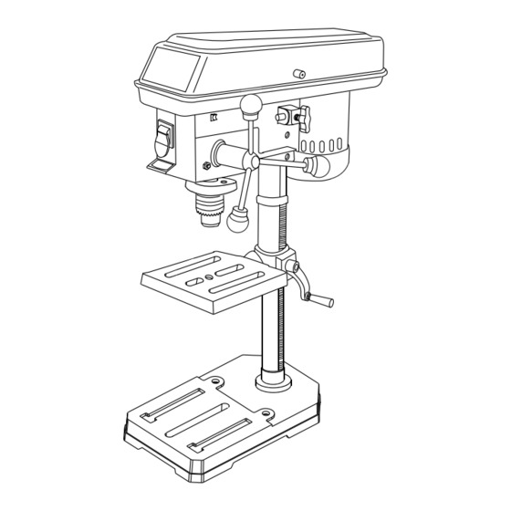
Westward Drill Press feature a heavy cast iron base, column collar, work table and head. Work table height is adjustable using rack
and pinion. Table can be tilted 45° both right and left, and rotates 360° on a vertical axis. Work table surface is precision ground
which features slots for secure, accurate mounting of workpiece and a coolant trough. Other features of the Westward drill press
are an enclosed ball bearing quill assembly, quick belt change and tension mechanism, positive quick-adjust feed depth stop. A
chuck and chuck arbor are included. Westward drill press are ideal for use in home shops, maintenance shops and light industrial
applications. Spindle speeds are adjustable for drilling steel, cast iron, aluminum, wood and plastic.
Unpacking
After unpacking unit, inspect carefully for any damage that may have occurred during transit. Check for loose, missing, or damaged
parts. The drill press is shipped partially assembled. Locate and identify the following assemblies and loose parts: head assembly,
base, column assembly, rack ring and table assembly. Contents of hardware bag includes: Drill chuck, chuck key, rack, feed handles,
worm gear, crank handle, lock handle, hex bolts, 3mm & 4mm hex wrenches and batteries.
IMPORTANT: Many unpainted steel surfaces, such as column and table top, have been coated with a protectant. To ensure proper
fi t and operation, remove coating. Coating is easily removed with mild solvents, such as mineral spirits, and a soft cloth. Avoid
getting solution on paint or any of the rubber or plastic parts. Solvents may deteriorate these fi nishes. Use soap and water on paint,
plastic or rubber components. After cleaning, cover all exposed surfaces with a light coating of oil. Paste wax is recommended for
table top.
WARNING
WARNING
!
If any part is missing or damaged, do not plug the drill press in until the missing or damaged part is
If any part is missing or damaged, do not plug the drill press in until the missing or damaged part is
If any part is missing or damaged, do not plug the drill press in until the missing or damaged part is
If any part is missing or damaged, do not plug the drill press in until the missing or damaged part is
If any part is missing or damaged, do not plug the drill press in until the missing or damaged part is
If any part is missing or damaged, do not plug the drill press in until the missing or damaged part is
replaced, and assembly is complete. Carefully unpack the drill press and all its parts, and compare against the list below.
To protect the drill press from moisture, a protective coating has been applied to the machined surfaces. Remove this
coating with a soft cloth moistened with kerosene or WD-40.
To avoid fi re or toxic reaction, never use gasoline, naphtha, acetone, lacquer thinner or similar highly volatile solvents to
clean the drill press.
REX001
Printed in China
09/06
10",12" Drill Presses
10",12" Drill Presses
1
1KEN3, 1KEN4
1KEN3, 1KEN4
Advertisement
Table of Contents


Need help?
Do you have a question about the 1KEN3 and is the answer not in the manual?
Questions and answers