Advertisement
INSTALLATION INSTRUCTIONS
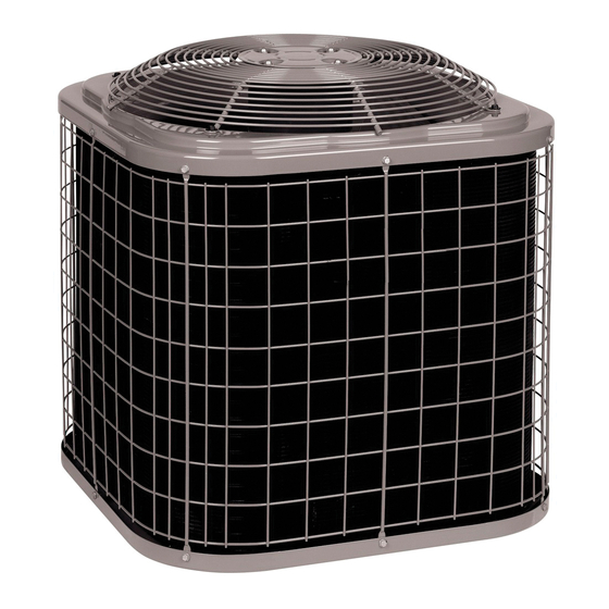
R−410A Split System Air Conditioners
SAFETY CONSIDERATIONS
Improper
installation,
adjustment,
maintenance, or use can cause explosion, fire, electrical
shock, or other conditions which may cause death, personal
injury, or property damage. Consult a qualified installer,
service agency, or your distributor or branch for information
or assistance. The qualified installer or agency must use
factory−authorized kits or accessories when modifying this
product. Refer to the individual instructions packaged with
the kits or accessories when installing.
Follow all safety codes. Wear safety glasses, protective
clothing, and work gloves. Use quenching cloth for brazing
operations. Have fire extinguisher available. Read these
instructions thoroughly and follow all warnings or cautions
included in literature and attached to the unit. Consult local
building codes and current editions of the National Electrical
Code (NEC) NFPA 70. In Canada, refer to current editions of
the Canadian electrical code CSA 22.1.
Recognize safety information. This is the safety−alert symbol
! !
When you see this symbol on the unit and in instructions
or manuals, be alert to the potential for personal injury.
Understand these signal words; DANGER, WARNING, and
CAUTION. These words are used with the safety−alert
symbol. DANGER identifies the most serious hazards which
will result in severe personal injury or death. WARNING
signifies hazards which could result in personal injury or
death. CAUTION is used to identify unsafe practices which
would result in minor personal injury or product and property
damage. NOTE is used to highlight suggestions which will
result in enhanced installation, reliability, or operation.
WARNING
!
ELECTRICAL SHOCK HAZARD
Failure to follow this warning could result in personal
injury or death.
Before installing, modifying, or servicing system, main
electrical disconnect switch must be in the OFF
position. There may be more than 1 disconnect
switch. Lock out and tag switch with a suitable
warning label.
WARNING
!
EXPLOSION HAZARD
Failure to follow this warning could
result in death, serious personal
injury, and/or property damage.
Never use air or gases containing
oxygen
operating refrigerant compressors.
Pressurized mixtures of air or
gases containing oxygen can lead
to an explosion.
NXA6, N4A6, N4A5, R4A5, WCA5, NXA4,
N4A4, R4A4, WCA4, N4A3, R4A3, WCA3
alteration,
service,
for
leak
testing
or
Specifications subject to change without notice.
GENERAL
NOTE: In some cases noise in the living area has been
traced to gas pulsations from improper installation of
equipment.
1. Locate unit away from windows, patios, decks, etc.
where unit operation sound may disturb customer.
2. Ensure that vapor and liquid tube diameters are
appropriate for unit capacity.
3. Run refrigerant tubes as directly as possible by
avoiding unnecessary turns and bends.
4. Leave some slack between structure and unit to
absorb vibration.
5. When passing refrigerant tubes through the wall, seal
opening with RTV or other pliable silicon−based caulk.
(See Fig. 1.)
6. Avoid direct tubing contact with water pipes, duct work,
floor joists, wall studs, floors, and walls.
7. Do not suspend refrigerant tubing from joists and
studs with a rigid wire or strap which comes in direct
contact with tubing.(See Fig. 1.)
8. Ensure that tubing insulation is pliable and completely
surrounds vapor tube.
9. When necessary, use hanger straps which are 1 in.
(25.4 mm) wide and conform to shape of tubing
insulation. (See Fig. 1.)
10. Isolate hanger straps from insulation by using metal
sleeves bent to conform to shape of insulation.
NOTE:
Avoid contact between tubing and structure
OUTDOOR WALL
CAULK
INSULATION
THROUGH THE WALL
HANGER STRAP
(AROUND VAPOR
TUBE ONLY)
1" (25.4 mm) MIN.
SUSPENSION
Fig. 1 − Piping Installation
INDOOR WALL
LIQUID TUBE
VAPOR TUBE
JOIST
INSULATION
VAPOR TUBE
LIQUID TUBE
421 01 5501 02 9/29/15
A94026
Advertisement
Table of Contents

Related Manuals for International comfort products NXA6


Summary of Contents for International comfort products NXA6
- Page 1 INSTALLATION INSTRUCTIONS R−410A Split System Air Conditioners NXA6, N4A6, N4A5, R4A5, WCA5, NXA4, N4A4, R4A4, WCA4, N4A3, R4A3, WCA3 SAFETY CONSIDERATIONS GENERAL Improper installation, adjustment, alteration, service, NOTE: In some cases noise in the living area has been maintenance, or use can cause explosion, fire, electrical...
-
Page 2: Installation
For proper unit operation, check refrigerant charge using overhang within 12 ft. (3.66 m) Position so water, snow, or charging information located on control box cover and/or in ice from roof or eaves cannot fall directly on unit. the Check Charge section of this instruction. NOTE: 18”... - Page 3 shown in Table 1 are recommended up to 80 ft. (24.38 m). Install Liquid−Line Filter Drier Indoor See Specification Sheets for acceptable alternate vapor CAUTION diameters and associated capacity losses. For tubing requirements beyond 80 ft. (24.38 m), substantial capacity performance losses occur.
- Page 4 Final Tubing Check Units with Indoor Piston Units installed with indoor pistons require charging by the IMPORTANT: Check to be certain factory tubing on both superheat method. indoor and outdoor unit has not shifted during shipment. Ensure tubes are not rubbing against each other or any The following procedure is valid when indoor airflow is within sheet metal or wires.
- Page 5 Table 2 – Rating Plate (required) Subcooling Temperatures R-410A Required Liquid Line Temperature _F (_C) Measure Liquid Pressure (_C) (_C) (_C) (_C) (_C) (_C) (psig) Table 3 – Superheat Charging − AC Only EVAPORATOR ENTERING AIR TEMPERATURE (_F WB) OUTDOOR TEMP (_F) —...
-
Page 6: Make Electrical Connections
Table 4 – Required Suction−Line Temperature SUCTION PRESSURE AT SERVICE PORT (PSIG) SUPERHEAT TEMP (_F) 107.8 112.2 116.8 121.2 130.8 138.8 140.8 145.8 Make Electrical Connections Connect Ground and Power Wires Connect ground wire to ground connection in control box for Be sure field wiring complies with local and national fire, safety. - Page 7 Final Wiring Check IMPORTANT: Check factory wiring field wire connections to ensure terminations are secured properly. Check wire routing to ensure wires are not in contact with tubing, sheet metal, etc. Compressor Crankcase Heater When equipped with a crankcase heater, furnish power to heater a minimum of 24 hr before starting unit.
-
Page 8: Final Checks
15 ft. (4.57 m) Line Set Charge lb (kg) SOUTHWEST/NORTH SOUTHWEST Unit 14 SEER SOUTHWEST 16 SEER 16 SEER Size COASTAL 14/15 SEER 13 SEER 14 SEER 4.10 (1.86) 4.77 (2.16) 4.5 (2.04) 4.87 (2.21) 4.61 (2.09) 3.83 (1.74) 4.22 (1.91) 4.20 (1.91) 4.20 (1.91) 4.60 (2.09) - Page 9 S Do not vent R−410A refrigerant into the atmosphere. S Do not use capillary tube coils. S Observe all warnings, cautions, and bold text. Copyright 2015 International Comfort Products Lewisburg, TN 37091 USA 421 01 5501 02 Specifications subject to change without notice.
Need help?
Do you have a question about the NXA6 and is the answer not in the manual?
Questions and answers