Table of Contents
Advertisement
Dear Customer,
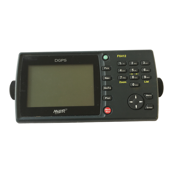
Thank you for choosing the MLR FX312 GPS or the MLR FX412 DGPS Navigator. We are
confident it will give you many years of excellent service and you will enjoy exploring the
numerous functions available from this state of the art GPS or DGPS.
For further information or technical help, please do not hesitate to contact your local dealer or
MLR Electronique in Vallet, who will be pleased to help you.
If you have chosen the FX312, you will be able to upgrade its accuracy by connecting it to the
MLR DF300 Differential Beacon Receiver, or by modifying it into a FX412. For more
information, contact your local dealer.
Yours sincerely,
Jean Pierre MAQUAIRE
C.E.O
FX312 & FX412 VERSION 2.0
MLR ELECTRONIQUE
1
Advertisement
Table of Contents


Need help?
Do you have a question about the FX312 and is the answer not in the manual?
Questions and answers