Table of Contents
Advertisement
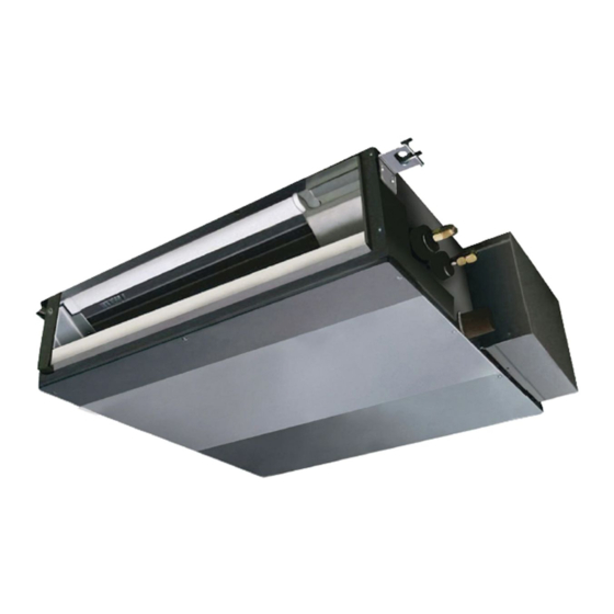
SPLIT-TYPE, HEAT PUMP AIR CONDITIONERS
TECHNICAL & SERVICE MANUAL
Series SEZ
Indoor unit
[Model names]
SEZ-A12AR
SEZ-A18AR
SEZ-A24AR
INDOOR UNIT
CENTRALLY CONTROLLED
CHECK
STAND BY
DEFROST
TEMP.
WIRED REMOTE
CONTROLLER
Ceiling Concealed
[Service Ref.]
SEZ-A12AR.TH
SEZ-A18AR.TH
SEZ-A24AR.TH
Model name
indication
1Hr.
ON OFF
˚C
CLOCK
FILTER
CHECK MODE
˚C
TEST RUN
ERROR CODE
NOT AVAILABLE
FUNCTION
ON/OFF
R410A
Revision :
• " 2. SPECIFICATIONS " has
been modified.
Note :
•This manual does not cover the
following outdoor units. When
servicing them, please refer to
the service manual No.OC304
REVISED EDITION-A and this
manual in a set.
• Please void OC303.
CONTENTS
1. PART NAMES AND FUNCTIONS ········3
2. SPECIFICATIONS·································5
3. OUTLINES AND DIMENSIONS············8
4. WIRING DIAGRAM·······························9
5. REFRIGERANT SYSTEM DIAGRAM ······10
6. TROUBLESHOOTING ························11
7. DISASSEMBLY PROCEDURE···········18
8. PARTS LIST········································21
9. OPTIONAL PARTS ·····························23
No.OC303
REVISED EDITION-A
Advertisement
Table of Contents
Troubleshooting

Related Manuals for Mitsubishi SEZ-A12AR


Summary of Contents for Mitsubishi SEZ-A12AR
-
Page 1: Table Of Contents
R410A Series SEZ Indoor unit Revision : • “ 2. SPECIFICATIONS ” has [Model names] [Service Ref.] been modified. SEZ-A12AR.TH SEZ-A12AR Note : SEZ-A18AR.TH •This manual does not cover the SEZ-A18AR following outdoor units. When SEZ-A24AR.TH servicing them, please refer to SEZ-A24AR the service manual No.OC304... - Page 2 Revision: “ 2. SPECIFICATIONS ” has been modified on page 5 and 6. Page Revise point Service Ref. Incorrect Correct Electrical date SEZ-A12AR.TH Power input SEZ-A18AR.TH Rated frequency SEZ-A24AR.TH...
-
Page 3: Part Names And Functions
PART NAMES AND FUNCTIONS Indoor Unit SEZ-A12AR.TH SEZ-A18AR.TH SEZ-A24AR.TH Air outlet Air outlet duct flange Air inlet (Selecting the either back side or bottom side) Wired remote controller On the controls are set, the same operation mode can be repeated by simply pressing the ON/OFF button. -
Page 4: Operation Lamp
Display In this display example on the bot- CENTRALLY CLOCK display tom left, a condition where all dis- CONTROLLED display play lamps light is shown for expla- The current time , start time and stop nation purposes although this differs time can be displayed in ten second This indicates when the unit is con- intervals by pressing the time switch... -
Page 5: Specifications
W.B. 6: Refrigerant piping length (one way): 5m 1 Measured under rated operating frequency. Specifications and rating conditions of main electric parts INDOOR UNIT Model SEZ-A12AR.TH SEZ-A18AR.TH SEZ-A24AR.TH Item Indoor fan capacitor (C1) SEZ-A12/18AR.TH : 2.5+ 440V SEZ-A24AR.TH : 3.0+ 440V... - Page 6 Indoor model SEZ-A24AR.TH Function Cooling Heating Single phase Power supply 230V, 50Hz Capacity Air flow (High/Low) K /h 1200/720 Power outlet Running current 0.34 Power input Rated frequency Auxiliary heater A(kW) — Power factor Fan motor current 0.34 Model PK6V50-EF WHT-BLK : 101.1 BLK-BLU : 56.1 Winding...
-
Page 7: Noise Criterion Curves
NOISE CRITERION CURVES <50Hz> <50Hz> SEZ-A12AR.TH SEZ-A18AR.TH NOTCH LINE SPL(dB) NOTCH SPL(dB) LINE NC-70 NC-70 NC-60 NC-60 NC-50 NC-50 NC-40 NC-40 NC-30 NC-30 APPROXIMATE APPROXIMATE TERESHOLD OF TERESHOLD OF HEARING FOR HEARING FOR NC-20 NC-20 CONTINUOUS CONTINUOUS NOISE NOISE 1000... -
Page 8: Outlines And Dimensions
OUTLINES AND DIMENSIONS SEZ-A12AR.TH Unit : mm SEZ-A18AR.TH SEZ-A24AR.TH In case of bottom side suction, Air inlet (rear side) dimensions Air inlet (bottom side) dimensions mount the PLATE (A) on the rear side. PLATE (A) After installation, remove the (Inlet size) transportation support PLATE (B). -
Page 9: Wiring Diagram
WIRING DIAGRAM SEZ-A12AR.TH SEZ-A18AR.TH SEZ-A24AR.TH CIRCUIT BREAKER CND(POWER) CN29 (2 PHASE) RT13 CN21 FUSE GRN/YLW (LIQUID) RT12 POWER SUPPLY CN20 ZNR1 (INTAKE) 220-240V 220V 50Hz 60Hz RT11 TRANS DC13.1V 12VDC FAN1 (FAN) FOR A12 (1:1 SYSTEM) 220-240V~ 2 TO OUTDOOR... -
Page 10: Refrigerant System Diagram
REFRIGERANT SYSTEM DIAGRAM SEZ-A12AR.TH SEZ-A18AR.TH SEZ-A24AR.TH Strainer Heat exchanger Refrigerant GAS pipe connection (Flare) Condenser/evaporator temperature thermistor (RT13) Refrigerant flow in cooling Refrigerant flow in heating Refrigerant LIQUID pipe connection (Flare) Pipe temperature thermistor/liquid Room temperature (RT12) thermistor (RT11) Strainer... -
Page 11: Troubleshooting
TROUBLESHOOTING 6-1. Cautions on troubleshooting (1) Before troubleshooting, check the followings: 1 Check the power supply voltage. 2 Check the indoor/outdoor connecting wire for mis-wiring. (2) Take care the followings during servicing. 1 Before servicing the air conditioner, be sure to first turn off the remote controller to stop the main unit, and then turn off the breaker. -
Page 12: Trouble Shooting
6-3. Trouble shooting (1) In case of being indicated irregularity on the self diagnoses Check Phenomenon Cause Countermeasure code 6800 Mis-wiring Wiring between the indoor and Check the wiring out between the indoor and outdoor is coming off. outdoor. Difference of wiring polarity between the indoor and outdoor. - Page 13 (2) Other case Phenomenon Cause Countermeasure Not working of remote A connector attaching the panel to the body Connect it. controller switch ON/OFF is not connected. Short circuit the protecting parts in the Check the varistor (ZNR1) and fuse (FUSE) out in Indoor controller board.
- Page 14 Check of indoor controller board and indoor fan motor Check code : 6800 Error was found in the signal transmitted or received between the indoor and outdoor units. Are there any devices emitting Is the connecting wire between noise near the power supply or the indoor and outdoor units the connecting wire between the connected properly?
- Page 15 Check code : 5102 Refer to the TECHNICAL & SERVICE MANUAL of Is the error of indoor unit? outdoor unit. Check the condenser/evaporator Check the pipe temperature temperature thermistor. thermistor / liquid. Is the connector CN29 on the Is the connector CN21 on the indoor controller board connected? indoor controller board connected? Measure the resistance of...
- Page 16 6-4. Test point of indoor controller board Indoor controller board Pipe temperature thermistor/liquid (RT12) Condenser/evaporator Room temperature thermistor (RT11) temperature thermistor (RT13) Drain sensor (DS) •Room temperature thermistor (RT11) •Pipe temperature thermistor/liquid (RT12) •Condenser/evaporator temperature thermistor (RT13) < Thermistor for lower temperature > Power supply input 220-240V AC Fuse 250V AC 3.15A...
-
Page 17: Trouble Criterion Of Main Parts
6-5. Trouble criterion of main parts SEZ-A12AR.TH SEZ-A18AR.TH SEZ-A24AR.TH Part name Check method and criterion Room temperature Measure the resistance with a tester. thermistor (Part temperature 10°C ~ 30°C) (RT11) Normal Abnormal Pipe temperature 8kΩ~20kΩ Opened or short-circuited thermistor/liquid (RT12) -
Page 18: Disassembly Procedure
DISASSEMBLY PROCEDURE SEZ-A12AR.TH SEZ-A18AR.TH SEZ-A24AR.TH OPERATING PROCEDURE PHOTOS Service panel Photo 1. Electrical (Pipe temperature 1. Removing the electrical parts parts cover thermistor / liquid) (1) Remove the 2 screws and the electrical parts cover. (See Photo 1.) Indoor controller board (I.B) - Page 19 OPERATING PROCEDURE PHOTOS 4. Removing the room temperature thermistor (RT11) Photo 5. (1) Remove the electrical parts cover. Motor bands Fan casing Claws (Refer to 1.) (2) Remove the front panel at fan side. (12 screws) (See Photo 1.) (3) Remove the thermistor (RT11) from the separator (panel). (See Photo 6.) (4) Disconnect the connector (CN20)from the indoor controller board and pull the lead wire of...
- Page 20 OPERATING PROCEDURE PHOTOS 6. Removing the drain pan (1) Unscrew each set screw on the right and left, and remove the drain pan pushing it toward the the back. (See Photo 1.) Photo 8. Screws 7. Removing the heat exchanger (1) Remove the drain pan.
-
Page 21: Parts List
PARTS LIST INDOOR UNIT STRUCTURAL PARTS SEZ-A12AR.TH SEZ-A18AR.TH SEZ-A24AR.TH Part number that is circled is not shown in the illustration. Q'ty/set Price Wiring Recom- Specification Remarks Parts No. Parts name SEZ- Diagram mended Unit Amount (Drawing No.) Symbol Q'ty A12AR.TH A18AR.TH... - Page 22 INDOOR UNIT ELECTRICAL PARTS SEZ-A12AR.TH SEZ-A18AR.TH SEZ-A24AR.TH CENTRALLY CONTROLLED 1Hr. ON OFF ˚C CHECK CLOCK FILTER CHECK MODE ˚C TEST RUN STAND BY ERROR CODE NOT AVAILABLE FUNCTION DEFROST TEMP. ON/OFF Part numbers that is circled is not shown in the illustration.
-
Page 23: Optional Parts
Please use the optional extension pipe as follows. Additional Pipe size O.D.mm (in.) refrigerant Applied unit Models Pipe length charge Insulation Cross-section A-Gas B-liquid R410A (g) MAC-680PI MAC-681PI 9.52 SEZ-A12AR.TH MAC-682PI (3/8) MAC-683PI MAC-684PI MAC-670PI MAC-671PI 6.35 12.7 SEZ-A18AR.TH MAC-672PI (1/4) (1/2) MAC-673PI MAC-674PI MAC-860PI MAC-861PI 15.88... - Page 24 HEAD OFFICE : MITSUBISHI DENKI BLDG., 2-2-3, MARUNOUCHI, CHIYODA-KU, TOKYO 100-8310, JAPAN CCopyright 2004 MITSUBISHI ELECTRIC ENGINEERING CO., LTD. Distributed in Sep. 2004 No. OC303 REVISED EDITION-A PDF 8 Distributed in Mar. 2004 No. OC303 PDF 8 New publication, effective Sep. 2004.
Need help?
Do you have a question about the SEZ-A12AR and is the answer not in the manual?
Questions and answers