
Subscribe to Our Youtube Channel
Related Manuals for Bad Boy Outlaw Stand-On BBS 3600


Summary of Contents for Bad Boy Outlaw Stand-On BBS 3600
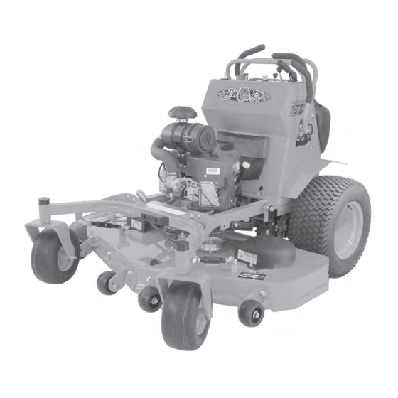
- Page 1 OUTLAW STAND-ON MODEL ZERO-TURN MOWER OWNER’S, SERVICE & PARTS MANUAL For additional information, please see us at www.badboymowers.com Bad Boy, Inc. 102 Industrial Drive Batesville, Arkansas 72501 ©2015 12-11...
-
Page 2: Table Of Contents
TABLE OF CONTENTS Basic Information ....................Section 1 (page 4) Bad Boy Safety Guidelines ................Section 2 (pages 5–8) Operation ......................Section 3 (pages 9) Maintenance ...................... Section 4 (page 10) Storage and Transportation ................Section 5 (page 12) Troubleshooting and FAQ ..................Section 6 (page 13) Controls ...................... - Page 3 Inner Air Filter Outer Air Filter Air Filter 063-8020-00 063-8019-00 Motor Oil 10W-30 Motor Oil - Bad Boy Synthetic Blend Motor Oil Recommended Hydraulic 20W-50 Motor Oil - Bad Boy Hydrostatic Oil Recommended Approximately 2 quarts per side PAGE 3...
- Page 4 If an evaporative emission control system component does fail in a manner that would cause the equipment to no longer meet the requirements of 40 CFR 1060 within the first two years Bad Boy Inc. will replace the defective component. Your evaporative emission control system may include parts such as fuel tanks, fuel lines, carbon canisters, fuel caps, valves, vapor hoses, clamps, or connectors.
-
Page 5: General Operation
SECTION 2: MOWER SAFETY GUIDELINES Never allow untrained people to operate this machine. It is the owner’s responsibility to get training and see to it that anyone who has permission to use your machine receives the proper training. Do not mow around people. The factory discharge chute is designed to deflect debris downward, but it could be possible for debris to be thrown in a way that can cause damage to people or property. -
Page 6: Slope Operation
SLOPE OPERATION Slopes are a major factor related to loss of control and tip over accidents, which can result in severe injury or death. Operation on all slopes requires extra caution. If you cannot back up the slope, or you feel uneasy on it, do not mow it. 2.22 Mow up and down slopes, not across. - Page 7 SERVICE: SAFE HANDLING OF GASOLINE To avoid personal injury or property damage, use extreme care in handling gasoline. Gasoline is extremely flammable and the vapors are explosive. 2.45 Extinguish all cigarettes, cigars, pipes, and all other sources of ignition. 2.46 Use only an approved gasoline container. 2.47 Never remove gas cap or add fuel with the engine running.
-
Page 8: Safety Interlock System
SAFETY INTERLOCK SYSTEM Your Bad Boy mower is equipped with a safety interlock system. This system is designed to prevent serious injury or death to the operator and other people or property damage. The system consists of an operator presence switch in the seat, the parking brake, drive lever neutral position, the mower blade engagement switch, and the ignition switch. -
Page 9: Mower Operation
The machine could lose traction on a decline or tip backwards on an incline. 3.12 Once you become comfortable with your Bad Boy Mower you will notice your overall mowing time will decrease. - Page 10 SECTION 4: MOWER MAINTENANCE Interval First Every 50 Every 100 Every Daily hours or hours or Section Maintenance hours annually* annually* hours Check and add engine oil ● Section 3 Section 2 Check all belts for proper alignment ● (Pump) 6 (Deck) Check tire pressure and wheel lug ●...
- Page 11 Maintenance Log Date: Hours: Performed: Performed Date: Hours: Date: Hours: Performed: Performed Date: Hours: Performed Date: Hours: Date: Hours: Performed: Performed Date: Hours: Date: Hours: Performed: Performed Date: Hours: Performed Date: Hours: Performed: Date: Hours: Date: Hours: Performed: Performed Date: Hours: Performed Date:...
- Page 12 SECTION 5: MOWER STORAGE & TRANSPORTATION Keep machine from collecting debris by storing in a covered area while not in use. 5.2 Fuel can harm your machine if left for more than 30 days without changing, especially if the fuel contains ethanol. Never use fuel with more than 10% ethanol by volume. E-15 is not permitted.
- Page 13 SECTION 6: TROUBLESHOOTING Q: How do I prevent an uneven cutting pattern and increase the quality of cut? A: Check tire pressure, check blade sharpness (replace blades or sharpen at least once per year or when needed), make sure blades are tightened properly, check spring and belt tension, check the underside of the deck to ensure the mower deck is free of grass build-up and debris, make sure your machine is at full throttle, and vary your mowing pattern each time you cut your grass.
- Page 14 SECTION 7: CONTROLS Ignition Switch—Bad Boy Mowers have a three position ignition switch: off, run, and start. With key inserted, rotate it clockwise to START position and release key when engine starts, and switch will automatically return to he RUN position.
- Page 15 By pushing the arms in the mower can be put in a neutral position. Return the arms to the “forward position for normal operation. 8.4 Your Bad Boy Mower Weighs: OUTLAW STAND-ON: 897 lbs *** Weights fluctuate with the addition of accessories.
-
Page 16: Mower Blade Maintenance
SECTION 10: MOWER BLADE MAINTENANCE 10.1 Check mower blades after each use. This is essential for maintaining well-groomed turf. Keep the blades sharp. If a dull blade is used for cutting, the grass will tear rather than cut. This could damage the grass leaving a brown frayed top on the grass within a few hours. A dull blade will also require more power from the engine. -
Page 17: How To Choose The Right Blade
HOW TO CHOOSE THE RIGHT BLADE Essentially there are only TWO basic styles of mowing blades used or approved for use on our current products: 1) The standard style of mowing blade is essentially designed for cutting grass and effectively discharging the clippings out from the deck to fall onto the lawn or to be captured in a grass collection system. -
Page 18: Mowing Tips
MOWING TIPS: • Mow header strips at the ends of the lawn and around flower beds first. Make them wide enough that you can turn the mower around in the already mown section. Then mow back and forth between these header strips overlapping each lap by about 1/8 the width of the mower’s deck. -
Page 19: Service Section
This will allow the transaxles to vent during oil fill and prevent any air lock within the transaxles. 10) Fill with 20W-50 motor oil (Bad Boy Hydrostatic oil is recommended) through the hydraulic fluid reservoirs until it just appears at the bottom of each transaxle’s top port (approximately 2 quarts per transaxle, 4 quarts total). - Page 20 11) Install and torque the top port plugs to 180 in. lbs. (20.3 Nm). 12) Continue to fill the transaxle through the hydraulic fluid reservoirs until the “Full Cold” line is reached on the hydraulic fluid reservoirs. 13) Re-install the caps on the hydraulic fluid reservoirs. 14) Now we need to purge the air from the transaxle.
- Page 21 SECTION 2: DRIVE BELT Shown on the right is a typical pump belt tensioner for your model mower. This is how you can adjust the belt pump belt tension on your mower. There are two jam nuts on an all thread that need to be adjusted in ordered to change the tension in the spring.
- Page 22 Kawasaki FX691V and FX730V This machine has an oil drain hose installed on the engine to allow for easier oil changes. Bad Boy recommends that the oil and filter be changed at intervals of 50 usage hours or yearly, whichever occurs first.
- Page 23 The fuel filter is located in the fuel line on the left side of the engine by the starter motor. Replace the filter yearly. Prior to the removal of the old filter, note the direction of fuel flow as indicated on the filter. Have towels readily available in order to quickly remove any fuel leakage.
- Page 24 The air cleaner is the engine’s only defense against damaging foreign particles. It is very important that the air cleaner element is inspected prior to each use. Remove the element and tap its sides in order to remove debris. Do not blow the filter out using compressed air.
- Page 25 3.4 Changing the spark plugs and checking the spark plug gap: 1) Remove the wire on the spark plug and use a 13/16” socket to remove the spark plug. 2) Check the gap on the spark plug to verify that it is 0.03 in using a feeler gauge.
- Page 26 If either fuse is repeatedly blowing, contact your Bad Boy dealer. Always check the condition of the wiring harness ground cable. Ensure that the ground is connected, clean, and tight.
- Page 27 PAGE 27...
- Page 28 SECTION 5: FRAME The front fork nuts require a torque of 40ft-lbs. While applying this torque, turn the fork itself to ensure no damage is done to the bearing. This operation is only necessary if a repair requires it. Torque rear wheel lugs to 65-75 ft. lbs. Re-torque at every oil change and check at every mowing.
- Page 29 SECTION 6: CUTTING DECK Deck belt removal 1) Remove ignition key. 2) Raise the deck to its highest position. 3) Remove the right pulley cover. 4) While lifting up on the belt (as shown in the photograph), rotate the pulley until the belt is free of the pulley.
- Page 30 Leveling the Deck 1) Start on a flat level surface and set the air pressure in all four tires to 12 psi. 2) Raise the deck u p, and measure all f our corners of the deck to see i f i t i s l evel f rom left to right and front to back.
- Page 31 The deck spring tension is critical. If the tension is too high, premature failure of the deck belt and blade spindles can occur. If the tension is too low, the belt can ‘jump off’ or slip on the pulleys. This results in reduced cut quality and early belt failure.
- Page 32 Blade Removal: To change blades, it may be easier to use a piece of wood to keep the blade from turning so that the bolt can be loosened. Use a 15/16” socket and impact Drill, or a wrench and an extension to gain more leverage.
-
Page 33: Parts Section
PARTS SECTION Front Fork Assembly Parts List ITEM PART NUMBER DESCRIPTION 023-7913-00 Front Fork 012-7003-00 Seal 013-8050-00 1/2-13 Nylon Flange Nut 018-7010-00 1/2" x 9" GR 5 Hex Bolt 014-7005-00 Dust Cover 010-7001-00 Bearing 022-2006-00 Tire and wheel assembly 025-5202-00 Front Wheel Spanner 022-7009-00 1 3/8"... - Page 34 DETAIL B PAGE 34...
- Page 35 Parts List ITEM PART NUMBER DESCRIPTION 070-5220-00 2015 Stand-On Frame 070-9048-00 48" Front End (2015 Stand-On) 018-5043-00 3/8" x 1 1/4" Carriage Bolt 013-5041-00 3/8 Nylock Nut 024-6034-00 1/4" Press in Grease Fitting 017-9000-00 Two Piece Pillow Block (Male) 017-9050-00 Two Piece Pillow Block (Female) 017-9025-00 Two Piece Pillow Block Strap...
- Page 36 DETAIL A DETAIL D DETAIL E DETAIL B DETAIL C PAGE 36...
- Page 37 Parts List ITEM PART NUMBER DESCRIPTION 079-4110-00 2015 Podium Panel Left 079-4050-00 Door Panel Assembly 079-4105-00 2015 Podium Panel Right 074-0050-00 Fender (Right Side) 074-0060-00 Fender (Left Side) 018-8065-00 5/16" x 1" Carriage Bolt 039-0070-00 Back Cover Hinge Bracket 067-8090-00 350ml Expansion Tank 066-8076-00 Fuel Cap...
- Page 38 Parts List ITEM PART NUMBER DESCRIPTION 079-4110-00 2015 Podium Panel Left 079-4105-00 2015 Podium Panel Right 079-4100-00 2015 Podium Front Panel 069-2012-00 Brake Handle- Stand On 018-5344-00 5/16" x 2 1/2" Bolt 025-0011-00 Brake/Latch Spacer-Stand On 018-8058-00 10-24 x 1 BS C/S 18-8 SS 055-8021-00 Throttle-All Outlaws 054-8017-00...
- Page 39 Welded to Frame DETAIL A Welded to Frame PAGE 39...
- Page 40 Parts List ITEM PART NUMBER DESCRIPTION 031-7120-00 Support Handle Stand Up (Front & Back) 031-7130-00 Left Steering Handle Assembly 031-7140-00 Right Steering Handle Assembly 039-0210-00 Safety Kill Switch Assembly Bracket 032-5002-00 Stand On Flange Bushing-Steering Arms 013-5019-00 #10 Nylock Nut 018-5200-00 1024 X 5/8"...
- Page 41 Stand-On Transaxle Assembly DETAIL A DETAIL B PAGE 41...
- Page 42 Parts List ITEM PART NUMBER DESCRIPTION 050-6000-00 Left 3400 Transaxle 050-2081-00 Left 3100 Transaxle (36" Stand-On only) 050-6001-00 Right 3400 Transaxle 050-2080-00 RIght 3100 Transaxle (36" Stand-On only) 028-4802-00 Crossover Bar for ZT 2016 018-3000-00 3/8'' x2'' Hex Bolt 018-4701-00 5/16"...
- Page 43 Kawasaki FX-730V FX-691V Parts List ITEM PART NUMBER DESCRIPTION 015-0691-00 FX-691V 015-0730-00 FX-730V 063-8017-00 Kawasaki Oil Filter 042-5020-00 1/4 x 2 Square key Stock 033-5035-00 4 3/4 Motor Pulley 070-1000-00 Clutch Assembly 018-5300-00 7/16" x 2 1/2" Hex Bolt 019-8053-00 7/16"...
- Page 44 36" Deck Assembly PAGE 44...
- Page 45 Parts List ITEM PART NUMBER DESCRIPTION 060-1136-00 36 Stand On Deck 037-2000-00 Spindle Assembly 018-5040-00 3/8" x 1 1/4" Hex Bolt 019-5037-00 3/8" Lock Washer 013-6014-00 3/8" Hex Nut 033-4820-00 Deck Pulley 025-0060-00 36 Deck Spindle Spacer 025-5339-00 1 3/4" Pulley Spacer 039-6945-00 Deck Idler 025-7036-00...
- Page 46 Stand-On 48" Deck On Right Side Spindle Only DETAIL B DETAIL A PAGE 46...
- Page 47 Parts List ITEM PART NUMBER DESCRIPTION 060-1148-00 48" 2015 Stand-On Deck (Welded Assembly) 018-6059-00 5/8" x 2 1/2" Hex Bolt 013-7021-00 5/8 Std NC Nylock Nut 018-6037-00 1/2-13X 2-1/4 GR Hex Bolts 013-8050-00 1/2-13 Nylon Flange Nut 025-5338-00 .502 ID X .750 OD X 1.500 Long Spacer 018-2018-00 1/2 x 3 1/2 Flange Bolt Grade 8 033-5000-00...
- Page 48 Stand-On 54" Deck On Right Side DETAIL A Spindle Only DETAIL B PAGE 48...
- Page 49 Parts List ITEM PART NUMBER DESCRIPTION 060-1154-00 54" 2015 Stand-On Deck (Welded Assembly) 018-6059-00 5/8" x 2 1/2" Hex Bolt 013-7021-00 5/8 Std NC Nylock Nut 018-6037-00 1/2-13X 2-1/4 GR Hex Bolts 031-6020-00 Deck Arm Assembly 013-8050-00 1/2-13 Nylon Flange Nut 018-1090-00 1/2"...
- Page 50 Stand-On 61" Deck On Right Side Spindle Only DETAIL B DETAIL A PAGE 50...
- Page 51 Parts List ITEM PART NUMBER DESCRIPTION 060-1161-00 61" 2015 Stand-On Deck (Welded Assembly) 018-6059-00 5/8" x 2 1/2" Hex Bolt 013-7021-00 5/8 Std NC Nylock Nut 018-6037-00 1/2-13X 2-1/4 GR Hex Bolts 031-6020-00 Deck Arm Assembly 013-8050-00 1/2-13 Nylon Flange Nut 018-1090-00 1/2"...
- Page 52 037-2000-00 Spindle Assembly Parts List 36" Deck Only ITEM PART NUMBER DESCRIPTION 037-6027-00 Spindle Housing 037-6028-00 Spindle Spacer-Component 037-6025-00 Spindle Shaft 037-6024-00 Spindle Bearing 037-4000-50 Double Bearing Spindle Parts List ITEM PART NUMBER DESCRIPTION 037-4001-00 4000 Series Spindle Housing 037-4002-00 4000 Series Spindle Spacer 037-9050-00 Locking Collar w/ 1/4"-20 Set Screw...
- Page 53 PAGE 53...
-
Page 54: Limited Warranty
The leading edge of the deck shell will be warranted for the entire lifetime of the machine to the original purchaser against defects in materials and workmanship. Labor required to repair or replace the leading edge of the deck shell will be covered by Bad Boy Inc. for two years and at the unit owner’s expense during the balance of the lifetime of the machine. - Page 55 Bad Boy, Inc. 102 Industrial Drive Batesville, AR 72501 www.badboymowers.com Technical Support: ............techsupport@badboymowers.com Warranty: ..................warranty@badboymowers.com Parts: ....................partsdept@badboymowers.com WARRANTY REGISTRATION Ensure selling dealership has registered mower within 30 days of purchase to validate warranty. Please record your serial number, date of purchase and dealership information for your records.
- Page 56 For additional information, please see us at www.badboymowers.com Bad Boy, Inc. 102 Industrial Drive Batesville, Arkansas 72501...
Need help?
Do you have a question about the Outlaw Stand-On BBS 3600 and is the answer not in the manual?
Questions and answers