Table of Contents
Advertisement
Quick Links
Download this manual
See also:
User Manual
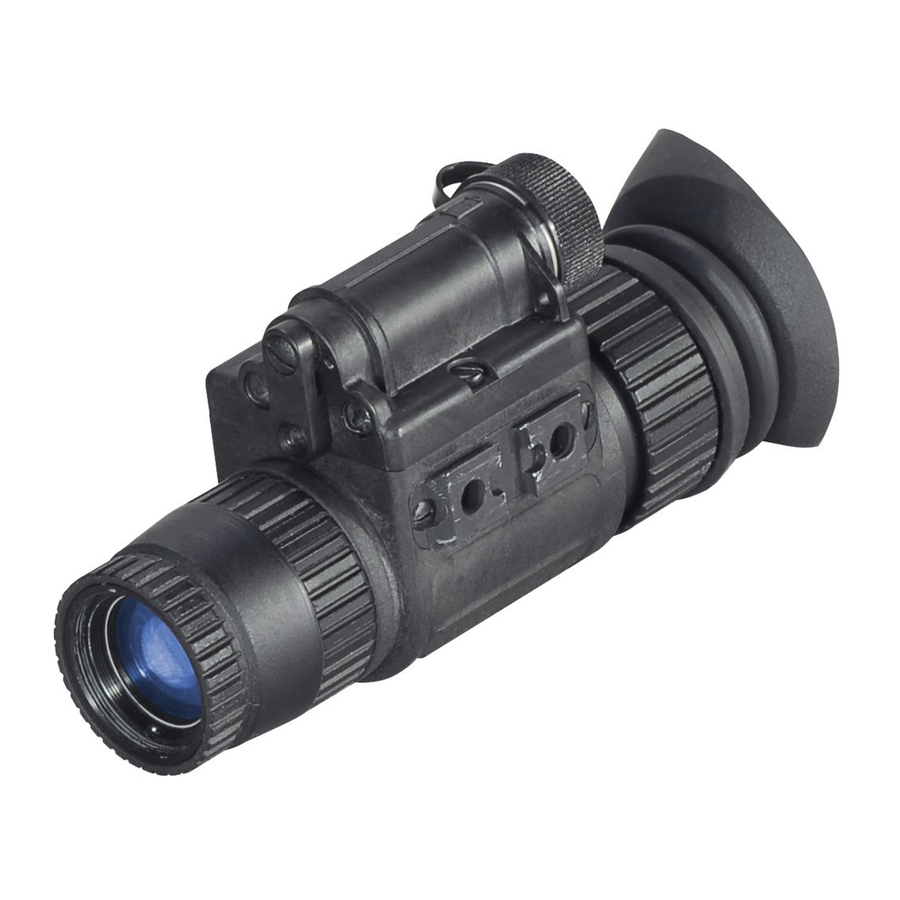
ATN NVM14
Mfg's P/Ns:
ATN NVM-14-2 (Gen2+)
ATN NVM-14-2I (Gen2+)
ATN NVM-14-CGT (Gen2+)
ATN NVM-14-HPT (Gen2+)
ATN NVM-14-3 (Gen3)
ATN NVM-14-3A (Gen3)
ATN NVM-14-4 (Gen4)
o p e r a t o r s ' s m a n u a l
Important Export Restrictions! Commodities, prod-
ucts, technologies and services contained in this manual
are subject to one or more of the export control laws and
regulations of the U.S. Government and they fall under the
control jurisdiction of either the US Department of State
or the US BIS-Department of Commerce. It is unlawful
and strictly prohibited to export, or attempt to export or
otherwise transfer or sell any hardware or technical data
or furnish any service to any foreign person, whether
abroad or in the United States, for which a license or writ-
ten approval of the U.S. Government is required, without
first obtaining the required license or written approval
from the Department of the U.S. Government having
jurisdiction. Diversion contrary to U.S. law is prohibited.
Advertisement
Table of Contents

Related Manuals for ATN ATN Night Shadow 3


Summary of Contents for ATN ATN Night Shadow 3
- Page 1 ATN NVM14 Mfg’s P/Ns: ATN NVM-14-2 (Gen2+) ATN NVM-14-2I (Gen2+) ATN NVM-14-CGT (Gen2+) ATN NVM-14-HPT (Gen2+) ATN NVM-14-3 (Gen3) ATN NVM-14-3A (Gen3) ATN NVM-14-4 (Gen4) o p e r a t o r s ’ s m a n u a l...
- Page 2 Manual (NVM14-003) Revision 1 - December 2006 The information in this manual furnished for information use only, is subject to change without notice, is not to be construed as a commitment by ATN Corp. ATN Corp. assumes no responsibility or liability for any errors or inaccura- cies that may appear in this book.
-
Page 3: Safety Summary
SAFETY SUMMARY CAUTIONS • The ATN NVM-14 is a precision optical instrument and must be handled carefully at all times to prevent damage. • Do not scratch the external lens surfaces or touch them with your fingers. • Wiping demisting shield with lens paper while wet or with wet lens paper can damage the coating. - Page 4 NOTES • When utilizing the ATN NVM-14 for driving purposes, the gog- gles may not be used in the hand-held mode. The goggles must be worn in the head- or helmet-mounted position. • At operating temperatures below –20°C (-4°F), alkaline bat- teries are not recommended, as operating life will be severely reduced.
-
Page 5: Equipment Limitations
EqUIpMENT LIMITATIONS To avoid physical and equipment damage when using the ATN NVM-14, carefully read and understand the following safety pre- cautions. • The equipment requires some night light (moonlight, starlight, etc.) to operate. The level of performance depends upon the level of light. -
Page 6: Table Of Contents
TABLE OF CONTENTS Section Section I Appendix A Appendix B Title Safety Summary Table Of Contents List of Figures List of Tables How To Use This Manual General Information Equipment Description Mounting Procedures Operating Procedures Operational Defects Maintenance End Item Components Repair Parts List Index For Technical Information... -
Page 7: List Of Figures
Attaching ATN NVM-14 to Weapon Mount Mounting the ATN NVM-14 to a scope Adapter for using ATN 3.5x26 scope Mounting the Picatinny Adapter to the ATN NVM-14 3-6 Attaching ATN NVM-14 to PVS-7 Adapter Attaching ATN NVM-14 to PVS-7 Headmount... -
Page 8: List Of Tables
LIST OF TABLES Table Title ATN NVM-14DNS Major Components Battery Life Preventive Maintenance Checks and Service for the ATN NVM-14 Operator Troubleshooting for the ATN NVM-14 ATN NVM-14 End Item Components ATN NVM-14 Repair Parts List page... -
Page 9: How To Use This Manual
HOW TO USE THIS MANUAL USAGE You must familiarize yourself with the entire manual before operating the equipment. Read the complete maintenance task before performing maintenance and follow all WARNINGS, CAUTIONS, and NOTES. MANUAL OVERVIEW The manual contains sections for Operating and Maintaining the Day Night SightMulti-Use Minimonocular NVG. -
Page 11: Section I General Information
SECTION I GENERAL INFORMATION... -
Page 12: Helmet Mounted Multi-Use Minimonocular
Figure 1-1 Helmet Mounted Multi-Use Minimonocular... -
Page 13: Type Of Manual
D. pURpOSE OF EqUIpMENT To provide the soldier with the ability to observe at night under moonlight and starlight conditions. The ATN NVM-14 can be handheld, head mounted, helmet mounted or weapon mounted to enable walking, driving, weapon firing, short- range surveillance, map reading, vehicle maintenance, and administering first aid. -
Page 14: Technical Information
(2) years from the date of acceptance. If item is defective, notify your Service Command Technical point of contact. 1-3 TECHNICAL INFORMATION For technical information contact ATN Corp. directly at (650) 875-0130, or info@atncorp.com your Service Command point of contact. 1-4 LIST OF ABBREVIATIONS... -
Page 15: Equipment Description
SECTION II EqUIpMENT DESCRIpTION... -
Page 16: System Description
2.1 SYSTEM DESCRIpTION The ATN NVM-14 is a hand-held, head-mounted, helmet- mounted, or weapon-mounted night vision system that enables walking, driving, weapon firing, short-range surveillance, map reading, vehicle maintenance, and administering first aid in both moonlight and starlight. Each unit allows for vertical adjustment (by using head straps), fore-and-aft adjustment, objective lens focus, and eyepiece focus. - Page 17 2.2 WEIGHT, DIMENSIONS, AND pERFORMANCE WEIGHT AND DIMENSION Weight (with battery) Length Width Height Magnification f-Number Field of View Eyepiece Diopter Adj. Eye Relief Focusing range Voltage Power Requirements IR Illumination Range CONTINUOUS OpERATION 1 CR123A battery 335 grams 140 mm 50 mm 69 mm pERFOMANCE...
-
Page 18: Description Of Major Components
2.3 DESCRIpTION OF MAJOR COMpONENTS Figure 2-1 ATN NVM-14 Major Components Figure 2-2 ATN NVM-14 Optional Components... -
Page 19: Atn Nvm-14Dns Major Components
Dual Bridge Adapter for PVS7 Headmount Assembly Headmount Assembly Flip-up Brow Pads Picatinny Adapter Weapon Mount Piccatiny/Mil 1913 Adapter for using MUM with the ATN 3.5x26 riflescope Scope Adapter Mount with inserts Shoulder Strap Hard Shipping/Storage Case DESCRIpTIONKit Components Helmet Mount... -
Page 20: Kit Components
Eye-cup A rubber cup used to protect eyepiece and for opera- tor comfort. Soft Carrying Case A protective bag used for storing of ATN NVM-14 and accessories. Operators Manual Provides equipment description, use of operator con- trols and preventative maintenance checks and ser- vice. -
Page 21: Optional Components
450 mW infra-red illuminator is powerfull for long range night vision in the total darkness. Headmount Adapter for pVS7 Headmount Assembly This item allows the attachment of the ATN NVM-14 to the PVS7-headmount or PVS7-helmet mount. Dual Bridge Adapter for pVS7 Headmount Assembly... - Page 22 2” Picatinny rail for additional lighting, laser and other mission critical tools. Weapon Mount Small arms adapter that allows the ATN NVM-14 to be mounted on a weapon using Piccatinny or Mil 1913 rail. Adapter for using MUM with the ATN 3.5x26...
-
Page 23: Iii Mounting Procedures
SECTION III MOUNTING pROCEDURES... -
Page 24: Attaching Atn Nvm-14 To Head Mount
3.1 MOUNTING pROCEDURES A. MOUNTING THE ATN NVM-14 TO A HEADMOUNT To mount the ATN NVM-14 to a headmount, perform the following: 1. Loosen the screw (A). Push the button (B) and insert the bracket of the NVM-14 into the rail (C) of the headset. - Page 25 B. MOUNTING THE ATN NVM-14 TO A HELMET Helmet mount for attachment of ATN NVM-14 to a standard PAS- GT helmet. Helmet mount fits securely onto helmet via a rugged strapping device and grooved hooks. With helmet mount, NVM- 14 can be positioned directly in front of user’s eyes or flipped.
-
Page 26: Attaching Atn Nvm-14 To Weapon Mount
It is recommended that the eyecup be replaced with the eye- guard during weapon-mounted use. NOTE The ATN NVM-14 is not a weapon sight, however, it can be used in conjunction with a collimated dot sight or laser aiming device. -
Page 27: Mounting The Atn Nvm-14 To A Scope
Mount for NVM-14 and variety of daytime scopes/telescopes. 1. Loosen the adapter fixing screws (A). 2. Put the insert into the adapter (ATN supplies inserts of differ- ent sizes for their coupling with 38 mm to 43 mm eyepieces). 3. Now attach the monocular to the bracket (B). You can push... -
Page 28: Mounting The Picatinny Adapter To The Atn Nvm-14
ATN 3.5x26 riflescope. To mount the ATN NVM-14 perform the following: 1. Loosen the the mounting screw (A) of adapter. 2. Mount the adapter onto the back Picatinny rail of the ATN 3.5x26 riflescope. 3. Tighten the mounting screw of adapter. -
Page 29: Attaching Atn Nvm-14 To Pvs-7 Adapter
3. Mount the IR-450 on the Picatinny Adapter and tighten the fixing screw. I. MOUNTING THE ATN NVM-14 TO THE pVS-7 HEAD/HELMET MOUNT To mount the ATN NVM-14 to a head/helmet mount, perform the following: 1. Attach the PVS- 7 headmount adapter (A) to the rail (B) of ATN NVM-14. -
Page 30: Attaching Atn Nvm-14 To Pvs-7 Headmount
Mounting 3x and 5x Lens to the ATN NVM-14 K. MOUNTING 3X OR 5X LENS (ITT) TO THE ATN NVM-14 Screw Lens Adapter into the front lens of the monocular. Then screw the 3x or 5x IIT Afocal Lens into the threading of the Lens Adapter. -
Page 31: Operating Procedures
SECTION IV OpERATING pROCEDURES... -
Page 32: Operating Instructions
–20°C (-4°F). Table 4-1 Battery Life Estimated Battery Life Bettery Type Usage CR123A >40 Hours Standard AA >20 Hours The ATN NVM-14 operates with one CR123A battery or one AA battery when using the AA battery adapter. -
Page 33: Cr123A Battery Installation
Install CR123A batteries as follows: 1. Unscrew the battery cap (A) and insert the battery (B), observ- ing the polarity as indicated. 2. Replace the battery cap (A) and screw cap hand tight. Figure 4-1 CR123A Battery Installation... -
Page 34: Aa Battery Installation
Install standard AA batteries as follows: 1. Unscrew the battery cap (A). 2. Unscrew the CR123 battery adapter(B) from the cap. 3. Insert AA battery and, observing the polarity as indicated. 4. Replace the battery cap and screw cap hand tight. Figure 4-2 AA Battery Installation... -
Page 35: Mechanical Functions
B. MECHANICAL FUNCTIONS The mechanical functions of the ATN NVM-14 allow for dif- ferences in the physical features of individual operators and provide for operating the system. These functions include the On /Off/On IR control, eye relief (see Section III Mounting Procedures –... -
Page 36: Infrared (Ir) Illuminator Operations
C. INFRARED (IR) ILLUMINATOR OpERATIONS CAUTION The IR illuminator is a light that is invisible to the unaided eye for use during conditions of extreme darkness. How- ever, the light from the illuminator can be detected by the enemy using night vision devices. NOTE The purpose of the illuminator is for viewing at close distance up to 3 meters when additional illumination is needed. -
Page 37: Zeroing Operational Defects
SECTION V ZEROING OpERATIONAL DEFECTS... -
Page 38: Shading
Operational defects relate to the reliability of the image intensi- fier and are an indication of instability. If identified, they are an immediate cause for rejecting the ATN NVM-14. They include shading, edge glow, flashing, flickering, and intermittent opera- tion. -
Page 39: Edge Glow
If the image tube is displaying edge glow the bright area will still show up. Return the ATN NVM-14 to the maintainer. Figure 5-2 Mode Selector SwitchEdge Glow... -
Page 40: Flashing, Flickering, Or Intermittent Operation
These are usually the result of manufacturing imperfections that do not affect image intensifier reliability and are not normally a cause for rejecting ATN NVM-14. However, some types of blemishes can get worse over time and interfere with the ability to perform the mission. -
Page 41: Bright Spots And Emission Points
(Figure 5-3). The position of an emission point within the image area does not move. Not all emission points make the ATN NVM-14 rejectable. Make sure any emis- sion point is not simply a point light source in the scene you are viewing. -
Page 42: Fixed Pattern Noise
4. Fixed-pattern Noise. This is usually a cosmetic blemish characterized by a faint hex- agonal (honeycomb) pattern throughout the viewing area that most often occurs at high light levels or when viewing very bright lights (See Figure 5-4). This pattern can be seen in every image intensifier if the light level is high enough. -
Page 43: Chicken Wire
5. Chicken Wire. An irregular pattern of dark thin lines in the field of view either throughout the image area or in parts of the image area (See Figure 5-5). Under the worst-case condition, these lines will form hexagonal or square-wave shaped lines. No action is required if this condition is present unless it interferes with the viewing the image and interferes with the operator’s ability to perform the mission. -
Page 45: Maintenance
SECTION VI MAINTENANCE... -
Page 51: Operator Troubleshooting
6-2 OpERATOR TROUBLESHOOTING Table 6-2 lists common malfunctions that you may find with your equipment. Perform the tests, inspections, and corrective actions in the order they appear in the table. This table cannot list all the malfunctions that may occur, all the tests and inspections needed to find the fault, or all the correc- tive actions needed to correct the fault. -
Page 54: Headmount Maintenance
CLEANING THE ATN NVM-14 CAUTION The ATN NVM-14 is a precision optical instrument and must be handled carefully at all times to prevent damage. Do not scratch the external lens surfaces or touch them with your fingers. Wiping demisting shield with lens paper while wet or with wet lens paper can damage the coating. -
Page 55: Neckpad Reinstallation
B. NECKpAD REINSTALLATION During operation of the monocular, it is possible for the neckpad to become separated from its position on the headband. Per- form the following procedures to reinstall the neckpad. 1. Lift the upper headband strap retention tab (see Figure 6-1), allowing the neckpad strap to be inserted underneath. -
Page 56: Lacing The Sliding Bar Buckle
C. LACING THE SLIDING BAR BUCKLE While donning and adjusting the headmount, it is possible for a strap to slip out of a slide fastener. Perform the following proce- dure to replace the strap and sliding bar buckle. Thread the strap from the inside of the buckle over the moveable sliding bar (see Figure 6-2). -
Page 57: Assembling Of The Tube Into The Nvm-14
TUBE ASSEMBLING 1. Unscrew the eyepiece (E) from the case of device (A). 2. Unscrew the lock ring (D) from the case of device. 3. To extract the light guide (C) from the case of device. 4. Introduce the tube (B) into the case of device (A). 5. -
Page 58: End Item Components
END ITEM COMpONENTS TABLE A-1 ATN NVM-14 END ITEM COMpONENNENTS ITEM DESCRIpTION Mini Monocular Assembly (without Image Intensifier Tube) Swing Arm Interface, Head/Helmet Weapon Mount Operator Manual Demist Shield, Eyepiece Soft Carrying Case Sacrificial Window Should Strap Head Mont Assembly... -
Page 59: Repair Parts List
AppENDIX B REpAIR pARTS LIST TABLE B-1 ATN NVM-14 REpAIR pARTS LIST ITEM DESCRIpTION Battery Cap Insert Lithium Battery AA Alkaline Battery Purge Screw Battery Adapter Lens Cap Sacrificial Window Demist Shield Battery Cap Retainer Objective Lens Assembly Eyepiece Lens Assembly... - Page 60 ABBREVIATIONS, 1-4 BATTERY INSTALLATION, 4-2 BATTERY LIFE, 4-2 BLACK SPOTS, 5-5 BRIGHT SPOTS, 5-4 CAUTIONS, A, IV CHICKEN WIRE, 5-7 CLEANING, 6-10 COSMETIC BLEMISHES, 5-4 DIOPTER ADJUSTMENT, 4-5, 6-3, 6-9 EDGE GLOW, 5-3, 6-4 EMISSION POINTS, 5-5 END ITEM COMPONENTS, A-1 EqUIPMENT LIMITATIONS, C EYE RELIEF, 2-3, 4-5 EYEPIECE DIOPTER ADJ., 2-3...
- Page 61 IR ILLUMINATION RANGE, 2-3 IR ILLUMINATOR, A, 4-6, 6-8 LENGTH, 2-3 MAGNIFICATION, 2-3 MAINTENANCE, 6-1, 6-8 - HEADMOUNT, 6-10 - PREVENTIVE, 6-2 MECHANICAL FUNCTIONS, 4-5 MOUNTING PROCEDURES, 3-2, 4-5 OBJECTIVE LENS FOCUS, 2-2, 4-5, 6-3 ON/OFF/ON IR CONTROL, 4-5 OPERATING INSTRUCTIONS, 4-2 OPERATIONAL DEFECTS, 5-2, 6-4 OPERATOR TROUBLESHOOTING, 6-7 POWER REqUIREMENTS, 2-3...
-
Page 62: For Technical Information
FOR TECHNICAL INFORMATION ATN CORp. 20 South Linden Ave. Unit 1B, South San Francisco, CA 940801 (800) 910-2862 (650) 875- 0130 tel. (650) 875-0129 fax www.atncorp.com info@atncorp.com... - Page 64 South San Francisco, CA 94080 phone: 800-910-2862, 650-875-0130 fax: 650-875-0129 European Office: phone: 44(0)870-0111286 fax: 44(0) 845-3349142 The following countries can use our toll free number 00 800 9102-8620 Austria, France, Germany, Holland, Italy, Spain, Sweden, Switzerland www.atncorp.com ©2006 ATN Corporation...
Need help?
Do you have a question about the ATN Night Shadow 3 and is the answer not in the manual?
Questions and answers