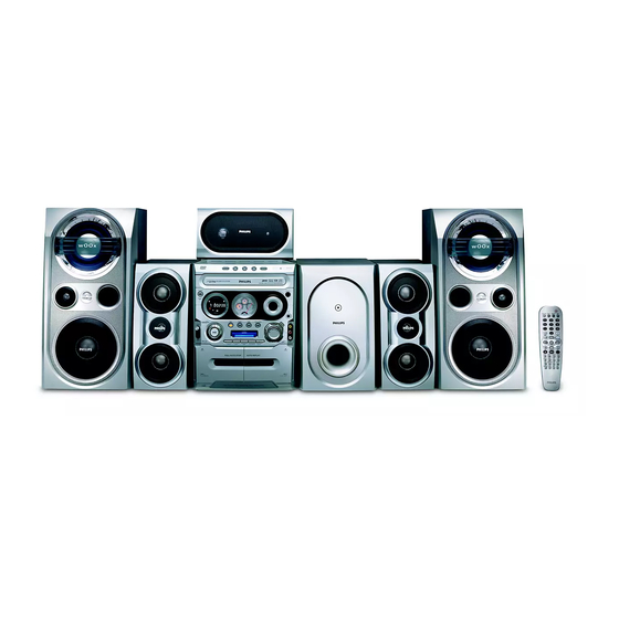
Philips FWD796 Service Manual
Hide thumbs
Also See for FWD796:
- Service manual (67 pages) ,
- User manual (49 pages) ,
- Quick use manual (2 pages)
Table of Contents
Advertisement
Quick Links
Mini System
Service
Service
Service
Service
Service
Service Manual
©
Copyright 2005 Philips Consumer Electronics B.V. Eindhoven, The Netherlands
All rights reserved. No part of this publication may be reproduced, stored in a retrieval system or
transmitted, in any form or by any means, electronic, mechanical, photocopying, or otherwise
without the prior permission of Philips.
Published by SL-ET0519 Service Audio Printed in The Netherlands Subject to modification.
Version 1.0
TABLE OF CONTENTS
Location of PCBs & Specifications .................. 1-2 to 1-3
Measurement Setup & Service Aids ................ 1-4 to 1-5
ESD & Safety Instruction ............................................ 1-6
Lead-Free Information & Service Instruction ............. 1-7
Preparations & Controls & Troubleshooting .. 1-8 to 1-14
Setting Procedure & Repair Instructions ....................... 2
Disassembly Instructions & Service positions .............. 3
Set Block & Wiring Diagram .......................................... 4
Key/Video/Sensor/Phone/Vol /Vu Board ....................... 5
Tuner Board ................................................................... 6
Main Board .................................................................... 7
Power Board .................................................................. 8
Mechanical Exploded View & Parts List ........................ . .9
Subwoofer Part ............................................................ 10
Location of PCBs & Specifications .......................... 10-1
Measurement Setup & Service Position ..... 10-2 to 10-3
Disassembly Instructions & Service Positions ........ 10-4
Set Block & Wiring Diagram ........................ 10-5 to 10-6
Main Board ................................................ 10-7 to 10-11
Power & LED Board ................................ 10-12 to 10-15
Exploded View & Parts List ..................... 10-16 to 10-17
FWD796/
Page
VIDEO CD
CLASS 1
LASER PRODUCT
GB
3141 785 30360
21/21M
Advertisement
Table of Contents

Summary of Contents for Philips FWD796
- Page 1 LASER PRODUCT © Copyright 2005 Philips Consumer Electronics B.V. Eindhoven, The Netherlands All rights reserved. No part of this publication may be reproduced, stored in a retrieval system or transmitted, in any form or by any means, electronic, mechanical, photocopying, or otherwise without the prior permission of Philips.
- Page 2 SET BLOCK DIAGRAM...
-
Page 3: Circuit Diagram - Key Board
CIRCUIT DIAGRAM - KEY BOARD C1805 R284 SW803 C2001 R285 SW804 C2002 R286 TA251 C2003 R287 TA253 C2004 R288 TA255 C2005 R289 TA258 C2006 R291 TA259 C2007 R292 TA260 C2008 R293 TA261 C2009 R294 TA262 C2010 R295 TA263 C2012 R296 TA265 C2013 R297... -
Page 4: Tuner Adjustment Table
TUNER ADJUSTMENT TABLE ANT001 R001 R002 R003 R004 C002 R005 C004 R006 C005 R007 C006 R008 C007 R009 C008 R010 C009 R011 C010 R012 C011 R013 C012 R014 C013 R015 C014 R016 C015 R017 C016 R018 C017 R019 C018 R020 C019 R021 C020... - Page 5 BLOCK DIAGRAM - MAIN BOARD DVD/CD Motor Motor Driver Video ES6603S T V Display RF Amp 8/16-MB Audio DAC Speakers DRAM Audio ADC ES6698 Microphone In Vibratto-II EEPROM S/PDIF A/V Receiver ROM/Flash VFD Panel VFD Driver IR Remote...
-
Page 6: Circuit Diagram - Main Board
CIRCUIT DIAGRAM - MAIN BOARD C294 R235 C2273 R2205 C295 C2266 R236 R2206 SERVO PART C296 R237 C2274 R2208 C297 R238 C2275 R2209 C801 R240 C2276 R2210 C802 C2277 R241 R2211 C803 R242 C2278 R2212 C804 R243 C2279 R2213 C805 C2280 R244 R2214... - Page 7 CIRCUIT DIAGRAM - MAIN BOARD...
-
Page 8: Circuit Diagram - Tape Part
CIRCUIT DIAGRAM - TAPE PART C701 D701 R726 R7001 C702 D702 R727 R7004 C703 D703 R728 R7005 C704 D704 R729 R7007 C705 D705 R730 R7008 C706 D706 R731 R7009 C707 D707 R732 R7010 C708 D708 R733 R7011 C709 D709 R734 R7012 C710 D710... -
Page 9: Circuit Diagram - Power Board
CIRCUIT DIAGRAM - POWER BOARD BD901 A1 C908 A2 C919 D1 C953 A4 C963 B5 C978 D4 C988 A3 C998 CN903 A1 D908 D960 IC954 B4 L959 Q954 R903 R914 R951 R961 R973 R983 R993 TR902 BF901 A2 C909 A2 C920 C1 C954 A4 C964 C5... - Page 10 10-7 10-7 TDA8920TH INTERNAL IC DIAGRAM VDDP2 VDDP1 STAB1 PROT VDDA2 VDDA1 BOOT1 RELEASE IN1- DRIVER INPUT MODULATOR SWITCH1 CONTROL HIGH STAGE IN1+ OUT1 ENABLE1 HANDSHAKE DRIVER MUTE SUBWOOFER MAIN BOARD SGND1 STAB1 VSSP1 OSDILLATOR TDA8920TH TEMPERATURE SENSOR MANAGER VDDP2 CURRENT PROTECTION MODE MODE...
- Page 11 10-8 10-8 CIRCUIT DIAGRAM - MAIN BOARD C302 D6 C576 R409 C2 C303 D7 C577 R410 C2 C401 C2 C578 R411 B2 C403 B2 C579 R412 A2 C404 A2 C580 R413 C3 C405 C2 C901 R414 C3 C406 B2 C902 R415 B3 CN904 C407 B2...
- Page 12 10-12 10-12 IC-KA7500C INTERNAL IC DIAGRAM POWER + LED BOARDS IC-BA4558D INTERNAL IC DIAGRAM TABLE OF CONTENTS Internal IC Diagram ............. 10-12 Circuit Diagram ............10-13 PCB Layout View ............10-14 Electrical Parts list ............10-15 OUTPUT -INPUT +INPUT...
- Page 13 10-13 10-13 CIRCUIT DIRGRAM - POWER BOARD NTC901C1 BD901 D1 Q901 C901 C902 Q902 Q911 C903 L-45UH-8A Q912 C904 C955 470P-1KV L952 C104P-100V Q951 C907 RB951 Q952 D972 C908 UF3003 +27V T901 Q957 1000U 35V C909 D971 UF3003 Q958 C910 C956 -27V C911...


Need help?
Do you have a question about the FWD796 and is the answer not in the manual?
Questions and answers