Table of Contents
Advertisement
Quick Links
Advertisement
Chapters
Table of Contents

Subscribe to Our Youtube Channel
Related Manuals for Daikin brp069a42


Summary of Contents for Daikin brp069a42
-
Page 1: Technical Data
Air Conditioners Technical Data C o n t r o l S y s t e m s E E D E N 1 5 - 1 0 0... -
Page 2: Table Of Contents
Standard protocol interfaces Modbus interface KNX Interface BACNET Interface LonWorks Interface Remote monitoring and maintenance I-Net Daikin configurator software EKPCCAB3 Sensors and other devices Wireless room temperature sensor Wired room temperature sensor Other intergration devices Benefits overview Benefits overview Split... -
Page 3: Survey Control Systems
(2) BRC073 Simplified remote control (with operation mode selector button) BRC2E52C Simplified remote control (without operation mode selector button) BRC3E52C Online controller BRP069A41 Online controller BRP069A42 Online controller BRP069A43 Online controller BRP069A44 Centralised remote control DCS302C51 Unified ON/OFF DCS301B51... - Page 4 • Survey of control systems Split indoor units FTX-J3 FTX-GV FTX20-35K FTX50-60K FVXG-K FVXS-F FDXS-F(9) FLXS-B(9) FTXLS-K FTXL-JV ATXS20-25K ATXS35-50K ATX-J3 ATX-K ATXL-JV x (1) x (1) x (2) x (2) x (2) x (2) x (2) x (2) x (2) x (2) x (2) x (2)
-
Page 5: Individual Control Systems
• Individual control systems • BRC1E52A/B User friendly remote control with contemporary design BRC1E52A/B A series of energy saving functions Other functions that can be individually selected › Up to 3 independent schedules can be set, › Temperature range limit so the user can easily change the schedule himself ›... - Page 6 • Individual control systems • ARC*/BRC* BRC1D52 BRC44B2 ARC466A1 BRC4*/BRC7* BRC944B2*/BRC1D52 ARC4*/BRC4*/BRC7* Wired remote control Infrared remote control › Schedule timer: Operation buttons: ON / OFF, timer mode start / stop, timer mode on / off , programme time, temperature setting, air fl ow direction (1), Five day actions can be set as follows: operating mode, fan speed control, fi lter sign reset (2), inspection set point: unit is switched ON and normal...
- Page 7 • Individual control systems • ARC*/BRC* Specifications Technical Specifications BRC1E52A* / BRC1E52B* Casing Colour Fresh White Button cover Operation LED Colour Green Unit HeightxWidthxDepth 120x120x19 Dimensions Packed unit HeightxWidthxDepth 150x160x55 Weight Unit 0.200 Packed unit 0.415 Material Carton Packing Weight 0.050 Type Full dot (160 x 255)
- Page 8 • Individual control systems • ARC*/BRC* BRC1E52A/B - Wired remote control Dimensional drawing BRC1E52A7 BRC1E52B7 Upper case Lower case • remote control dimensions Operation lamp (green) Code outlet hole 5x15 oblong hole 5x7 oblong hole • Installation method Condit A) Exposed Cord B) Embedded Cord C) Embedded Cord ( Use Switch Box ) Upper center...
- Page 9 • Individual control systems • ARC*/BRC* BRC1D52 - Wired remote control Dimensional drawing (Unit: mm) 5 x 10 (Round end slit) 6.5 x 9 (Round end slit) 5 x 7 (Round end slit) Hole Ø5 Cover closed Cover open 3TW23651-2 BRC4C61,62,65 - Infrared remote control Dimensional drawing (Unit: mm)
- Page 10 • Individual control systems • ARC*/BRC* BRC7E530W - Infrared remote control Dimensional drawing (Unit: mm) Receiver installation procedure Remote control dimensions Transmitting part Drain piping side Refrigerant piping side Receiver Remote control holder installation procedure (installation to wall surface) Decoration panel Liquid crystal (BYFQ60BW1) remote control (BYFQ60B7W1) (wireless) (BYFQ60B8W1)
- Page 11 • Individual control systems • ARC*/BRC* BRC7E618 - Infrared remote control Dimensional drawing (Unit: mm) Remote control dimensions Transmitting part • Receiver installation procedure Receiver 17.5 • Receiver detail Remote control holder installation procedure (installation to wall surface) Liquid crystal remote control (wireless) Remote control holder •...
- Page 12 • Individual control systems • ARC*/BRC* BRC2E52A/ BRC3E52A - Simplified remote control for hotel applications Dimensional drawing (Unit: mm) Upper case Lower case • Remote control dimensions Operation lamp (green) Code outlet hole oblong hole oblong hole • Installation method Condit Exposed cord Staple...
-
Page 13: Brc073
• Individual control systems • BRC073 Purpose Overview of compatible Daikin units ranges System layout 3.1 Typical layout for indoor models with standard S21 connector integrated 3.2 Typical layout for indoor models without S21 connector Specifications 4.1 Technical specifications 4.2 Available documentation 4.3 Outlook and dimensions... -
Page 14: Purpose
• Individual control systems • BRC073 1. Purpose The wired user interface BRC073A1 allows the end user to control connected Daikin indoor units. The wired user interface uses typically the S21 connection of the indoor unit to communicate. 2. Overview of compatible Daikin units ranges Attention: Some indoor models do not have the S21 connector as standard. -
Page 15: System Layout
• Individual control systems • BRC073 3. System layout 3.1 Typical layout for indoor models with standard S21 connector integrated. Required wireharness option available Adapter in different lengths (BRCW901A03/08) BRC073A1 indoor BRC073A 3.2 Typical layout for indoor models without S21 connector Adapter KRP980* Required wireharness option available... -
Page 16: Specifications
• Individual control systems • BRC073 4. Specifications 4.1 Technical specifications BRC073A1 Content 1. User interface 2. wireharness S21 (to be installed between indoor unit and adapter. Length 1 meter.) 3. Adapter 4. Screws + plugs 5. Screws 6. Clamps 7. - Page 17 - BRC073A1 wired user interface is connected to the S21 connector of the indoor unit. - Only one S21 option can be applied at the same time on an indoor units with S21. (Not possible to combine with different other S21 options e.g. BRP069A42 WLAN adapter …) Exception: Due to the fact that the BRC073A1 has been designed to be able to install in combination with KRP928*.
-
Page 18: Available Documentation
For detailed instructions on how to connect the wireharness to the S21 connector for the different indoor units: Refer to the available installation videos for each daikin unit range with similar S21 wireharness installation of Daikin online controller are available on http://www.daikineurope.com/support-and-manuals/product-information. -
Page 19: Outlook And Dimensions
• Individual control systems • BRC073 4.3 Outlook and dimensions 4.3.1 outlook BRC073A1 wired user interface BRC073A1 adapter 4.3.2 dimensions BRC073A1 user interface (mm) Upper case Lower case • Remote control dimensions Operation lamp (green) Code outlet hole 5x15 Oblong hole 5x7 Oblong hole BRC073A1 adapter (mm) •... -
Page 20: Installation Method
• Individual control systems • BRC073 4.4 Installation method 4.4.1 User interface Dimensions in mm • Installation method Exposed cord Staple Embedded cord Upper outlet Note 2 Through hole Left outlet Lower case portion (Remark: Compared with similar BRC*E* casing designs, the upper center outlet installation method is not possible because the hole is to small to install the BRCW901A* wire harness) Condit Embedded cord (use switch box) -
Page 21: Summary Of Features
• Individual control systems • BRC073 5. Summary of features Information: - Only one user interface can be connected to each indoor unit - Avoid using the wired userinterface and the wireless user interface at the same time. When combining usage refer to the user reference guide for the phenomena that can occur. -
Page 22: Clock Function
• Individual control systems • BRC073 Button lock function - activation / de-activation by pushing 4 sec on menu button pushing a non-operable button: message “key are locked” and explenation how to unlock is shown. Typical application: child lock Basic Screen: Standard display With icons (default) With icons and text... -
Page 23: Energy Saving Features (Menu Always Available)
• Individual control systems • BRC073 5.5. Energy Saving features (menu always available) - Setpoint range limitation: The setting temperature range can be restricted. Seperate range limitation in cooling mode, heating mode and auto C/H mode - The setback feature will maintain the space temperature in a specific range during unoccupied periods. Setback temperature range cooling 33°... -
Page 24: Combination Brc073A1 & Krp928* To Connect To Diii Central Control Equipment
• Individual control systems • BRC073 6. Combination BRC073A1 & KRP928* to connect to DIII central control equipment - Refer to the KRP928 adapter manuals for more information concerning the installation and operation. Note 1: To use KRP928, it is required to use a DIII Central device that supplies power on F1/F2 (e.g. ITM) It does not work with devices that do not supply power on F1/F2 (e.g. -
Page 25: Overview Of Compatible Daikin Models
• Individual control systems • BRC073 7. Overview of compatible Daikin models Attention: Some indoor models does not have the S21 connector as standard. In this case, it is needed to install an option adapter with integrated S21 connector. description... - Page 26 • Individual control systems • BRC073 description Brand model range Supported models Wall mounted Wall mounted Daikin FTX-GV FTX20GV1B (KRP980B1 required) FTX25GV1B (KRP980B1 required) FTX35GV1B (KRP980B1 required) FTX50GV1B FTX60GV1B FTX71GV1B Wall mounted Daikin FTXL-JV FTXL25J2V1B (KRP980B1 required) FTXL35J2V1B (KRP980B1 required)
-
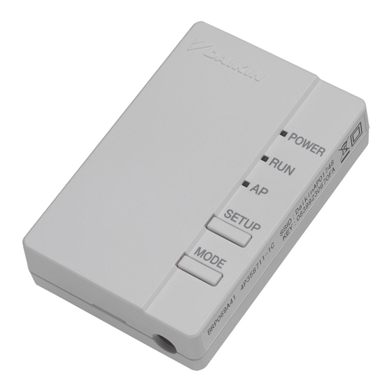
Page 27: Online Controller
› Schedule the set temperature and operation mode with up to 4 actions per day for 7 days Features Online Controller The Daikin online controller can manage your unit in several ways. You can operate it in-home by connecting your... - Page 28 • Individual control systems • Online controller • BRP069A41/42/43/44 WLAN adapter BRP069 combination table / feature list Product name group FTXG FTXJ FTXZ-N FTXS FTXM FTXS FTXLS FTXM FTXS ATXS ATXS Optimized Remark heating Connection between wifi adaptor & indoor unit : ...
- Page 29 • Individual control systems • Online controller • BRP069A41/42/43/44 WLAN adapter BRP069 combination table / feature list Product name group FTX-J FTXL-J FTX-K FTX-G FTX-G FTX-K ATX-J ATX-K ATXL-J FVXG FVXS FLXS-B(9) Optimized Optimized Optimized Remark heating technology technology technology heating heating Connection between wifi adaptor &...
-
Page 30: Centralised Control Systems
• Centralised control systems • Centralised remote control/Unifi ed ON/OFF / Schedule timer Centralised control of the Sky Air and VRV system can be achieved via 3 user friendly compact. These controls may be used independently or in combination with 1 group = several (up to 16) indoor units in combination and 1 zone = several groups in combination. A centralised remote control is ideal for use in tenanted commercial buildings subject to random occupation, enabling indoor units to be classifi ed in groups per tenant (zoning). - Page 31 • Centralised control systems • Centralised remote control/Unified ON/OFF / Schedule timer DCS302C51 - Centralised remote control Dimensional drawing (Unit: mm) Switch box Ø 5 hole Door closed Door open 3D004872 DCS301B51 - Unified on/off control Dimensional drawing (Unit: mm) Optional switch box 2 - 5 x 7 Round end slit 3D004872...
- Page 32 • Centralised control systems • Centralised remote control/Unified ON/OFF / Schedule timer DST301B51 - Schedule timer Dimensional drawing (Unit: mm) Optional switch box 2 - 5 x 7 Round end slit Door closed Door open 3D049544 • Control systems...
- Page 33 Survey of various control systems For more effective localized environmental control Daikin offers various control systems such as single or double remote control or centralized control. This enables the construction of a variety of operational control systems which can be adapted for various uses from remote control to building automation (BA).
- Page 34 • Centralised control systems • wiring details Wiring example of centralised control systems Be sure to connect the wiring of the central controller to (A) or (B). • (Connect to (B), if it is possible.) • Be sure to limit the number of indoor units within the limitation for each system. •...
- Page 35 • Centralised control systems • wiring details Wiring example of centralised control systems • The longest wiring extension should not exceed 1,000 m. (Total wiring length schould not exceed 2,000 m, excluding the wiring to the remote control ). • Up to 128 indoor units can be controlled. Control wiring between induur unit and outdoor unit Outdoor unit...
- Page 36 • Centralised control systems • wiring details Length of transmission wiring The super wiring system, that integrates the control wiring between indoor unit and outdoor unit and the transmission wiring to the central controllers into one common wiring, should satisfy the following limitation. •...
- Page 37 • Centralised control systems • wiring details Length of transmission wiring System example (1) • Branch line; line that is diverged from the main line. • Sub-branch line: line that is diverged from the branch line. • When the centralised remote control is connected to the control wiring between the outdoor units. Line: Main line Line: Branch line The terminal for Out/Out...
- Page 38 • Centralised control systems • wiring details Length of transmission wiring System example (2) • Branch line; line that is diverged from the main line. • Sub-branch line: line that is diverged from the branch line. • When the centralised remote controls are connected to the control wiring between the outdoor unit and indoor unit. Line: Main line Line: Branch line The terminal for Out/Out...
- Page 39 • Centralised control systems • wiring details Length of transmission wiring Number of connectable Units Central control equipment Indoor unit Outdoor unit Other adapters • • • • Target controller (max. number) Centralised remote VRV system Outdoor unit for VRV system External control adapter •...
- Page 40 • Centralised control systems • wiring details Length of transmission wiring Flow chart to determine the number of units to be connected Check sheet for number of units in one system Centralised controller ≤ 1 No. of IPU of intelligent Manager ≤ 2 Intelligent Touch Controller (Note 2) x 10 ≤ 2 x 10 Central remote control (Note 2) ≤...
-
Page 41: Adapter Dta113B51
Monitoring functions via GSM Start/stop, operation mode (fan/cool/heat), temperature setting, error code Malfunction monitoring functions Malfunction reporting function Automatic alternating operation functions via GSM Back-up operation functions via GSM Daikin recommends the use of a Wavecom Fastrack modem • Control systems... - Page 42 • Centralised control systems • DTA113B51 Electric wiring The contact is constant contact. The output conditions are level reading. • When the forced operation contact is closed, all stopped units are continuously instructed to operate. • When the forced stop contact is closed, all operating units are continuously instructed to stop. •...
- Page 43 • Centralised control systems • DCS601C51 • DCS601C51 Detailed & easy monitoring and operation of VRV systems (max. 64 indoor units groups). third party controller (domotics, BMS, etc.) Fire alarm Public line Onboard Ethernet modem Forced OFF contact input Air conditioning Network Service System DIII-NET...
- Page 44 • Centralised control systems • DCS601C51 • Features Web Application & Internet • Control systems...
-
Page 45: System Overview
• Centralised control systems • DCS601C51 • System overview This intelligent Touch Controller is capable of controlling/monitoring up to 64 groups of indoor units (hereafter “groups”). The main functions of the intelligent Touch Controller include: 1 Set back function, enabling a building’s temperature to be monitored and managed during both heating and cooling seasons through a single setting. - Page 46 • Centralised control systems • DCS601C51 • Part Names - Connection Back Terminal block for power supply Modem connector for Air Conditioning Network Service Connect to AC100-240V power supply. RS232-C connector for DIII-NET system Terminal size is M4. Plus adapter When using Air Conditioning Using DIII-NET Plus adapter being Network Service System service, sold as an accessory, you can connect it to the telephone line.
- Page 47 IEC60730 (including IEC60335) Interference (EMC) EN55022 Class A, EN55024 EN55022 Class A, EN55024 Project data & Engineering Configuration and engineering for each project are necessary. For further details, please consult with Daikin distributors and dealers Accessories Description Reference Comments Software...
- Page 48 • Centralised control systems • DCS601C51 • Accessories DEC101A51 - Digital input Dimensional drawing Mounting hole (*) Notes Power supply specifications 1~200-240V 50/60Hz Installation place (198) Rated power consumption • Install the unit indoors where it is not Spare hole (*) exposed to water and dust or dirt.
- Page 49 • Centralised control systems • DCS601C51 • Accessories DEC102A51 - Digital input / output Dimensional drawing Mounting hole (*) (198) Notes Spare hole (*) Power supply specifications 1~200-240V 50/60Hz Installation place Rated power consumption • Install the unit indoors where it is not exposed to water and dust or dirt.
- Page 50 • Centralised control systems • DCS601C51 • Accessories DEC102A51 - Digital input / output External connection diagram DEC102A51 Fuse (10A) switch F1, F2 No. ❈ Wiring procedure Power Supply (1 ~ 200-240V) <F1/F2> wiring between this equipment and centralized control equipment is required. DEC102A51 The connection to the facility equipment and setting of various switches are required.
- Page 51 • Centralised control systems • DCS601C51 • Dimensions System wiring Connecting Unification adaptor allows using the contact for normal and abnormal operation signal and collective start/stop with a contact. For details, contact the vendor you purchased the product from. Also, by connecting DIII-NET-plus adapter, it is possible to operate and monitor the indoor units of 64 groups (intelligent Touch Controller plus DIII-NET –...
- Page 52 Electric power meter (with pulse output) Power proportional distribution pulse. Maximum number of inputs -3 DIII-NETx1 Outdoor unit DCS601C51 PCMCIA card slot Indoor unit DCS002A51 DAIKIN INDUSTRIES. LTD. 64 units at maximum Bills may be issued by use of a general Power Proportional purpose table calculation software package in Distribution Card easy manners. General Bills purpose software A personal computer and a general purpose table calculation software package may be available separately.
- Page 53 • Centralised control systems • DCS601C51 • Power Proportional Distribution Card File Format When Power Proportional Distribution Report is saved, a zone information file, an electric power information file and detailed information file are created. Zone information file This contains zone name and information of air conditioners in the zone. (1) File name : ZONE.CSV (2) File format: (Example)
-
Page 54: Mini Building Management System
• Management control • TABLE OF CONTENTS System overview and main features Functions & options 2.1. Functions 2.2. Options Specifications 3.1. Intelligent Touch Manager 3.1.1. Main specifications 3.1.2. Location of terminals and switches 3.1.3. Required space 3.1.4. Connections 3.2. iTM plus adaptor 3.2.1. -
Page 55: System Overview And Main Features
• Management control • DCM601A51 • DCM601A51 Mini BMS • Price competitive mini BMS • Cross-pillar integration of Daikin products • Integration of third party equipment with full integration across all product pillars System overview Web Access Internet Extranet http interface... - Page 56 › Operational history schedule, yearly calender, - Fan coils › Spanish (malfunctions, operation hours, …) seasonal schedule) - Daikin Altherma Flex type › Dutch › Smart energy management › Interlock control - LT and HT hydroboxes › Portuguese - monitor if energy use is ›...
-
Page 57: Functions & Options
• Management control • DCM601A51 • 2. Functions & Options 2.1. Functions Category Function Remarks iTM plus adaptor (DCM601A52) Maximum number of adaptors: 7 Maximum number of management points: 650 Management points (Number of DIII connection management points: 512) Maximum number of areas: 650 Areas Maximum area hierarchies: 10 Supported languages English, French, German, Italian, Spanish, Portuguese, Dutch, Chinese, and Japanese Basic functions Icon view Icons show the operation status of equipment. -
Page 58: Options
• Management control • DCM601A51 • Category Function Remarks intelligent Touch Manager (DCM601A51) Maximum number of units: 5 Maximum number of management points: 3.250 Management points (Number of DIII connection management points: 2.560) Basic functions Maximum number of areas: 3.250 Areas Maximum area hierarchies: 10 English, French, German, Italian, Spanish, Portuguese, Dutch, Chinese, and Supported languages Japanese 2.2. Options ■ Types of management points and target equipment/interface Management point Supported equipment Number of management points... - Page 59 • Management control • DCM601A51 • ■ DAIKIN supplied equipment ■ Locally supplied equipment Model Item Model Item DCM601A51 intelligent Touch Manager USB 2.0 USB memory Up to 32GB memory can use DCM601A52 iTM plus adapter (Option) Windows XP Professional SP3 (32bit) DCM601A53 iTM integrator (Option)
-
Page 60: Specifications
• intelligent Touch Manager • ED721208 3. Specifications 3.1. Intelligent Touch Manager 3.1.1. Main specifications POWER SUPPLY: DCM601A51 AC100-240V(± 10%)(50/60Hz) Port Number INPUT: 23W MASS: 2.4kg D III D III-NET (Up to 64 groups) FUSE AMP: 3.15A Operating temperature limit: -0°C - +40°C Web Access (100BASE-TX) Operating humidity limit: MAX. -
Page 61: Location Of Terminals And Switches
B [DIII] The communication line connection terminals for “DIII-NET”, which enables communications with DAIKIN’s air conditioning equipment. C [LINE, PHONE] The sockets used when subscribing to the DAIKIN “Air Conditioning Network Service System” online monitoring service for air-conditioning systems. To use the “Air Conditioning Network Service System” service, you need to sign a separate maintenance contact. - Page 62 • intelligent Touch Manager • ED721208 Front panel Located below the monitor display on the front panel are four LEDs that indicate the operating status of the intelligent Touch Manager. Sliding the front slide cover down and then removing a screwed cover reveals terminals used during the setup after installation or during maintenance work.
- Page 63 • intelligent Touch Manager • ED721208 Side face On the left side face of the intelligent Touch Manager, a USB port cover is provided. You use this cover during setup after installation or during maintenance. You also see an attached label, bearing the model, weight, power ratings and the serial number of the intelligent Touch Manager.
-
Page 64: Required Space
• intelligent Touch Manager • ED721208 3.1.3. Required space To install the intelligent Touch Manager, the following space is required. Make sure that there is a minimum clearance of 30 mm from the top edge, 100 mm from the left side edge, 30 mm from the right side edge, and 60 mm from the bottom edge of the unit. <Installation space required for intelligent Touch Manager>... -
Page 65: Connections
• intelligent Touch Manager • ED721208 3.1.4. Connections To connect the DIII-NET communication line, use the 2 terminals F1 and F2 under the label “DIII” on the rear face. These 2 terminals have no polarity. An example of connecting more than two air conditioning devices is shown in the following conceptual connection diagram. CAUTION Make sure that the wires you are connecting to the F1 and F2 terminals are not power wires. - Page 66 Precautions for using multiple centralized controllers Equipment that controls multiple air conditioners is referred to as “centralized controller”. DAIKIN’s product portfolio includes a wide range of centralized controllers suited to different applications or target sizes, which can be used in combination to construct an optimal air conditioning control system.
- Page 67 • intelligent Touch Manager • ED721208 <DIII MASTER> To set the intelligent Touch Manager to SLAVE, use the DIII MASTER switch located under the front slide cover. Placing the SLAVE DIII MASTER switch in the upper position (labeled as “SLAVE”) changes it to a SLAVE.
- Page 68 • intelligent Touch Manager • ED721208 Terminals location and conceptual connection diagram Using a LAN cable, connect the LAN socket to the network hub. <Conceptual drawing of LAN connection> A Rear face of intelligent Touch Manager B LAN cable C Hub D PC Requirements that must be met •...
- Page 69 Connecting I/O module The intelligent Touch Manager can be used in conjunction with the I/O module. The I/O module provides a maximum of 960 I/O points for controlling non-DAIKIN peripheral equipment such as lighting equipment and security lock systems. WARNING •...
- Page 70 • intelligent Touch Manager • ED721208 Connecting an emergency stop input device or electric energy meters The intelligent Touch Manager can be connected with an external signal input device for stopping air conditioners in an emergency, or with electric energy meters for calculating the electricity usage of individual air conditioners (when power distribution is enabled). WARNING •...
- Page 71 • intelligent Touch Manager • ED721208 Terminals location and conceptual connection diagram Connect the contact input lines or pulse signal lines to the Di1, Di2, Di3, Di4, and COM terminals of the orange connector located on the rear face. Each terminal has a different function. [Di1] Emergency stop input [Di2] [Di3] [Di4] Pulse input, contact signal input [COM] Common...
-
Page 72: Itm Plus Adaptor
• intelligent Touch Manager • ED721208 3.2. iTM plus adaptor 3.2.1. Main specifications POWER SUPPLY: DCM601A52 AC100-240V(± 10%)(50/60Hz) Port Number INPUT: 6W MASS: 0.5kg plus ADP IF iTM plus adaptor (Up to 7 adaptors) FUSE AMP: 3.15A Operating temperature limit: -10°C - +50°C D III D III-NET (Up to 64 groups) Operating humidity limit: MAX. -
Page 73: Dimensions
• intelligent Touch Manager • ED721208 3.2.1.1 Dimensions iTM plus adaptor body 160mm 140mm 61.2mm 6.5mm 6.5mm 61.2mm 3.2.2 Location of terminals and switches Understand the arrangement of terminals and switches on the unit and draw up an efficient work plan. For connection details including the cable type, terminal size, and wiring precautions, refer to “2. - Page 74 <Front face of iTM plus adaptor> A [plus ADP IF] The terminals for connecting an intelligent Touch Manager or iTM plus adaptor installed in parallel. B [DIII] The communication line connection terminals for “DIII-NET”, which enables communications with DAIKIN’s air conditioning equipment.
- Page 75 • intelligent Touch Manager • ED721208 The table below shows the status of the CPU ALIVE/ALARM LED when the iTM plus adaptor is operating normally or failed. NOTE [LED status and operation table] Operating condition CPU ALIVE ALARM Normal Blink Hardware failure Address failure plus ADP IF communication failure...
-
Page 76: Connections
• intelligent Touch Manager • ED721208 3.2.3. Connections If you have many air conditioners, use iTM plus adaptors to connect them. It is a fact that the number of indoor groups you can control using a single intelligent Touch Manager is limited to 64. By using iTM plus adaptors, however, you can connect additional 64 groups of indoor units per iTM plus adaptor. - Page 77 • intelligent Touch Manager • ED721208 Connecting intelligent Touch Manager The iTM plus adaptor is a device that enables you to control more air conditioners with the intelligent Touch Manager. It needs to be connected to an intelligent Touch Manager to provide this capability. Terminals location and conceptual connection diagram Connect the terminals located in the “plus ADP IF”...
- Page 78 • intelligent Touch Manager • ED721208 Terminals location and conceptual connection diagram To connect the DIII-NET communication line, use the two terminals F1 and F2 under the label “DIII”. These 2 terminals have no polarity. An example of connecting more than 2 air conditioning devices is shown in the following conceptual connection diagram. CAUTION Make sure that the wires you are connecting to the F1 and F2 terminals are not power wires.
- Page 79 Precautions for using multiple centralized controllers Equipment that controls multiple air conditioners is referred to as “centralized controller”. DAIKIN’s product portfolio includes a wide range of centralized controllers suited to different applications or target sizes, which can be used in combination to construct an optimal air conditioning system.
- Page 80 • intelligent Touch Manager • ED721208 <DIII MASTER> To set the iTM plus adaptor to SLAVE, use the DIII MASTER switch. Placing the switch in the upper position (labeled as “SLAVE”) changes it to a SLAVE. SLAVE MASTER To install multiple centralized controllers, set only the highest priority controller to MASTER and all other controllers to SLAVE according to the following order of priority: (1) Interface for use in BACnet High...
- Page 81 • intelligent Touch Manager • ED721208 Terminals location and conceptual connection diagram Use the terminals located under the label “Di” to connect the pulse signal line. The iTM plus adaptor accepts four types of signals through its four channel terminals, Di1, Di2, Di3, and Di4, and two COM terminals (ground). <Conceptual drawing of Di connection>...
-
Page 82: Itm Integrator
• intelligent Touch Manager • ED721208 3.3. iTM Integrator 3.3.1. Main specifications • iTM integrator body 256.6mm 272mm 25mm 25mm 4.5mm 4.5mm 4.5mm 4.5mm 290mm • Wall mounting metal plate 234.2mm 60mm 40mm Thickness 0.8mm • Control systems... -
Page 83: Location Of Terminals And Switches
• intelligent Touch Manager • ED721208 3.3.2. Locations of terminals and switches Understand the arrangement of terminals and the location of openings on the unit and plan how to route the cable and in which order to connect its wires to facilitate the installation procedure. For connection details including the cable type and terminal size, refer to “2. Connection”. - Page 84 • intelligent Touch Manager • ED721208 Front panel Located below the monitor display on the front panel are four LEDs that indicate the operating status of the iTM integrator. Sliding the front slide cover down and then removing a screwed cover reveals terminals used during the setup after installation or during maintenance work.
- Page 85 • intelligent Touch Manager • ED721208 Side face On the left side face of the iTM integrator, a USB port cover is provided. You use this cover during setup after installation or during maintenance. You also see an attached label, bearing the model, weight, power ratings and the serial number of the iTM integrator. <Side face of iTM integrator>...
-
Page 86: Required Space
• intelligent Touch Manager • ED721208 3.3.3. Required space To install the iTM integrator, the following space is required. Make sure that there is a minimum clearance of 30 mm from the top edge, 100 mm from the left side edge, 30 mm from the right side edge, and 60 mm from the bottom edge of the unit. <Installation space required for iTM integrator>... -
Page 87: Connections
• intelligent Touch Manager • ED721208 3.3.4. Connections This chapter describes the procedure for connecting the iTM integrator with the intelligent Touch Manager. Required procedures • 2.3 Connecting power supply • 2.2 Connecting a LAN cable WARNING • Do not turn the power supply on until all connections are made. Also, make sure that the local circuit breaker, if available, is turned off. - Page 88 • intelligent Touch Manager • ED721208 Connecting a LAN cable Connecting your iTM integrator with network enables you to operate the intelligent Touch Manager from iTM integrator. One iTM integrator can operate a maximum of 5 intelligent Touch Manager. A iTM integrator B intelligent Touch Manager C Hub D Air conditioners or other devices that the intelligent Touch Manager is monitoring.
- Page 89 • intelligent Touch Manager • ED721208 Terminals location and conceptual connection diagram Using a LAN cable, connect the LAN socket to the network hub. <Conceptual drawing of LAN connection> A Rear face of iTM integrator B LAN cable C Hub D PC E intelligent Touch Manager Requirements that must be met...
-
Page 90: Accessoires
• intelligent Touch Manager • ED721208 4. Accessories 4.1. Di Unit <DEC101A51> Using this unit, connection of other facilities other than air conditioner is made possible, such as power supply facility, sanitary facility, anti-disaster facility, and crime prevention facility. Function Type BRC1C62 DEC101A51... - Page 91 • intelligent Touch Manager • ED721208 Part Names and Functions Appearance Di Unit DEC101A51 PCB in DEC101A51 • Control systems...
- Page 92 • intelligent Touch Manager • ED721208 The figure below shows the printed circuit board built in this equipment. DIII-NET Address No. setting switch (RS1/DS1) Set DIII-NET Address No. Terminal block for transmission (F1/F2) (Terminal size: M3) Connect this unit to the terminals F1, F2 Power supply terminal of the centralized control equipment.
- Page 93 • intelligent Touch Manager • ED721208 Installation (Installation Place) • Install the unit indoors where it is not exposed to water and dust or dirt. • Install the unit where both temperature and humidity do not become high. (Operating (available) temperature: -10 ~ +40°C) (Operating (available) humidity: 10 ~ 85%) • Connect the wiring to be connected in the field from the lower surface side.
- Page 94 • intelligent Touch Manager • ED721208 Restrictions in Continuous Installation In case where several devices are set up and installation inside the power board is carried out, each equipment installation space and space between the wall surface and this equipment should be left at least as shown below. Unit (mm) DEC101A51 DEC101A51 DEC101A51 DEC101A51 Fix the DEC101A51 firmly with the installation screws (M4) (To Remove Front Panel:) “1.5.4 Electric Wiring Work and Initial Setting”...
- Page 95 • intelligent Touch Manager • ED721208 Electric Wiring Work and Initial Setting Electric wiring work Wiring Lead-In For wiring connection, remove the front panel (secured with 2 screws) of this equipment. Upon completion of operation given in this paragraph and “2. Initial Setting” below, close the front panel with the screws described above. ➀ To 1 ~ 200 - 240 V and earth × AC200V ~240V × × ➁ To facility equipment INPUT ×...
- Page 96 • intelligent Touch Manager • ED721208 Initial setting • DEC101A51 Switch Settings Name Operation Abnormal input detection Open/Close Open Close Abnormal input detection method (Concentrated address +4 to 7) Open: Close (Normal) Æ Open (Abnormal) Abnormal input detection Open/Close Close: Open (Normal) Æ Close (Abnormal) Open Close (Concentrated address +0 to 3)
- Page 97 • intelligent Touch Manager • ED721208 * Number of centralized addresses used The number of centralized addresses used is determined by the top address set in this item and the number of facility equipment connected that is set in “➂ TP1 Setting (Facility equipment quantity change)”. Example 1: When the top address was set to “1-00” and the number of facility equipment was set to “2”, it follows that “1-00” and “1-01” are being used. Example 2: When the top address was set to “3-15” and the number of facility equipment was set to “8”, it follows that “3-15”, “4-00”, “4-02”, “4-03”, “4-04”, “4-05” and “4-06” are being used. <CAUTION>...
- Page 98 • intelligent Touch Manager • ED721208 By short-circuiting the quantity change TP1 in the normal operating condition, the setting status can be confirmed. 1 unit 2 units 3 units 4 units Operation monitor 5 units 6 units 7 units 8 units This indicates LED lighting. Electric wiring connection Wiring Procedure ➀...
- Page 99 • intelligent Touch Manager • ED721208 4.2. Dio Unit <DEC102A51> Using this unit, connection of other facilities other than air conditioner is made possible, such as power supply facility, sanitary facility, anti-disaster facility, and crime prevention facility. Function Type BRC1C62 DEC102A51 Group/Zone One Group...
- Page 100 • intelligent Touch Manager • ED721208 Operation output It is possible to select continuous 1 output (4 points) or instantaneous 2 output (ON/OFF pair-2 points). For switching, refer to 2. Initial Setting ➃ • Wiring at Continuous Output (Up to 4 facility equipments can be connected.) Facility Equipment Operation Circuit Example 1~200-240V DEC102A51 REMOTE LOCAL Operation Local command D1~4 stop Local operation...
- Page 101 • intelligent Touch Manager • ED721208 Operation input When the contact is “Closed”, “Run” is to be inputted. Input SPEC: No-voltage “a” contact (When applied voltage is 20 tot 30V DC and the contact is “Closed”, the welding current is approx.
- Page 102 • intelligent Touch Manager • ED721208 Part Names and Functions Appearance Dio Unit DEC102A51 PCB in DEC102A51 • Control systems...
- Page 103 • intelligent Touch Manager • ED721208 The figure below shows the PC board built in this equipment. DIII-NET Address No. setting switch (RS1/DS1) Power supply terminal block Set DIII-NET Adress No. (L, N) For the power supply, use 1 ~ 200 - 240V. Terminal block for transmission (F1/F2) Switch for selecting the number of (Terminal size: M3)
- Page 104 • intelligent Touch Manager • ED721208 Specifications Dio board 8 points. 4 pairs based on a pair of On/Off input and abnormality input Input contacts * Contact information(On/Off, Abnormality ) is transmitted to intelligent Manager III through DIII-Net communication. 4 points. In case of normally output, 4 units are controllable.
- Page 105 • intelligent Touch Manager • ED721208 Installation (Installation Place) • Install the unit indoors where it is not exposed to water and dust or dirt. • Install the unit where both temperature and humidity do not become high. (Operating (available) temperature: -10 ~ +40°C) (Operating (available) humidity: 10 ~ 85%) • Connect the wiring to be connected in the field from the lower surface side.
- Page 106 • intelligent Touch Manager • ED721208 Restrictions in Continuous Installation In case where several devices are set up and installation inside the power board is carried out, each equipment installation space and space between the wall surface and this equipment should be left at least as shown below. DEC102A51 DEC102A51 DEC102A51 DEC102A51 Fix the DEC102A51 firmly with the installation screws (M4) (To Remove front Panel:) “1.4.4 Electric Wiring Work and Initial Setting”...
- Page 107 • intelligent Touch Manager • ED721208 Electric Wiring Work and Initial Setting Electric Wiring Work No simultaneous clamping is allowed for high-voltage wiring <power supply wiring (L/N), earth wiring, relay output wiring (CD, D1 to 4)>, low-voltage wiring <communication wiring (F1/F2), operation input wiring (CM, M1 to 4) and abnormal input wiring (CA, A1 to 4)> since malfunctioning may result. Also, in case where the wirings described above are routed in parallel, be sure to connect the wirings at least AC200V...
- Page 108 • intelligent Touch Manager • ED721208 Factory preset before shipment C/C : Centralized control equipment C/D : Connectable Devices or Facility equipment Switch Condition Factory preset before shipment Range of address No. 1-00, 01, 02, 03 A1 - AM Abnormal in the open condition DS4-1 Power failure, then after power recovery Stop...
-
Page 109: Dio Unit Dec102A51
• intelligent Touch Manager • ED721208 ➀ Set the top address of this equipment with the DIII-NET setting switch (DS1/RS1). Using the DIII-NET setting switch (DS1), set the range of Adress No. that is set in this equipment. Address Nos. 1-00 to 1-15 are factory controlled before shipment. 1-00 ~ 1-15 2-00 ~2-15 3-00 ~ 3-15 4-00 ~ 4-15 Control range DS1 * when a product is discharged from the factory Control range DS1 (high order) setting (Address range) ∗ This indicates the switch knob. - Page 110 • intelligent Touch Manager • ED721208 ➃ DS4-1 Setting This switch selects continuous output or instantaneous output for control outputs (D1 to D4) commanded to the facility equipment. Set to “Con.” side (factory preset before shipment) --- Continuous output (Contacts D1 to D4 at the time of operation command from the centralized control equipment: ON-Contacts D1 to D4 at stop command: OFF) Operation command Stop command Contact D1 ~ D4 Set to “Ins.” side --- Instantaneous output (Contact D1 or D3 at the time of operation command from the centralized control equipment: ON for one second only-Contact D2 or D4 at stop command: ON for one second only) Operation command Contact D1 (1st facility equipment) Contact D3 (2nd facility equipment) Stop command Contact D2 (1st facility equipment) Contact D4 (2nd facility equipment) ➄ TP1 Setting (Facility equipment quantity change) This function is used to set the number of facility equipment controllable with this equipment.
-
Page 111: Power Proportional Distribution
• intelligent Touch Manager • ED721208 5. Power proportional distribution System Architecture Confirmation of Watthour Meter For distribution of electric energy, the integrating watthour meter with pulse transmitter is required. It is important to confirm that the specifications coincide with each other, and also to confirm with the division in charge (normally, electrical work division, not air-conditioning div.). - Page 112 • intelligent Touch Manager • ED721208 Design Precautions Calculation Condition Watthour meter (For VRV outdoor units) Watthour meter (For VRV indoor units) Group 1 DIII-NET Remote controller group control (1) Remote controller group ➀ Also in the indoor unit (sub-unit) with remote controller group, set the group address for correct electric energy distributing. (The group address for sub-unit can be set in the site set mode “30”...
- Page 113 • intelligent Touch Manager • ED721208 Setting of Each Electric Power Group Watthour meters have to be installed for Heat Pump type VRV and Heat Recovery type VRV respectively as shown below figure and make power groups respectively. Watthour meter Watthour meter Group 1 Group 2...
- Page 114 • intelligent Touch Manager • ED721208 The Reason why VRV Heat Recovery must not be Included For Heat Recovery outdoor units, the watthour meter must be independently installed. (1) For heat recovery, there is a case that the power consumption is less than VRV and VRV Plus. (2) However, if different systems are put on the one meter, the electric power distribution would be calculated by constant counting, and the calculation result would then more than the actual value on all indoor units.
- Page 115 • intelligent Touch Manager • ED721208 Explanations of Power Proportional Distribution What is the Power Proportional Distribution (PPD) (System Ex. : Normal VRV) Since this system detects power consumption as the base of billing, specified watthour meters should be used by all means Watthour meter with output Power supply 3 phase Outdoor unit Power supply single phase...
- Page 116 • intelligent Touch Manager • ED721208 2) Counting the electricity at the stopped condition of the unit Even if a VRV is stopped or in the condition of thermostat -OFF (the condition that the compressors are stopped as the temperature in the space where all the indoor units are installed falls down to the set temperature), the VRV consumes energy due to the energy consumption mainly by the crankcase heater in the outdoor unit.
- Page 117 • intelligent Touch Manager • ED721208 Count Accuracy (1) Cause of error (System example) Watthour meter (with output) Power supply 3 phase Outdoor unit Tenant A Tenant B Tenant C Legend : Read on wattmeter #: Indoor unit’s address <Case of arising error> ➊...
- Page 118 • intelligent Touch Manager • ED721208 iTM counts the power consumption as the following conditions (1)~(6) for the standards. So, the gap to be raised from these conditions may cause the error. Since these errors vary depending on the surrounded situations, the worst error value cannot be drawn out from the computing.
- Page 119 • intelligent Touch Manager • ED721208 Notes • It is not possible to apportion power consumption for the VRV series indoor unit FXUQ (ceiling suspended cassette type). (Reason) VRV and Sky Air use different methods to calculate thermo step, which is a parameter necessary for power consumption apportionment. For the VRV, the indoor unit calculates thermo step.
- Page 120 • intelligent Touch Manager • ED721208 Reference Material Case Examples (1) A value on a wattmeter of each outdoor unit system does not correspond to PPD result. Electric power of wattmeter A is nearly the same as that of wattmeters B + C + D. However, the PPD result of outdoor unit system 1 (4 indoor units) does not correspond to the value on wattmeter B.
- Page 121 • intelligent Touch Manager • ED721208 (2) A group address is not set to a slave indoor unit with remote controller group. iTM cannot control slave indoor units (Indoor units B, D, G, and H in the following figure) in remote controller group. In general, the setting of a group address is not required for control with a remote controller group.
- Page 122 • intelligent Touch Manager • ED721208 (3) A PPD calculation result for a certain tenant is excessively large. iTM distributes electric power based on operation data from an indoor unit. If only one VRV indoor unit is in operation, electric power consumed by an outdoor unit increases because a compressor is turned ON only for one indoor unit in operation.
-
Page 123: Diii-Net
What is DIII-NET? DIII-NET is a proprietary high-speed communication method developed by Daikin, with which huge amount of information can be transmit at high speed and various facilities of a building, such as air conditioners, can be freely connected via networks in accordance with the usage, scale, and conditions. - Page 124 • intelligent Touch Manager • ED721208 Connection Method Correct Wiring • Series wiring method only should be used. [Example] Connect indoor units and outdoor units without branch connection. Indoor-outdoor VRV Outdoor unit connection IN/OUT F1 F2 Outdoor-outdoor OUT/OUT connection F1 F2 VRV Indoor unit Connect outdoor units without branch connection.
-
Page 125: Wiring Example
• intelligent Touch Manager • ED721208 Wiring Example Example of Control Wiring • Be sure to connect the wiring of the centralized control equipment to control wiring between outdoor units. When wiring connections are made between indoor and outdoor units, there may be cases where control over normal systems may become impossible if one of the connected systems should happen to fail. - Page 126 • intelligent Touch Manager • ED721208 <Pattern 2> • When all the centralized control equipment is located at one place. Control wiring between indoor unit and outdoor unit Possible ★ Outdoor unit ( 1) ( 1) System 1 It is possible to operate without remote controller.
- Page 127 • intelligent Touch Manager • ED721208 Wiring Length • Total length must be 2000m or less. (The total wiring length is 1500m when shielded wire use.) • Max. length must be 1000m or less. [Example] 200m Outdoor unit Outdoor unit 100m 500m 200m...
- Page 128 1. ★1 ..VRV system, SkyAir series and other air-conditioner. 2. ★2 ..VRV system or other Daikin air-conditioner produces less electrical noise, so that the distance of 50mm or more is sufficient. For control wiring, never use the shield wire together with other sheathed vinyl cord in the same system, which may cause the malfunction in transmission.
- Page 129 • intelligent Touch Manager • ED721208 Unit and Group Indoor Unit and R/C No. of Group No. of Indoor Unit P1·P2 Indoor Unit Indoor Unit P1·P2 P1·P2 P1·P2 Outdoor Unit No. of Outdoor Unit 10HP Refrigerant F1·F2 18HP Refrigerant F1·F2 28HP Refrigerant Q1·Q2...
- Page 130 • intelligent Touch Manager • ED721208 Number of Connectable Units Number of Units to be Connected [VRV] (Supplementary Explanation) • Up to 10 VRV outdoor units can be connected to DIII-NET. - In case of VRVII and VRVIII, an outdoor unit which consists of multiple modules is counted as one unit. Each module is counted as 1 unit 2-unit module...
- Page 131 • intelligent Touch Manager • ED721208 Connection of Devices other than VRV • You can connect adaptors and other devices (Sky Air adapter, Split adapter, Di/Dio units, etc.), which are not VRV, to either indoor- outdoor connection or outdoor-outdoor connection. •...
-
Page 133: Standard Protocol Interfaces
› Modbus interface for monitoring and control of Sky Air, VRV, VAM and VKM › Intelligent hotel room controller RTD-W › Modbus interface for monitoring and control of Daikin Altherma Flex Type, VRV HT hydrobox and small inverter chiller • Control systems... - Page 134 • Standard protocol interfaces • RTD - modbus interface Overview functions Main functions RTD-RA RTD-RA/SMART RTD-NET RTD-10 RTD-20 RTD-HO Dimensions H x W x D 80 x 80 x 37,5 80 x 80 x 37,5 100 x100 x 22 Key card + window contact ...
-
Page 135: Knx Interface
Controller Interface Daikin protocol/ KNX KNX interface line-up The integration of Daikin indoor units through - such as “Home leave” - in which the end-user selects the KNX interface allows monitoring and control a range of commands to be executed simultaneously of several devices, such as lights and shutters, from once the scenario is selected. -
Page 136: Bacnet Interface
• Standard protocol interfaces • BACnet Interface BACnet Interface Integrated control system for seamless connection between VRV, applied systems, air handling units and BMS systems ʯ Interface for BMS system ʯ Communication via BACnet protocol (connection via Ethernet) ʯ Unlimited sitesize VRV network ʯ Easy and fast installation ʯ... - Page 137 Tracer Summit Trend Tridium Niagara Framework 2.301.321.v1 Trilogy (*) Please contact your Daikin distributor for further details or other manufacturers concerning compatibility. Specifications BACnet Interface (DMS502A51) Description Rated Electrical conditions Rated Voltage and Frequency Single Phase AC 200-240, 50/60 Hz...
- Page 138 Dimensions BACnet Interface (DMS502A51) BACnet Interface outside drawing (DMS502A51) 24 - M2.5 4 - M3.5 D-SUB 9Pin (male) D-SUB 9Pin (male) DAIKIN D-BACS Power AC100-240V 50/60Hz 4 - M3.5 4 - M3.5 3 - M3.5 10 - M2.5 3D056945 Option DIII board (DAM411B51) This kit is for adding 2 ports to the DIII-NET communication port by installing it on the BACnet Interface DMS502A51.
- Page 139 • Standard protocol interfaces • BACnet Interface Communications Check Sheet BACnet object list Unit Memner Object name Name Object type Inactive Active number (XXX: Air Con Logical Group Number) Text-1 Text-2 Text-3 Text-4 Start/stop (setting) (Note 2) Start stop command_XXX Stop Operation Start/stop (status)
-
Page 140: Main Functions
This is used when distribution the power supply to indoor This connector for connecting with the central units (No Voltage) monitoring board using RS232C Terminal block for communication with (option model name: DAM412B51) air conditioners (option model name: DAM411B51) (15) (13) DAIKIN D-BACS ETHER ALIVE ALRN LINK Power 68.5 AC100-240V DIII ETHER... - Page 141 • Standard protocol interfaces • BACnet Interface Function Major functions of air-conditioner devices Air-conditioning equipment Interface adapter Wiring adapter Function Remarks VRV Inverter for Sky Air series for other series (SA Heat Pump) air-conditioners Start/stop control and monitoring Air-conditioner error notification Indoor air temperature monitoring Temperature setting and monitoring 0 16~32...
- Page 142 DI (12) F1 F2 F1 F2 F1 F2 maximum of 64 groups ACNSS Telephone line Telephone maintenance Central monitoring board Power supply 100V-240V DAIKIN D-BACS 50/60Hz Ethernet BACnet client Power AC100-240V 50/60Hz DIII-1 DIII-2 RS485 Do-1 Do-2 Earth leakage breaker (install for safety) Outdoor Terminal contact size: M3.5...
- Page 143 • Standard protocol interfaces • BACnet Interface Wiring and Setting Procedures External wiring Everything relating with field wiring must be supplied in the field. Ethernet communication wiring Field supplied DMS502A51 10BASE-T straight cable Ethernet 10BASE-T BACnet client DIII-NET wiring DMS502A51 Outdoor unit Recommended wire size 0.75~1.25mm...
-
Page 144: Lonworks Interface
• Standard protocol interfaces • LonWorks Interface LonWorks Interface Open network integration of VRV and applied systems monitoring and control functions into LonWorks networks LON BMS ʯ Interface for Lon connection to LonWorks networks ʯ Communication via Lon protocol (twisted pair wire) VRV network ʯ Unlimited sitesize ʯ... - Page 145 • Standard protocol interfaces • LonWorks Interface LowWorks Interface for VRV Survey of Functions Function Description ON/OFF Command Starts/stops air conditioner operation. Operation Mode Setting Sets operation mode (heating/cooling/ventilation/auto). Temperature Setting Sets room temperature. Airflow Rate Setting Sets airflow rate. Filter Sign Reset Resets filter sign.
- Page 146 • Standard protocol interfaces • LonWorks Interface Applicable Models Air Conditioners Facility A/C Function Large Sky Air Sky Air (Centralized (General purpose Multi (Adapter for Sky Air) control adapter) adapter) ON/OFF operation and monitoring ▲ ▲ ▲ ▲ ▲ ▲ A/C error report ▲...
- Page 147 • Standard protocol interfaces • LonWorks Interface Dimensional drawing DMS504B51 1681 R2,25 R2,25 49.6 8 - C3 Alive/wink Detailed drawing of fixing hole Service Service switch Notes 1 Rated electrical conditions: Rated voltage and frequency: single phase Caution AC100~240V 50/60Hz Manufacturer's Rated power: Maximu 5W Make sure the power supply is off when carrying out label the following works:...
- Page 148 • Standard protocol interfaces • LonWorks Interface External connection diagram DMS504B51 No. ❈ Wiring specifications LonWorks Network Communication wiring Alive/wink Use the dedicated line for the LonWorks Network Service Service switch DMS504B51 Polarity: No. Caution Make sure the power supply is off when DIII-net wiring carrying out the following works: 4 — M3.5 3 —...
-
Page 149: Remote Monitoring And Maintenance I-Net
Focus on your core business and hand the HVAC service life while reducing the energy bill. over to Daikin. Daikin I-Net connects your system continuously with Daikin. It notifies alarms and early warnings of system deviations to maximise system uptime and the comfort of the people in the building. - Page 150 › Early fault indication (predictions) : operation data › if there is a problem, Daikin specialists will analyse are 24/7 checked by I-Net prediction algorithms the operation data history to provide remote to act as early as possible, averting unscheduled support.
-
Page 151: Daikin Configurator Software
Simplified commissioning graphical interface to configure, commission and upload system settings The Daikin configurator for Daikin Altherma and VRV is an advanced software solution that allows for easy system configuration and commissioning: › Less time is required on the roof configuring the outdoor unit ›... -
Page 152: Sensors And Other Devices
› No need for wiring › No need to drill holes › Ideal for refurbishment Connection diagram Daikin indoor unit PCB (FXSQ-P example) Power supply – X35, X13 Air sensor – X16A, X1 Rf Receiver RF sender Specifi cations Wireless room temperature sensor kit (K.RSS) -
Page 153: Other Intergration Devices
Control Adapter • Low noise option for individual or multiple systems KRP928* Interface adapter for • Allows integration of split units to Daikin central controls DIII-net • Switch off auto restart after power failure KRP413* • Indication of operation mode / error... -
Page 155: Benefits Overview
• Benefi ts overview Split Wall mounted FTXZ-N FTXJ-LW/S FTXM-K FTXG-LW/S CTXS-K FTXS-K FTXLS-K FTXS-G FTX-J3 FTXL-JV Econo mode 2-area intelligent eye 35,42,50 class 35,42,50 class 3- area intelligent eye ... - Page 156 • Benefi ts overview Floor standing Concealed ceiling Flexi type Wall mounted FTX-GV FTX-K FTXK-AW/S FTXB-C FVXG-K FVXS-F FDXS-F(9) FDBQ-B FLXS-B(9) ATXS-K ATXL-JV ATX-J3 ATX-K ATXB-C ATXN-NB 35,50 class 20,25 class ...
-
Page 157: Benefits Overview Sky Air
Draught prevention to low speed, to prevent draught. After warming up, air discharge and fan speed are set as desired. Daikin indoor units are whisper quiet. Also the outdoor units are guaranteed not to disturb the quiet Whisper quiet of the neightbourhood. - Page 158 • Benefi ts overview 4-Way blow Wall Floor Ceiling suspended ceiling Ceiling mounted cassette units Concealed ceiling units mounted standing units suspended unit units unit FCQHG-F FCQG-F FFQ-C ACQ-D FDBQ-B FBQ-D FDQ-C FDQ-B ABQ-C FHQ-C AHQ-C FUQ-C FAQ-C FNQ-A FVQ-C ...
-
Page 159: Benefits
Whisper quiet To ensure a quiet environment for studying or sleeping the user Daikin units are whisper quiet. (with sound levels as low as 19dBA) can lower the operation sound of the indoor unit by 3 dB(A) via remote control. - Page 160 Guaranteed operation down to -20°C Guaranteed operation down to -25°C Daikin heat pumps are suitable for all climates, even withstanding Daikin heat pumps are suitable for all climates, even withstanding severe winter conditions with an operation range down to -20°C severe winter conditions with an operation range down to -25°C...
- Page 161 All content is copyrighted by Daikin Europe N.V. Naamloze Vennootschap - Zandvoordestraat 300, B-8400 Oostende - Belgium - www.daikin.eu - BE 0412 120 336 - RPR Oostende...
Need help?
Do you have a question about the brp069a42 and is the answer not in the manual?
Questions and answers