Advertisement

D-E700/E705/E800/E805
SERVICE MANUAL
System
Compact disc digital audio system
Laser diode properties
Material: GaAlAs
Wavelength: λ = 780 nm
Emission duration: Continuous
Laser output: Less than 44.6 µW
(This output is the value measured at a distance of 200 mm from the
objective lens surface on the optial pick-up block with 7 mm
aperture.)
Error correction
Sony Super Strategy Cross Interleave Reed Solomon Code
D-A conversion
1-bit quartz time-axis control
Frequency response
+1
20 – 20,000 Hz
dB (measured by EIAJ CP-307)
–2
Output (at 4.5 V input level)
Headphones (stereo minijack)
15 mW + 15 mW at 16 ohms
Line output (stereo minijack)
Output level 0.7 V rms at 47 kilohms
Recommended load impedance over 10 kilohms
Optical digital output (optical output connector)
Output level: –21 to –15 dBm
Wavelength: 630 – 690 nm at peak level
MICROFILM
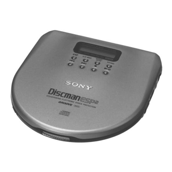
Photo: D-E705
Model Name Using Similar Mechanism
CD Mechanism Type
Optical Pick-Up Name
SPECIFICATIONS
General
Power requirements
For the area code of the model you purchased, check the upper left
side of the bar code on the package.
• Two Sony NH-DM2AA Rechargeable batteries: 2.4 V DC
• Two LR6 (size AA) batteries: 3 V DC
• AC power adaptor (DC IN 4.5 V jack):
US, Canadian, E92 model: 120 V, 60 Hz
AEP, French, East European, E13, Chinese model: 220 – 230 V,
50/60 Hz
UK model: 230 – 240 V, 50 Hz
Australian model: 240 V, 50 Hz
Tourist, E33 model: 100 – 240 V, 50/60 Hz
Hong Kong model: 220 V, 50/60 Hz
• Sony DCC-E245 car battery cord for use on car battery: 4.5 V DC
Dimensions (w/h/d) (without projecting parts and controls)
D-E700/E705:
Approx. 131.8 × 23.9 × 142.0 mm
1
(5
/
4
D-E800/E805:
Approx. 131.8 × 23.7 × 142.0 mm
1
(5
/
4
Mass (without rechargeable batteries)
Approx. 210 g (7.4 oz)
Operating temperature
5˚C – 35˚C (41˚F – 95˚F)
COMPACT DISC COMPACT PLAYER
Canadian Model
Australian Model
Chinese Model
Tourist Model
×
× 5
31
5
/
/
in.)
32
8
×
× 5
15
5
/
/
in.)
16
8
US Model
AEP Model
UK Model
E Model
D-E705/E805
D-E700/E800
NEW
CDM-2911DBA
DAX-11D

Advertisement

Table of Contents
loading

Summary of Contents for Sony D-E700

  • Page 1 1-bit quartz time-axis control Hong Kong model: 220 V, 50/60 Hz Frequency response • Sony DCC-E245 car battery cord for use on car battery: 4.5 V DC Dimensions (w/h/d) (without projecting parts and controls) 20 – 20,000 Hz dB (measured by EIAJ CP-307) –2...
  • Page 2: Table Of Contents

    DE FONCTIONNEMENT. NE REMPLACER CES COM- Use of controls or adjustments or performance of procedures POSANTS QUE PAR DES PIÈCES SONY DONT LES other than those specified herein may result in hazardous ra- NUMÉROS SONT DONNÉS DANS CE MANUEL OU diation exposure.
  • Page 3: General

    SECTION 1 This section is extracted from instruction manual. GENERAL – 3 –...
  • Page 4 – 4 –...
  • Page 5 – 5 –...
  • Page 6: Service Note

    SECTION 2 SERVICE NOTE Precautions for Checking Emission of Laser Diode NOTES ON HANDLING THE OPTICAL PICK-UP Laser light of the equipment is focused by the object lens in the BLOCK OR BASE UNIT optical pick-up so that the light focuses on the reflection surface of the disc.
  • Page 7: Disassembly

    SECTION 3 DISASSEMBLY Note: Follow the disassembly procedure in the numerical order given. CABINET (LOWER) 1 five screws (2 × 8) 4 two claws 2 Open the battery case lid. 5 cabinet (lower) 4 two claws 3 two claws INSTALLATION MAIN BOARD On installation MAIN board adjust the S301, 803, 804, and knob (H-R, AVLS).
  • Page 8: Service Mode

    SECTION 4 SERVICE MODE 4. By pressing the ^ key, focus is turned ON from focus search- Service Mode (Service program) The equipment is provided with a service program built in the ing while entering CLV-S (draw-in mode). microcomputer, like conventional models. Without disc, focus searching is repeated continuously.
  • Page 9: Electrical Adjustments

    SECTION 5 ELECTRICAL ADJUSTMENTS Precautions for Adjustment Focus bias Check 1. Before beginning adjustment, set the equipment to service Condition: mode. • Hold the set in horizontal state. After the completion of adjustment, be sure to reset the ser- vice mode. Check Procedure: oscilloscope For more information, see “Service Mode (service program) ”...
  • Page 10 Focus/Tracking Gain Adjustment The waveforms are those measured with the oscilloscope set as A servo analayzer is necessary in order to perform this adjustment shown below. exactly. • VOLT/DIV: 500 mV • TIME/DIV: 5 ms However, this gain has a margin, so even if it is slightly off, there is no problem.
  • Page 11 Adjustment Parts Location: – MAIN BOARD – (Side A) TP522 (RFO) RV401 (VCC) TP401 (VCC) RV503 FOCUS GAIN TP520 (VC) (TE) RV502 TRACKING GAIN – 11 –...
  • Page 12 • Waveforms 1 IC501 0 (TEO) (PLAY MODE) 500 mV/DIV, 1 ms/DIV Approx. 920 mVp-p 2.8 Vp-p 480 ns 2 IC501 !£ (FEO) (PLAY MODE) 500 mV/DIV, 10 ms/DIV Approx. 640 mVp-p 1.6 Vp-p 17MHz 3 IC501 @£ (RFO) (PLAY MODE) 500 mV/DIV, 1 µs/DIV 1.0 ±...
  • Page 13 9 Q405 B 5 V/DIV, 2 µs/DIV 9.2 Vp-p 5.3 µ s 0 Q405 C 2 V/DIV, 2 µs/DIV 3.8 Vp-p 5.3 µ s !¡ IC401 !∞ (CKOUT) 2 V/DIV, 2 µs/DIV 4.1 Vp-p 5.7 µ s – 23 –...
  • Page 14: Block Diagram

    • IC Block Diagrams IC301 TC9438FNEL IC302 BA3574BFS – 24 –...
  • Page 15 IC401 MPC18A26VMEL – 25 –...
  • Page 16 IC501 BA6386K – 26 –...
  • Page 17 IC502 BU9325KS IC601 SM5902AF – 27 –...
  • Page 18 IC504 MPC17A51VMEL – 28 –...
  • Page 19: 6-4. Ic Pin Function Description

    6-4. IC PIN FUNCTION DESCRIPTION • MAIN BOARD IC801 MC68HC05L24-SC440440CFU (SYSTEM CONTROLLER) Pin No. Pin Name Function — Power supply terminal (+3V) XSLDON Sled servo muting control signal output terminal “H”: sled servo muting on XBBSW Bass boost selection signal output to the headphone amplifier (IC302) Output enable signal output to the MPC17A51VMEL (IC504) “L”...
  • Page 20 Pin No. Pin Name Function SDTO Serial data output to the D-RAM controller (IC601) (for ESP) SDTI Serial data input from the D-RAM controller (IC601) (for ESP) Serial data transfer clock signal output to the D-RAM controller (IC601) (for ESP) Focus OK signal input from the RF amplifier (IC501) “H”: OK, “L”: NG BUSY Busy signal input from the BU9325KS (IC502) “L”: track jump mode, “H”: servo loop on...
  • Page 21: Exploded Views

    SECTION 7 EXPLODED VIEWS NOTE: • -XX and -X mean standardized parts, so they • Items marked “*” are not stocked since they The components identified by mark ! or dotted line with mark may have some difference from the original are seldom required for routine service.
  • Page 22 (2) CABINET SECTION-2 CDM-2911DBA Ref. No. Part No. Description Remark Ref. No. Part No. Description Remark 4-966-278-01 FOOT, RUBBER 4-993-132-01 TERMINAL BOARD (+), BATTERY 4-993-129-01 CABINET (LOWER) 4-993-134-01 PLATE, CHARGE DETECTION 4-993-131-01 KNOB (HOLD) 4-993-133-01 TERMINAL BOARD (-), BATTERY A-3306-811-A MAIN MOUNTED BOARD, COMPLETE 4-993-138-01 INSULATOR (E700/EXCEPT E705: FR) 4-993-130-01 LID, BATTERY CASE...
  • Page 23 (3) OPTICAL PICK-UP SECTION (CDM-2911DBA) not supplied M902 M901 S901 Ref. No. Part No. Description Remark Ref. No. Part No. Description Remark A-3303-970-A SCREW ASSY, FEED 1-667-512-11 SLIDE FLEXIBLE BOARD 3-318-203-11 SCREW (B1.7), TAPPING ! 110 X-4948-977-1 OPTICAL PICK-UP (DAX-11D) 4-972-163-04 SPRING, SLED 4-972-165-01 RACK 1-783-093-11 LEAD (WITH CONNECTOR)
  • Page 24: Electrical Parts List

    SECTION 8 764T MAIN ELECTRICAL PARTS LIST NOTE: • Due to standardization, replacements in the • Items marked “*” are not stocked since they The components identified by mark ! or dotted line with mark parts list may be different from the parts speci- are seldom required for routine service.
  • Page 25 MAIN Ref. No. Part No. Description Remark Ref. No. Part No. Description Remark C321 1-164-505-11 CERAMIC CHIP 2.2uF C522 1-164-004-11 CERAMIC CHIP 0.1uF C322 1-110-569-11 TANTAL. CHIP 47uF 6.3V C523 1-109-994-11 CERAMIC CHIP 2.2uF C323 1-164-156-11 CERAMIC CHIP 0.1uF C325 1-162-919-11 CERAMIC CHIP 22PF C525...
  • Page 26 MAIN Ref. No. Part No. Description Remark Ref. No. Part No. Description Remark < CONNECTOR > IC505 8-759-387-31 IC TC75S55F (TE85R) IC507 8-759-082-60 IC TC7S66FU CN501 1-779-761-21 CONNECTOR, FPC (ZIF) 14P CN502 1-779-760-11 PIN, CONNECTOR 2P IC601 8-759-484-37 IC SM5902AF CN503 1-784-342-21 HOUSING, CONNECTOR 2P IC602...
  • Page 27 MAIN Ref. No. Part No. Description Remark Ref. No. Part No. Description Remark Q512 8-729-029-07 TRANSISTOR DTC124TUA-T106 R434 1-216-861-11 METAL CHIP 2.2M 1/16W Q513 8-729-028-74 TRANSISTOR DTA114TUA-T106 Q601 8-729-029-06 TRANSISTOR DTC124EUA-T106 R435 1-216-859-11 RES, CHIP 1.5M 1/16W Q602 8-729-924-28 TRANSISTOR DTA123YU R436 1-216-854-11 METAL CHIP 560K...
  • Page 28 MAIN Ref. No. Part No. Description Remark Ref. No. Part No. Description Remark R601 1-216-864-11 METAL CHIP 1/16W S804 1-762-078-11 SWITCH, SLIDE (HOLDc) R602 1-216-833-11 METAL CHIP 1/16W R603 1-216-833-11 METAL CHIP 1/16W < TRANSFORMER > R604 1-216-833-11 METAL CHIP 1/16W T401 1-431-557-11 TRANSFORMER, DC-DC CONVERTER...
  • Page 29 Ref. No. Part No. Description Remark 3-861-194-21 MANUAL, INSTRUCTION (RUSSIAN, CZECH) (E705: EE) 3-861-194-31 MANUAL, INSTRUCTION (POLISH, HUNGARIAN) (E705: EE) 3-861-209-11 MANUAL, INSTRUCTION (CHINESE) (E13, HK, CH) 3-861-209-21 MANUAL, INSTRUCTION (ENGLISH) (E13, HK, CH) 4-993-659-01 CASE, CARRYING 8-953-171-91 HEADPHONE MDR-ED136MP/K1 SET (E705: EXCEPT US/E805: CND, UK, E, FR, CH) 8-953-276-90 HEADPHONE MDR-24SP SET (E805: US) 8-953-342-93 HEADPHONE MDR-24/K1 SET (E705: US)
  • Page 30 D-E700/E705/E800/E805 Sony Corporation 98A0591-1 Printed in Japan © 1998. 1 9-923-293-11 Personal A&V Products Company Published by Quarity Engineering Dept. – 40 – (Shibaura)

This manual is also suitable for:

D-e800D-e805D-e705Discman esp2 d-e700Discman esp2 d-e705Discman esp2 d-e800 ... Show all

Table of Contents