
Related Manuals for Goldstar GWHD6500R


Summary of Contents for Goldstar GWHD6500R
-
Page 1: Room Air Conditioner
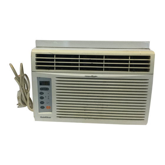
ROOM AIR CONDITIONER SERVICE MANUAL CAUTION BEFORE SERVICING THE UNIT, READ THE SAFETY PRECAUTIONS IN THIS MANUAL. � � � � � � � � � � ,GWHD6500RY6 GWHD6500R MODEL:... -
Page 2: Table Of Contents
CONTENTS 1. PREFACE ..................................3 1.1 FEATURES ..................................3 1.2 SPECIFICATIONS ................................3 1.3 SAFETY PRECAUTIONS ..............................3 1.4 INSULATION RESISTANCE TEST ............................ 3 1.5 LOCATIONS OF CONTROLS ............................4 2. DISASSEMBLY INSTRUCTIONS ........................6 2.1 MECHANICAL PARTS ..............................6 2.1.1 FRONT GRILLE ............................... -
Page 3: Preface
DESIGNED FOR COOLING ONLY POWERFUL AND INCREDIBLE COOLING TOP-DOWN CHASSIS FOR THE SIMPLE INSTALLATION AND SERVICE WASHABLE ONE-TOUCH FILTER COMPACT SIZE 1.2 SPECIFICATIONS MODELS GWHD6500R GWHD6500RY6 ITEMS 6,500 COOLING CAPACITY (BTU/h) POWER SUPPLY (Phase, V, Hz) 1�, 115V, 60HZ INPUT (W) OPERATING CURRENT (AMP.) -
Page 4: Locations Of Controls
1.5 LOCATIONS OF CONTROLS 1.5.1 CONTROLS TEMPERATURE SETTING This button can automatically control the temperature of the room. The temperature can be set within a range of 60 F(16 C) to 86 F(30 C) by 1 F(1 C). Select the lower number for lower temperature of the room. ENERGY SAVER The fan stops when the compressor stops cooling. -
Page 5: Remote Controller
1.5.2 REMOTE CONTROLLER POWER To turn the Set ON, push the button. To turn the Set OFF, push the button again. This button takes priority over any other buttons. When you first turn it on, the Set is on the High cool mode and the temp. at 72� F(22� C). TEMPERATURE SETTING This button can automatically control the temperature of the room. -
Page 6: Disassembly Instructions
2. DISASSEMBLY INSTRUCTIONS 2.1 MECHANICAL PARTS 2.1.1 FRONT GRILLE Figure 1 1. Disconnect the unit from source of power. 2. Using a screwdriver, remove the screw that secures the front grille to control board. (See Figure 1) 3. Push the front grille up from the bottom. Pull the top of the front grille away from the cabinet as the top tabs lift out of their slots. -
Page 7: Air Handling Parts
2.2 AIR HANDLING PARTS Figure 6 2.2.1 AIR GUIDE UPPER 1. Disconnect the unit from the power source. 2. Remove the front grille. (Refer to Section 2.1.1) 3. Remove the cabinet. (Refer to Section 2.1.2) 4. Remove the control board. (Refer to Section 2.1.3) 5. -
Page 8: Motor
2.2.3 MOTOR Figure 10 1. Disconnect the unit from the power source. 2. Remove the front grille. (Refer to Section 2.1.1) 3. Remove the cabinet. (Refer to Section 2.1.2) 4. Remove the control board. (Refer to Section 2.1.3) 5. Remove the air guide upper. (Refer to Section 2.2.1) 6. -
Page 9: Compressor
2.3.2 COMPRESSOR Figure 14 1. Remove the front grille and cabinet. (Refer to Section 2.1.2) 2. Discharge the refrigerant by using a refrigerant recovery system. 3. Remove the overload protector. (Refer to Section 2.3.1) 4. After discharging the unit completely, unbrace the suction and discharge pipes at the compressor connections. -
Page 10: Power Cord
2.3.6 POWER CORD Figure 18 1. Disconnect the unit from source of power. 2. Remove the front grille. (Refer to Section 2.1.1) 3. Remove the cabinet. (Refer to Section 2.1.2) 4. Remove 2 screws that secure control board to base pan and air guide. (Refer to Section 2.1.3) 5. -
Page 11: Capillary Tube
2.4.3 CAPILLARY TUBE 6-4. Remove the hose from the vacuum pump and place it on the charging cylinder. See figure 1. Remove the cabinet. (Refer to Section 2.1.2) 20B. Open valve C. 2. Discharge the refrigerant by using a refrigerant Discharge the line at the manifold connection. - Page 12 Equipment needed: Vacuum pump, charging cylinder, manifold gauge, brazing equipment, pinch-off tool capable of making a vapor proof seal, leak detector, tubing cutter, hand tools to remove components and service valve. COMPOUND GAUGE MANIFOLD GAUGE CONDENSER SEE INSETS (HIGH PRESSURE SIDE) BELOW COMPRESSOR EVAPORATOR...
-
Page 13: Installation
3. INSTALLATION This air conditioner is designed with a button-down chassis so it can be easily installed in a window. 3.1 SELECT THE BEST LOCATION 1. To prevent vibration and noise, make sure the unit is installed securely and firmly. 2. -
Page 14: Before Installation
Installation Kit (Some models) HARDWARE TYPE A: 11EA TYPE B: 5EA TYPE C: 3EA DRAIN PIPE (SHORT SCREW) (WOOD SCREW) (L BACKET) TYPE D: 1EA TYPE E: 1EA TYPE F: 2EA TYPE G: 1EA (SEAL STRIP) (SASH SEAL) (GUIDE PANEL) (SUPPORT BACKET) (Adhesive backed) (Not adhesive backed) -
Page 15: How To Secure The Drain Pipe
IMPORTANT : When the air conditioner drops into the L bracket, the air conditioner will be centered in window opening as shown in Figure. 28. b. While steadying the air conditioner, carefully bring the window sash down behind the upper guide of the air conditioner, as shown in Figure. -
Page 16: Electrical Data
REMOVAL FROM WINDOW Turn the air conditioner off, disconnect the power cord, remove the L bracket, the screws and support bracket installed through the top and bottom of the guide panels, and save for reinstallation later. Close the guide panels. Keeping a firm grip on the air conditioner, raise the sash, and carefully tilt the air conditioner backward, draining any condensate. -
Page 17: Piping System
4.2 PIPING SYSTEM CONDENSER COILS MOTOR CAPILLARY TUBE TURBO FAN EVAPORATOR COILS Following is a brief description of the important components and their function in what is called the refrigeration system. Reference should be made to Figure 33 to follow the refrigerating cycle and the flow of the refrigerant in the cooling cycle. -
Page 18: Troubleshooting Guide
4.3 TROUBLESHOOTING GUIDE In general, possible trouble is classified in two kinds. The one is called Starting Failure which is caused by an electrical defect. The other is Ineffective Air Con- ditioning caused by a defect in the refrigeration circuit and improper application. Unit is running but cooling is ineffective. - Page 19 Fails to Start Check of circuit breaker Check of power source. and fuse. Check of control panel Check control panel. setting. Compressor fails only to Fan only fails to start. start. Improper wiring. Improper thermistor Drop of power voltage. setting Defect of fan motor capacitor.
- Page 20 ELECTRIC PARTS TROUBLESHOOTING GUIDE: Possible Trouble 1 • The unit does not operate. • Check the Fuse. Is the Trans output power • Check the wiring diagram. AC 115V? • Check the Main Is the Trans output power Is shorted the Trans. output? P.W.B pattern.
- Page 21 Possible Trouble 2 • The compressor does not operate. Is Temp. setting set lower than Room • Set the Temp. setting to higher Temp. Temp.-0.5°C? Is the voltage No.10 Is the voltage N0.7 of Is the Unit for 3 minutes of IC01M 0V? IC01M DC 5V? delay?
- Page 22 • Romote controller does not operate. Possible Trouble 5 Is the voltage of Battery • Exchange the battery. about over 2.3V? Is the voltage No.16 • Check the P.W.B pattern. of CN-DISP1 on Main P.W.B Ass'y DC 5V? • Connect connector to Is the connection of CN-DISP1 exactly.
- Page 23 ROOM AIR CONDITIONER VOLTAGE LIMITS NAME PLATE RATING MINIMUM MAXIMUM 115V ± 10% 103.5V 126.5V COMPLAINT CAUSE REMEDY Fan motor will not run. No power Check voltage at outlet. Correct if none. Power supply cord Check voltage to rotary switch. If none, check power supply cord.
- Page 24 COMPLAINT CAUSE REMEDY Fan motor noise. If cracked, out of balance, or partially missing, replace it. Blower If cracked, out of balance, or partially missing, replace it. Loose set screw Tighten it. Worn bearings If knocking sounds continue when running or loose, replace the motor.
- Page 25 COMPLAINT CAUSE REMEDY Compressor cycles on Fan motor If not running, determine the cause. Replace if overload required. Condenser air flow Remove the cabinet, inspect the interior surface restriction of the condenser. If restricted, clean carefully with a vacuum cleaner (do not damage fins) or brush.
-
Page 26: Schematic Diagram
5. SCHEMATIC DIAGRAM 5.1 CIRCUIT DIAGRAM LOCATION Q'TY DESCRIPTION PER SET POWER CORD ASSEMBLY FAN MOTOR COMPRESSOR DISPLAY P.W.B ASSEMBLY MAIN P.W.B ASSEMBLY THERMISTOR CAPACITOR OVERLOAD PROTECTOR - 26 -... -
Page 27: Electronic Control Device
5.2 ELECTRONIC CONTROL DEVICE —27—... -
Page 28: Components Location(For Main P.w.b Asm)
5.3 COMPONENTS LOCATION 5.4 COMPONENTS LOCATION (FOR MAIN P.W.B ASM) (FOR DISPLAY P.W.B ASM) —28—... -
Page 29: Exploded View
6. EXPLODED VIEW 137215 W48602 559010 130910 148000 554030 149980 349480 132111-2 267110 132111-1 135312 352390-2 159900-2 145200 359012 346811 W48602 352390-1 159900-1 152302 354210 130410 135313 W0CZZ 264110 552111 352115 567502 352113 554160 268714 263230 35211A 550140 238310 268712 249950 - 29 -... -
Page 30: Service Parts List
7. SERVICE PARTS LIST PART NO LOCATION DESCRIPTION GWHD6500RY6 GWHD6500R REMARKS 3041A10011E 130410 BASE ASSEMBLY,SINGLE 3091A30016C 130910 CABINET ASSEMBLY,SINGLE 3211AR3239A 132111-1 FRAME ASSEMBLY 132111-2 FRAME ASSEMBLY 3211AR3239B 3531AR1644H 135312 GRILLE ASSEMBLY, FRONT(SINGLE) 135313 GRILLE ASSEMBLY, INLET 3530A10039A 137215 GUIDE 5210AR3196C... - Page 31 October, 2005 P/No.: 3828A20529B Printed inThailand...
Need help?
Do you have a question about the GWHD6500R and is the answer not in the manual?
Questions and answers