Table of Contents
Advertisement
Quick Links
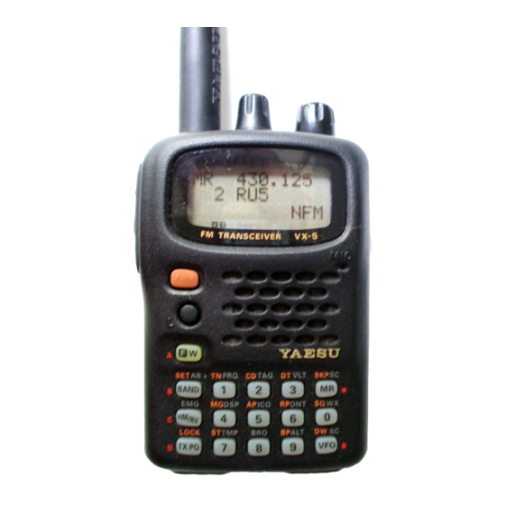
50/144/430 MHz Triple-Band
Heavy Duty FM Transceiver
VX-5R
Technical Supplement
©2003 VERTEX STANDARD CO., LTD.
Specification.......................................................................................................................................... 2
Exploded View & Miscellaneous Parts ............................................................................................ 3
Block Diagram ...................................................................................................................................... 5
Interconnection Diagram .................................................................................................................... 6
Circuit Description ............................................................................................................................. 7
Alignment ............................................................................................................................................ 11
Board Unit (Schematics, Layouts & Parts)
Cntl Unit ...................................................................................................................................................................... 17
Af Unit ............................................................................................................................................................................ 35
Rf Unit ............................................................................................................................................................................ 51
Vco Unit ........................................................................................................................................................................ 73
Downloaded by
RadioAmateur.EU
E126990A
Introduction
This manual provides the technical information necessary for servicing
the VX-5R Triple-Band Heavy Duty FM Transceiver.
Servicing this equipment requires expertise in handing surface-mount
chip components. Attempts by non-qualified persons to service this
equipment may result in permanent damage not covered by the war-
ranty, and may be illegal in some countries.
Two PCB layout diagrams provided for each double-sided board in
this transceiver. Each side of the board is referred to by the type of the
majority of components installed on that side ("Side A" or "Side B"). In
most cases one side has only chip components, and the other has ei-
ther a mixture of both chip and leaded components (trimmers, coils,
electrolytic capacitors, ICs, etc.), or leaded components only.
While we believe the information in this manual to be correct, VER-
TEX STANDARD assumes no liability for damage that may occur as a
result of typographical or other errors that may be present. Your coop-
eration in pointing out any inconsistencies in the technical informa-
tion would be appreciated.
Contents
VERTEX STANDARD CO., LTD.
4-8-8 Nakameguro, Meguro-Ku, Tokyo 153-8644, Japan
VERTEX STANDARD
US Headquarters
10900 Walker Street, Cypress, CA 90630, U.S.A.
International Division
8350 N.W. 52nd Terrace, Suite 201, Miami, FL 33166, U.S.A.
YAESU EUROPE B.V.
P.O. Box 75525, 1118 ZN Schiphol, The Netherlands
YAESU UK LTD.
Unit 12, Sun Valley Business Park, Winnall Close
Winchester, Hampshire, SO23 0LB, U.K.
VERTEX STANDARD HK LTD.
Unit 5, 20/F., Seaview Centre, 139-141 Hoi Bun Road,
Kwun Tong, Kowloon, Hong Kong
Advertisement
Table of Contents

Related Manuals for Vertex VX-5R


Summary of Contents for Vertex VX-5R
-
Page 1: Circuit Description
Kwun Tong, Kowloon, Hong Kong Introduction This manual provides the technical information necessary for servicing the VX-5R Triple-Band Heavy Duty FM Transceiver. Servicing this equipment requires expertise in handing surface-mount chip components. Attempts by non-qualified persons to service this equipment may result in permanent damage not covered by the war- ranty, and may be illegal in some countries. -
Page 2: Specification
Specifications General Downloaded by Frequency Ranges: Rx: 0.5 - 1.8 MHz (BC Band) RadioAmateur.EU 1.8 - 16 MHz (SW Band) 48 - 59 MHz (50 MHz HAM) 59 - 108 MHz (FM) 108 - 137 MHz (Air Band) 137 - 174 MHz (144 MHz HAM) 174 - 222 MHz (VHF-TV) 222 - 420 MHz (ACT1: Action Band 1) 420 - 470 MHz (430 MHz HAM) -
Page 3: Exploded View & Miscellaneous Parts
Exploded View & Miscellaneous Parts RA0142600 RA0139400 DOUBLE FACE (WINDOW) WINDOW YAESU P/N Description Qty. À U9900063 TAPTITE SCREW 2X3.3Ni CP6330003 (USA) CP6330004 (EXPORT) Á U44104002 TAPTITE SCREW M2X4Ni CP6330005 (GERMANY) Â U44115002 TAPTITE SCREW M2X15Ni CP6330006 (KOREA) CP6330008 (VX 5RS) Ã... - Page 4 Note: Downloaded by RadioAmateur.EU...
-
Page 5: Block Diagram
Downloaded by Block Diagram RadioAmateur.EU... -
Page 6: Interconnection Diagram
Downloaded by RadioAmateur.EU Interconnection Diagram... -
Page 7: Circuit Description
Circuit Description The VX-5R internal assembly consists of the RF Unit, (3) 435 MHz Band and 222 ~ 540 MHz Reception Control (CNTL) Unit, and the AF Unit. The RF Unit con- Received signals between 430 and 450 MHz pass... - Page 8 Circuit Description quency band-pass filters. By changing the electrostatic filtered by a variable band-pass filter composed of D3018, capacitance of the varactors, optimum filter characteris- D3019 (HVC362´2), L3023, D3021 (1T412), C3068, L3026, tics are provided for each specific operating frequency. D3022, and D3023 (HVC362´2).
- Page 9 Circuit Description the input voltage drops below the threshold, normally due PTT switch, pin 13 (“TX”) goes high. This control signal is to the presence of a carrier, squelch gate Q2020 delivered to the RF Unit, where it switches Q3054 (UMW1) (2SJ144GR) turns on, allowing any demodulated audio and Q3051 (CPH6102) to produce the “TX”...
- Page 10 Circuit Description PLL Frequency Synthesizer (6) 50 MHz Band Transmission Modulating audio from the CNTL Unit passes through PLL IC Q3021 on the RF Unit consists of a data shift deviation-setting potentiometer VR1001 to “50 MHz register, reference frequency divider, phase comparator, MOD”...
-
Page 11: Alignment
Alignment Introduction Required Test Equipment The VX-5R is carefully aligned at the factory for the spec- RF Signal Generator with calibrated output level at 500 MHz ified performance across the amateur band. Realignment Deviation Meter (linear detector) should therefore not be necessary except in the event of a In-line Wattmeter with 5% accuracy at 500 MHz component failure. - Page 12 AF Unit, if necessary, so the counter frequency is within Inject a 1 kHz audio tone at a level of 80 mV (rms) to the 100 Hz of the displayed frequency on the VX-5R. MIC jack. Transmit, and adjust VR1003 to obtain ±4.2-4.5 kHz de- 50 MHz band Tx Deviation Adjustment viation, as indicated on the deviation meter (±3.7-4.0 kHz...
- Page 13 Alignment Internal System Alignment Routine This uses a programmed routine in the transceiver which DIAL to select the next setting. simplifies many previously complex discrete component Squelch Preset Tight (TIGH SQL) [54] settings and adjustments with digitally-controlled settings Adjust the generator level to –4.0 dBµ, then presses the via front panel buttons and LCD indications.
- Page 14 Alignment 144 MHz Band Alignment L1 Tx Power Adjustment (L1 POWER) [21] Squelch Hysteresis Adjustment (HIS SQL) [0] Transmit, and adjust the output power level for 0.2-0.4 Press the MR button, then rotate the DIAL for minimum W by rotating the DIAL, then presses the MR button twice. squelch hysteresis.
- Page 15 Alignment L3 Tx Power Adjustment (L3 POWER) [119] L1 Tx Power Adjustment (L1 POWER) [35] Transmit, and adjust the output power level for 2.3-2.7 Transmit, and adjust the output power level for 0.2-0.4 W by rotating the DIAL, then presses the MR button W by rotating the DIAL, then presses the MR button twice.
- Page 16 Alignment Note:...
-
Page 17: Cntl Unit
Downloaded by CNTL Unit RadioAmateur.EU Circuit Diagram 4.0V(4.0V) 2.0V(2.0V) 3.0V(3.0V) 1.5V(1.5V) 1.6V(1.6V) 5.1V(5.1V) 1.0V(1.0V) 6.1V(6.1V) 4.3V(4.3V) 4.6V (4.6V) 1.7V(1.7V) 6.0V(6.0V) 3.0V(3.0V) 6.4V(6.4V) 9.0V(9.0V) 3.0V(3.0V) 3.0V(1.2V) 0.2V(0V) 0V(0V) 1.0V(0V) 0V(3.0V) 0V(0V)[2.6V] 0V(0V){2.6V} BUSY LED ON: 3.0V 0V(0V) 3.0V(3.0V) 0V(0V) 0V(0V) 2.9V(2.9V) 0V(0V) 3.0V(3.0V) 0V(0V) - Page 18 CNTL Unit Note:...
- Page 19 CNTL Unit Parts Layout 2SD1801S (Q1002) DTC124TE (05) (Q1008) Downloaded by RadioAmateur.EU Side A...
- Page 20 CNTL Unit Parts Layout NJM3403AV (Q1014) M24C64-WMN (Q1009) HD6473877UX (Q1003) BA10358FV S-81230SG (QB) S-80730SN (DT) (Q1015) (Q1013) (Q1011, 1017) RH5RH651A BA030LBSG UMD2N (D2) (Q1016) (Q1012) (Q1010) CPH6102 (AB) UMW1 (W1) DTC144EE (26) (Q1019) (Q1018) (Q1007) 2SC4617 (BR) DTA144EE (16) DTC143ZE (E23) (Q1001) (Q1005) (Q1006)
- Page 21 CNTL Unit (Lot 2 ~) Circuit Diagram...
- Page 22 CNTL Unit (Lot 2 ~) Note:...
- Page 23 CNTL Unit (Lot 2 ~) Parts Layout 2SD1801S (Q1002) DTC124TE (05) (Q1008) Side A...
- Page 24 CNTL Unit (Lot 2 ~) Parts Layout NJM3403AV (Q1014) M24C64-WMN (Lot. 1~) AT24C64N (Lot. 18~) HD6473877UX (Lot. 1~) (Q1009) HD6433876UB17X (Lot. 2~, USA) HD6433876UB18X (Lot. 2~, EXP) HD6433876UB18X (Lot. 4~, GER) HD6433876UB25X (Lot. 6~, USA) HD6433876UB23X (Lot. 12~, EXP, GER) (Q1003) BA10358FV (Q1015)
- Page 25 CNTL Unit (Lot 24 ~) Circuit Diagram...
- Page 26 CNTL Unit (Lot 24 ~) Note:...
- Page 27 CNTL Unit (Lot 24 ~) Parts Layout 2SD1801S (Q1002) DTC124TE (05) (Q1008) Side A...
- Page 28 CNTL Unit (Lot 24 ~) Parts Layout NJM3403AV (Q1014) M24C64-WMN (Lot. 1~) AT24C64N (Lot. 18~) HD6473877UX (Lot. 1~) (Q1009) HD6433876UB17X (Lot. 2~, USA) HD6433876UB18X (Lot. 2~, EXP) HD6433876UB18X (Lot. 4~, GER) HD6433876UB25X (Lot. 6~, USA) HD6433876UB23X (Lot. 12~, EXP, GER) HD6473877UX (R0453) (Lot.
- Page 29 CNTL Unit Parts List REF. DESCRIPTION VALUE TOL. MFR’S DESIG VXSTD P/N VERS. LOT. SIDE. LAY ADR. *** CNTL UNIT *** PCB with Components (USA) CB0520002 VERSION A2 PCB with Components (EXPORT) CB0520003 VERSION A1 PCB with Components (EXPORT) CB0520004 VERSION A2 PCB with Components (EXPORT) CB0520005 VERSION A3...
- Page 30 CNTL Unit Downloaded by RadioAmateur.EU REF. DESCRIPTION VALUE TOL. MFR’S DESIG VXSTD P/N VERS. LOT. SIDE. LAY ADR. C 1031 CHIP CAP. GRM39F105Z10PT K22105001 C 1032 CHIP CAP. GRM39F105Z10PT K22105001 C 1033 CHIP CAP. GRM39F105Z10PT K22105001 C 1034 CHIP CAP. GRM40B105K10PT K22100802 C 1035 CHIP CAP.
- Page 31 CNTL Unit REF. DESCRIPTION VALUE TOL. MFR’S DESIG VXSTD P/N VERS. LOT. SIDE. LAY ADR. C 1070 CHIP CAP. 0.001uF GRM36B102K50PT K22178809 C 1071 AL.ELECTRO.CAP. 47uF ECEV1CA470WR K48120013 C 1072 CHIP TA.CAP. 10uF 6.3V TESVSP0J106M-8R K78080055 C 1073 CHIP TA.CAP. 22uF TEMSVA0G226M-8R K78060023...
- Page 32 CR05-222J-H J24189281 R 1003 CHIP RES. 1/16W 5% CR05-105J-H J24189313 R 1004 CHIP RES. 1/16W 5% CR05-471J-H J24189273 R 1005 CHIP RES. 2.2k 1/16W 5% CR05-222J-H J24189281 R 1007 CHIP RES. 1/16W 5% CR05-105J-H J24189313 Please contact VERTEX STANDARD. ø...
- Page 33 CNTL Unit REF. DESCRIPTION VALUE TOL. MFR’S DESIG VXSTD P/N VERS. LOT. SIDE. LAY ADR. R 1009 CHIP RES. 1/16W 5% CR05-473J-H J24189297 R 1010 CHIP RES. 5.6k 1/16W 5% CR05-562J-H J24189286 R 1011 CHIP RES. 100k 1/16W 5% CR05-104J-H J24189301 R 1013 CHIP RES.
- Page 34 CNTL Unit REF. DESCRIPTION VALUE TOL. MFR’S DESIG VXSTD P/N VERS. LOT. SIDE. LAY ADR. R 1073 CHIP RES. 1.8k 1/16W 5% CR05-182J-H J24189280 R 1074 CHIP RES. 1/16W 5% CR05-223J-H J24189293 R 1075 CHIP RES. 100k 1/16W 5% CR05-104J-H J24189301 R 1076 CHIP RES.
- Page 35 AF Unit Circuit Diagram 0V(0V) 7.2V(0V) 0.5V(0.4V) 2.6V(0V) 3.0V(0V) 3.0V(0V) 6.5V 0.7V(0V) 0.4V(0.3V) 2.4V(0V) 1.4V 0V(0V) 3.4V(0.4V) 2.3V(0V) 3.0V(0V) (0.2V) 0V(0V)[2.6V] 1.2V(0V) 0V(0V) 7.2V(0V) 0V(2.8V) 1.4V (0.2V) 0.4V(0.3V) 1.3V(0.5V) 1.2V(0V) 1.8V(0V) 0V(0V) 0.6V(0.6V) 1.2V(1.2V) 1.6V (1.6V) 0V(0V) 3.0V (3.0V) 1.1V(1.1V) (3.0V) 3.0V(0V) 3.0V(0V)
- Page 36 AF Unit Parts Layout Side A Side B TA7792F TDA7233D TK10930V (Q2006) (Q2019) FC119 (119) UMX3N (X3) CPH6102 (AB) DTC144EE (26) DAN222 (N) (Q2005) (D2012) (Q2025) (Q2011) (Q2015) (Q2001, 2028) 2SK2170 (JA) HN1J02FU (KS) (Q2023) 2SJ144GR (VG) UMA2N (A2) (Q2020) 2SC4400 (RT4) (Q2010) DTC143ZE (E23)
- Page 37 AF Unit (Lot 2~) Circuit Diagram Downloaded by RadioAmateur.EU...
- Page 38 AF Unit (Lot 2~) Parts Layout Side A Side B TA7792F TDA7233D TK10930V (Q2006) (Q2019) FC119 (119) UMX3N (X3) CPH6102 (AB) DTC144EE (26) DAN222 (N) (Q2005) (D2012) (Q2025) (Q2011) (Q2015) (Q2001, 2028) 2SK2170 (JA) HN1J02FU (KS) (Q2023) 2SJ144GR (VG) UMA2N (A2) (Q2020) 2SC4400 (RT4) (Q2010)
- Page 39 AF Unit (Lot 5~) Circuit Diagram...
- Page 40 AF Unit (Lot 5~) Parts Layout Side A Side B Downloaded by RadioAmateur.EU TA7792F TDA7233D TK10930V (Q2006) (Q2019) FC119 (119) UMX3N (X3) CPH6102 (AB) DTC144EE (26) DAN222 (N) (Q2005) (D2012) (Q2025) (Q2011) (Q2015) (Q2001, 2028) 2SK2170 (JA) HN1J02FU (KS) (Q2023) 2SJ144GR (VG) (Lot.
- Page 41 AF Unit (Lot 17~) Circuit Diagram...
- Page 42 AF Unit (Lot 17~) Parts Layout Side A Side B TA7792F TDA7233D TK10930V (Q2006) (Q2019) FC119 (119) UMX3N (X3) CPH6102 (AB) DTC144EE (26) DAN222 (N) (Q2005) (D2012) (Q2025) (Q2011) (Q2015) (Q2001, 2028) 2SK2170 (JA) HN1J02FU (KS) (Q2023) 2SJ144GR (VG) (Lot. 1~) UMA2N (A2) 2SJ364 (4M) (Lot.
- Page 43 AF Unit Parts List REF. DESCRIPTION VALUE TOL. MFR’S DESIG VXSTD P/N VERS. LOT. SIDE. LAY ADR. *** AF UNIT *** PCB with Components CB0521001 Printed Circuit Board FR003040C Printed Circuit Board FR003040D Printed Circuit Board FR003040E Printed Circuit Board FR003040F C 2001 CHIP CAP.
- Page 44 AF Unit REF. DESCRIPTION VALUE TOL. MFR’S DESIG VXSTD P/N VERS. LOT. SIDE. LAY ADR. C 2040 CHIP CAP. 39pF GRM36CH390J50PT K22178226 C 2041 CHIP CAP. 0.01uF CM05W5R103K16AH K22128805 C 2041 CHIP CAP. 0.01uF GRM36B103K16PT K22128804 C 2042 CHIP CAP. 0.01uF CM05W5R103K16AH K22128805...
- Page 45 AF Unit REF. DESCRIPTION VALUE TOL. MFR’S DESIG VXSTD P/N VERS. LOT. SIDE. LAY ADR. C 2082 CHIP CAP. 39pF GRM36CH390J50PT K22178226 C 2083 CHIP TA.CAP. TEMSVA1E105M-8R K78140013 C 2084 CHIP CAP. 220pF GRM36CH221J25PT K22148203 C 2085 CHIP CAP. 0.001uF CM05W5R102K50AH K22178820 C 2085 CHIP CAP.
- Page 46 AF Unit REF. DESCRIPTION VALUE TOL. MFR’S DESIG VXSTD P/N VERS. LOT. SIDE. LAY ADR. C 2131 CHIP CAP. 0.047uF GRM39B473K16PT K22124804 C 2132 CHIP CAP. 0.047uF GRM39B473K16PT K22124804 C 2133 CHIP CAP. 0.1uF GRM39B104K16PT K22124805 C 2134 CHIP CAP. 33pF GRM36CH330J50PT K22178224...
- Page 47 AF Unit REF. DESCRIPTION VALUE TOL. MFR’S DESIG VXSTD P/N VERS. LOT. SIDE. LAY ADR. Q 2008 TRANSISTOR 2SC4400-4-TL G3344008D Q 2009 TRANSISTOR UMG2N TR G3070088 Q 2010 FET HN1J02FU(TE85L) G3070221 Q 2011 TRANSISTOR UMX3N TR G3070218 Q 2012 TRANSISTOR UMD2N TR G3070076 Q 2013 TRANSISTOR...
- Page 48 AF Unit REF. DESCRIPTION VALUE TOL. MFR’S DESIG VXSTD P/N VERS. LOT. SIDE. LAY ADR. R 2038 CHIP RES. 1/16W 5% CR05-103J-H J24189289 R 2039 CHIP RES. 1/16W CR05-000-H J24189248 R 2039 CHIP RES. 1/16W 5% CR05-100J-H J24189253 R 2039 CHIP RES. 1/16W 5% CR05-101J-H J24189265...
- Page 49 AF Unit REF. DESCRIPTION VALUE TOL. MFR’S DESIG VXSTD P/N VERS. LOT. SIDE. LAY ADR. R 2098 CHIP RES. 1/16W 5% CR05-471J-H J24189273 R 2099 CHIP RES. 1/16W 5% RMC1/16 000JATP J24185000 S 2001 ROTARY ENCODER TP70N00E20 Q9000723 S 2001 ROTARY ENCODER TP70N17E20 Q9000726 T 2001 CHIP TRANS.
- Page 50 AF Unit Note:...
- Page 51 RF Unit Circuit Diagram 800M RX: 0.63V 800M RX: 0.72V 800M RX: 2.0V 0V(2.2V) 7.3V(6.7V) 0V(4.86V) 7.3V(6.7V) (0V) (0V) (0V) 800M RX: 2.1V (0V) (1.44V) UHF RX: 2.06V (0V) 0V(6.2V) UHF RX: 0.73V UHF RX: 1.81V (0V) (0V) UHF RX: 1.8V (0V) UHF RX: 0.72V UHF RX: 0.5V...
- Page 52 RF Unit Parts Layout Downloaded by RadioAmateur.EU Side A BA10358FV FQ7925 (Q3028) TC75S51F (SC) UMB3N (B3) (Q3021) UMD2N (D2) CPH6102 (AB) (Q3056) (Q3045, 3046, 3047) (Q3025) (Q3044, 3051) 2SC4400 (RT4) DTA124EE (15) UMW1 (W1) UMD6N (D6) UMX3N (X3) UMZ1N (Z1) (Q3009, 3017) (Q3026) (Q3035, 3054)
- Page 53 RF Unit (Lot 2 ~) Circuit Diagram...
- Page 54 RF Unit (Lot 2 ~) Parts Layout Side A BA10358FV FQ7925 (Q3028) TC75S51F (SC) UMB3N (B3) (Q3021) UMD2N (D2) CPH6102 (AB) (Q3056) (Q3045, 3046, 3047) (Q3025) (Q3044, 3051) 2SC4400 (RT4) DTA124EE (15) UMW1 (W1) UMD6N (D6) UMX3N (X3) UMZ1N (Z1) (Q3009, 3017) (Q3026) (Q3035, 3054)
- Page 55 RF Unit (Lot 5 ~) Circuit Diagram...
- Page 56 RF Unit (Lot 5 ~) Parts Layout Side A BA10358FV FQ7925 (Q3028) TC75S51F (SC) UMB3N (B3) (Q3021) UMD2N (D2) CPH6102 (AB) (Q3056) (Q3045, 3046, 3047) (Q3025) (Q3044, 3051) 2SC4400 (RT4) DTA124EE (15) UMW1 (W1) UMD6N (D6) UMX3N (X3) UMZ1N (Z1) (Q3009, 3017) (Q3026) (Q3035, 3054)
- Page 57 RF Unit (Lot 17 ~) Circuit Diagram Downloaded by RadioAmateur.EU...
- Page 58 RF Unit (Lot 17 ~) Parts Layout Side A BA10358FV FQ7925 (Q3028) TC75S51F (SC) UMB3N (B3) (Q3021) UMD2N (D2) CPH6102 (AB) (Q3056) (Q3045, 3046, 3047) (Q3025) (Q3044, 3051) 2SC4400 (RT4) DTA124EE (15) UMW1 (W1) UMD6N (D6) UMX3N (X3) UMZ1N (Z1) (Q3009, 3017) (Q3026) (Q3035, 3054)
- Page 59 RF Unit (Lot 41~) Circuit Diagram...
- Page 60 RF Unit (Lot 41~) Parts Layout Downloaded by RadioAmateur.EU Side A BA10358FV FQ7925 (Q3028) TC75S51F (SC) UMB3N (B3) (Q3021) UMD2N (D2) CPH6102 (AB) (Q3056) (Q3045, 3046, 3047) (Q3025) (Q3044, 3051) 2SC4400 (RT4) DTA124EE (15) UMW1 (W1) UMD6N (D6) UMX3N (X3) UMZ1N (Z1) (Q3009, 3017) (Q3026)
- Page 61 RF Unit Parts List REF. DESCRIPTION VALUE TOL. MFR’S DESIG VXSTD P/N VERS. LOT. SIDE. LAY ADR. *** RF UNIT *** PCB with Components (w/ VCO UNIT) CP6321001 PCB with Components (w/ VCO UNIT) CP6321003 USA PCB with Components (w/ VCO UNIT) CP6321004 EXPORT PCB with Components (w/ VCO UNIT) CP6321005 GERMANY...
- Page 62 RF Unit REF. DESCRIPTION VALUE TOL. MFR’S DESIG VXSTD P/N VERS. LOT. SIDE. LAY ADR. C 3049 CHIP CAP. 0.001uF CM05W5R102K50AH K22178820 C 3049 CHIP CAP. 0.001uF GRM36B102K50PT K22178809 C 3051 CHIP CAP. 22pF GRM36CH220J50PT K22178220 C 3052 CHIP CAP. 22pF GRM36CH220J50PT K22178220...
- Page 63 RF Unit REF. DESCRIPTION VALUE TOL. MFR’S DESIG VXSTD P/N VERS. LOT. SIDE. LAY ADR. C 3094 CHIP CAP. 100pF GRM36CH101J50PT K22178236 C 3095 CHIP CAP. 100pF CM05CH101J50AH K22178246 C 3095 CHIP CAP. 100pF GRM36CH101J50PT K22178236 C 3096 CHIP CAP. 0.01uF CM05W5R103K16AH K22128805...
- Page 64 RF Unit REF. DESCRIPTION VALUE TOL. MFR’S DESIG VXSTD P/N VERS. LOT. SIDE. LAY ADR. C 3136 CHIP CAP. 0.001uF CM05W5R102K50AH K22178820 C 3137 CHIP CAP. 12pF GRM36CH120J50PT K22178214 C 3137 CHIP CAP. 10pF GRM36CH100D50PT K22178212 C 3138 CHIP CAP. 10pF GRM36CH100D50PT K22178212...
- Page 65 RF Unit REF. DESCRIPTION VALUE TOL. MFR’S DESIG VXSTD P/N VERS. LOT. SIDE. LAY ADR. C 3178 CHIP CAP. 27pF GRM36CH270J50PT K22178222 C 3179 CHIP CAP. 100pF CM05CH101J50AH K22178246 C 3179 CHIP CAP. 100pF GRM39CH101J50PT K22174235 C 3179 CHIP CAP. 33pF GRM39CH330J50PT K22174223...
- Page 66 RF Unit REF. DESCRIPTION VALUE TOL. MFR’S DESIG VXSTD P/N VERS. LOT. SIDE. LAY ADR. C 3212 CHIP CAP. 0.001uF CM05W5R102K50AH K22178820 C 3212 CHIP CAP. 0.001uF GRM36B102K50PT K22178809 C 3213 CHIP CAP. 0.01uF CM05W5R103K16AH K22128805 C 3213 CHIP CAP. 0.01uF GRM36B103K16PT K22128804...
- Page 67 RF Unit REF. DESCRIPTION VALUE TOL. MFR’S DESIG VXSTD P/N VERS. LOT. SIDE. LAY ADR. C 3253 CHIP CAP. 0.001uF CM05W5R102K50AH K22178820 C 3253 CHIP CAP. 0.001uF GRM36B102K50PT K22178809 C 3254 CERAMIC CAP. 0.001uF UP050B102K-A-B K28179001 EXPORT C 3254 CERAMIC CAP. 0.001uF UP050B102K-A-B K28179001 GERMANY...
- Page 68 RF Unit REF. DESCRIPTION VALUE TOL. MFR’S DESIG VXSTD P/N VERS. LOT. SIDE. LAY ADR. D 3038 DIODE 1SV307(TPH3) G2070638 D 3039 DIODE 1SV307(TPH3) G2070638 D 3040 DIODE 1SV307(TPH3) G2070638 D 3041 DIODE 1SV271 TPH3 G2070476 D 3042 DIODE 1SV271 TPH3 G2070476 D 3043 DIODE 1SV271 TPH3...
- Page 69 RF Unit REF. DESCRIPTION VALUE TOL. MFR’S DESIG VXSTD P/N VERS. LOT. SIDE. LAY ADR. L 3040 M.RFC 0.11uH C1608CA-R11G L1691046 L 3043 M.RFC 0.012uH ELJ-RE12NJF2 L1690715 L 3043 M.RFC 0.015uH ELJ-RE15NJF2 L1690716 L 3043 M.RFC 0.012uH ELJ-RE12NJF2 L1690715 L 3044 M.RFC 0.0068uH ELJ-RE6N8JF2 L1690712...
- Page 70 RF Unit REF. DESCRIPTION VALUE TOL. MFR’S DESIG VXSTD P/N VERS. LOT. SIDE. LAY ADR. Q 3044 TRANSISTOR CPH6102-TL G3070223 Q 3045 TRANSISTOR UMB3N TN G3070158 Q 3046 TRANSISTOR UMB3N TN G3070158 Q 3047 TRANSISTOR UMB3N TN G3070158 Q 3048 TRANSISTOR UMZ1N TR G3070220 Q 3049 TRANSISTOR...
- Page 71 RF Unit REF. DESCRIPTION VALUE TOL. MFR’S DESIG VXSTD P/N VERS. LOT. SIDE. LAY ADR. R 3063 CHIP RES. 1/16W 5% CR05-471J-H J24189273 R 3064 CHIP RES. 100k 1/16W 5% CR05-104J-H J24189301 R 3065 CHIP RES. 1/16W 5% CR05-221J-H J24189269 R 3066 CHIP RES.
- Page 72 RF Unit REF. DESCRIPTION VALUE TOL. MFR’S DESIG VXSTD P/N VERS. LOT. SIDE. LAY ADR. R 3124 CHIP RES. 4.7k 1/16W 5% CR05-472J-H J24189285 R 3125 CHIP RES. 2.2k 1/16W 5% CR05-222J-H J24189281 R 3126 CHIP RES. 4.7k 1/16W 5% CR05-472J-H J24189285 R 3127 CHIP RES.
-
Page 73: Vco Unit
VCO Unit Circuit Diagram Downloaded by RadioAmateur.EU Parts Layout Side A Side B DTC143ZE (E23) 2SC5374 (NA) DAN222 (N) (Q4001, 4003) (Q4002, 4004, 4005, 4006) (D4010, 4011, 4012) - Page 74 VCO Unit Parts List REF. DESCRIPTION VALUE TOL. MFR’S DESIG VXSTD P/N VERS. LOT. SIDE. LAY ADR. *** VCO UNIT *** PCB with Components CB0523001 Printed Circuit Board FR002390C C 4001 CHIP CAP. 0.001uF CM05W5R102K50AH K22178820 C 4001 CHIP CAP. 0.001uF GRM36B102K50PT K22178809...
- Page 75 VCO Unit REF. DESCRIPTION VALUE TOL. MFR’S DESIG VXSTD P/N VERS. LOT. SIDE. LAY ADR. C 4041 CHIP CAP. 10pF GRM36CH100D50PT K22178212 C 4042 CHIP CAP. 0.001uF CM05W5R102K50AH K22178820 C 4042 CHIP CAP. 0.001uF GRM36B102K50PT K22178809 C 4043 CHIP CAP. 10pF GRM36CH100D50PT K22178212...
- Page 76 VCO Unit REF. DESCRIPTION VALUE TOL. MFR’S DESIG VXSTD P/N VERS. LOT. SIDE. LAY ADR. R 4015 CHIP RES. 1/16W 5% CR05-103J-H J24189289 R 4016 CHIP RES. 100k 1/16W 5% CR05-104J-H J24189301 R 4017 CHIP RES. 3.3k 1/16W 5% CR05-332J-H J24189283 R 4018 CHIP RES.
- Page 77 Copyright 2003 VERTEX STANDARD CO., LTD. All rights reserved Downloaded by No portion of this manual RadioAmateur.EU may be reproduced without the permission of VERTEX STANDARD CO., LTD. Printed in Japan.
Need help?
Do you have a question about the VX-5R and is the answer not in the manual?
Questions and answers