Table of Contents
Advertisement
Advertisement
Table of Contents

Related Manuals for DeWalt DWE7470


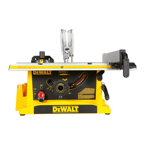
Summary of Contents for DeWalt DWE7470
- Page 1 DWE7470 10" (254 mm) Table Saw...
-
Page 2: Definitions: Safety Guidelines
• DO NOT USE THE MACHINE IN A DANGEROUS ENVIRONMENT. The use of power Definitions: Safety Guidelines tools in damp or wet locations or in rain can cause shock or electrocution. Keep your work The definitions below describe the level of severity for each signal word. Please read the area well-lit to avoid tripping or placing arms, hands, and fingers in danger. -
Page 3: Additional Safety Rules For Table Saws
• REDUCE THE RISK OF UNINTENTIONAL STARTING. Make sure that the switch is in • DO NOT PERFORM RIPPING, CROSSCUTTING OR ANY OTHER OPERATION the “OFF” position before plugging in the power cord. In the event of a power failure, move FREEHAND. -
Page 4: Specifications
• Freehand refers to cutting without the use of a miter gauge or rip fence or any the nearest authorized D WALT service center for repair. The riving knife must be in other means of guiding or holding the workpiece other than the operator’s hand. alignment with the saw blade and the anti-kickback assembly must stop a kickback WARNING: Never perform freehand cutting with this saw. - Page 5 Unpacking FEATURES (Fig. 3, 4) FIG. 1 Examine Figures 3 and 4 to become familiar with the saw and its various parts. The following WARNING: To reduce the risk of injury, DO sections on assembly and adjustments will refer to these terms and you must know what and NOT connect the machine to the power source where the parts are.
- Page 6 Cord Wrap (Fig. 6) FIGURE 3 A. Table H. Overload relay button Attach the cord wrap brackets (O) to rear of saw using the hardware supplied. Tighten securely. B. Miter gauge I. Blade height/bevel adjustment wheel FIG. 6 C. Blade J.
- Page 7 To Remove Throat Plate (Fig. 9) REMOVING THE RIVING KNIFE ASSEMBLY NOTE: The throat plate should be removed and the blade raised to its highest position before Using finger hole (W) on the plate, pull throat plate (X) up and forward to expose the inside of proceeding.
-
Page 8: Rip Fence
If marring the supporting work surface is a concern, the DWE7470 can be mounted to scrap 3. Push down the rip fence latch (G) to lock the rip fence in place. Ensure the fence is secure. - Page 9 On-Off Switch (Fig. 16) FIG. 17 WARNING: To reduce the risk of injury, be sure switch is in the OFF position before plugging machine in. FIG. 16 WARNING: ALWAYS lock the switch OFF when the saw is not in use. Remove the key (KK) and keep it in a safe place.
- Page 10 ADJUSTING THE 90° AND 45° POSITIVE STOPS (FIG. 3, 21, 22) FIG. 18 This saw has positive stops that will quickly position the saw blade at 90° and 45° to the table. Make adjustments only if necessary. 90° Stop 1. Raise the saw blade arbor to its maximum height by turning the blade height/bevel adjustment wheel (I) clockwise.
- Page 11 BLADE BEVEL POINTER (FIG. 23) If the blade is partial to left side: FIG. 23 1. When the blade is positioned at 90°, adjust the blade 1. Turn the right adjustment screw (RR) counterclockwise and adjust the left side adjustment bevel pointer to read 0°...
- Page 12 Saw Blades (Fig. 28) The riving knife provided with this saw is marked as follows (Fig. 30): 0.09" (2.3 mm) THICK RIVING KNIFE. ONLY USE FOR 10" (254 mm) Ø BLADE WITH WARNING: Riving knifes must be matched to saw blade dimensions in order to function 0.09"...
- Page 13 6. Never try to pull the workpiece back with the blade turning. Turn the switch off, allow the WARNING: Ripping or crosscutting may cause saw to tip over while operating. Make sure blade to stop, raise the anti-kickback teeth on each side of the riving knife if necessary and saw is securely mounted to a stable surface.
- Page 14 Bevel Ripping (Fig. 37) 3. Feed the workpiece through until the edge of the material reaches the front edge of the FIG. 37 saw table top. This operation is the same as ripping 4. Continue feeding the material using the push block (A12) until the cut is complete. except the bevel angle is set to an Push Block (Fig.
-
Page 15: Compound Mitering
Bevel Crosscutting (Fig. 37) FIG. 40 24" (610 mm) This operation is the same as crosscutting except that the bevel angle is set to an angle other than 0°. For proper hand position, refer to Figure 37. 3/4" (20 mm) WARNING: Before connecting the table saw to the power source or operating the saw, THE KERF always inspect the blade guard assembly and riving knife for proper alignment and clearance SHOULD BE... -
Page 16: Protecting The Environment
You can check the location of your nearest authorized service center by contacting your local D WALT office. Alternatively, a service center listing is included in the packaging of this product. SPECIFICATIONS DWE7470-B1 MAINTENANCE Voltage: 220-240 V ~ Frequency: 50/60 Hz...
Need help?
Do you have a question about the DWE7470 and is the answer not in the manual?
Questions and answers