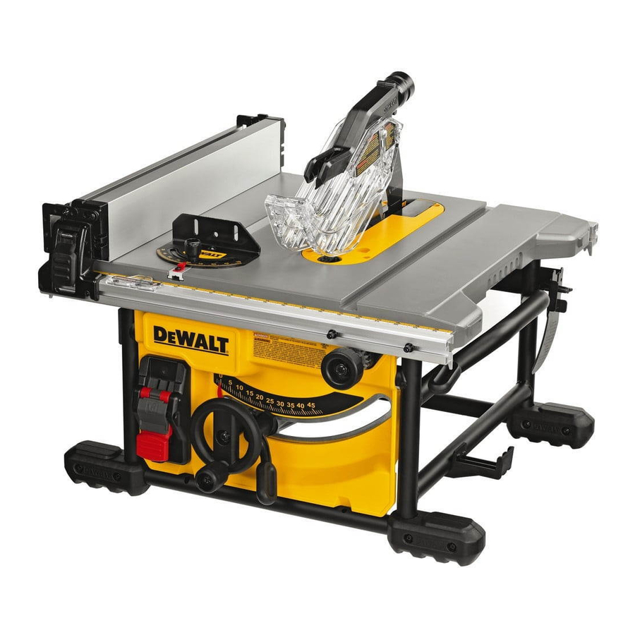
DeWalt DWE7485 Original Instructions Manual
Hide thumbs
Also See for DWE7485:
- User manual ,
- Original instructions manual (176 pages) ,
- Instruction manual (45 pages)
Table of Contents
Advertisement
Advertisement
Table of Contents

Subscribe to Our Youtube Channel
Summary of Contents for DeWalt DWE7485
- Page 1 DWE7485 Final page size: A5 (148mm x 210mm)
- Page 2 English (original instructions) Copyright D WALT...
- Page 3 Fig. A...
- Page 4 Fig. B Fig. C Fig. D...
- Page 5 Fig. E Fig. F Fig. G Fig. H Fig. I...
- Page 6 Fig. J Fig. K Fig. L Fig. M...
- Page 7 Fig. N Fig. O Fig. P Fig. Q...
-
Page 8: Technical Data
English TABLE SAW DWE7485 Congratulations! doing the job. This may significantly reduce the exposure level over the total working period. You have chosen a D WALT tool. Years of experience, thorough Identify additional safety measures to protect the product development and innovation make D... -
Page 9: Work Area Safety
*Date code 201811475B or later **Date code 201536 or later English NOTICE: Indicates a practice not related to influence of drugs, alcohol or medication. A moment personal injury which, if not avoided, may result in of inattention while operating power tools may result in serious personal injury. - Page 10 English f ) Keep cutting tools sharp and clean. Properly A moment of inattention or a slip could direct your hand maintained cutting tools with sharp cutting edges are less towards the saw blade and result in serious likely to bind and are easier to control. personal injury.
-
Page 11: Kickback Causes And Related Warnings
English cracked or broken teeth. Sharp and properly set saw thin workpiece may wedge under the rip fence and create a kickback. blades minimise binding, stalling and kickback. 3) Kickback Causes and Related Warnings 4) Table Saw Operating Procedure Warnings Kickback is a sudden reaction of the workpiece due to a pinched, a ) Turn off the table saw and disconnect the power jammed saw blade or misaligned line of cut in the workpiece with cord when removing the table insert, changing... -
Page 12: Residual Risks
English • Be sure all blade and flanges are clean and the larger face • Impairment of hearing. of the clamp washer is against the blade. Tighten the arbor • Risk of accidents caused by the uncovered parts of the rotating nut securely. -
Page 13: Package Contents
English Package Contents Rip fence Riving knife (non-through sawing) (Fig. C) Rip fence latch The package contains: Mitre gauge storage Narrow ripping fence/ 1 Partly assembled machine support extension Cable holder 1 Rip fence assembly Blade wrenches (stored DE7400 brackets mounting 1 Mitre fence position) holes... - Page 14 English 1. Raise the saw blade arbour to its maximum height by travel and insure the blade guard assembly clears the blade in turning the blade height adjustment wheel clockwise. 6 all operations. 2. Remove the throat plate 15 . Refer to Mounting the WARNING: Correct mounting and alignment of the blade Throat Plate.
-
Page 15: Blade Adjustment
English ADJUSTMENTS Parallel Adjustment (Fig. A, H, I) For optimum performance, the blade must be parallel to the Blade Adjustment rip fence. This adjustment has been made at the factory. To Blade Alignment (Parallel to Mitre Slot) (Fig. F) re-adjust: WARNING: Cut Hazard. Check the blade at 0˚ and 45˚ Position 1 Fence Alignment to make sure blade does not hit the throat plate, causing 1. -
Page 16: Body And Hand Position
English Bevel Stop And Pointer Adjustment (Fig. K) To reduce effects of increased vibration, make sure the environment is not too cold, the machine and accessory are well 1. Raise the blade fully by rotating the blade height maintained and the workpiece size is suitable for this machine. adjustment wheel ... -
Page 17: Compound Mitre
English To use the narrow ripping fence in the work support position, Bevel Cuts (Fig. A) rotate it from its stored position as shown in Figure M, and WARNING: Avoid bevel ripping on the beveling (left) side slide the pins into the lower sets of slots 42 ... -
Page 18: Maintenance
English • Ensure that the dust extraction hose in use is suitable for the application and material being cut. Ensure proper hose management. Lubrication (Fig. P) • A splitter accessory is available to connect both ports to a The motor and bearings require no additional lubrication. If single dust extractor. -
Page 19: Optional Accessories
English Optional Accessories WARNING: Since accessories, other than those offered by D WALT, have not been tested with this product, use of such accessories with this tool could be hazardous. To reduce the risk of injury, only D WALT recommended accessories should be used with this product. - Page 20 Belgique et WALT - Belgium BVBA Tel: NL 32 15 47 37 63 www.dewalt.be Luxembourg België en Luxemburg Egide Walschaertsstraat 16 Tel: FR 32 15 47 37 64 enduser.BE@SBDinc.com 2800 Mechelen Fax: 32 15 47 37 99 Danmark WALT (Stanley Black&Decker AS)


Need help?
Do you have a question about the DWE7485 and is the answer not in the manual?
Questions and answers