Hitachi H 45SR Technical Data And Service Manual
Hide thumbs
Also See for H 45SR:
- Handling instructions manual (21 pages) ,
- Handling instruction (28 pages)

Related Manuals for Hitachi H 45SR


Summary of Contents for Hitachi H 45SR
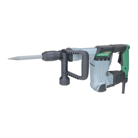
- Page 1 MODEL H 45SR POWER TOOLS TECHNICAL DATA HAMMER H 45SR SERVICE MANUAL LIST No. E464 May 2002 SPECIFICATIONS AND PARTS ARE SUBJECT TO CHANGE FOR IMPROVEMENT...
- Page 2 REMARK: Throughout this TECHNICAL DATA AND SERVICE MANUAL, a symbol(s) is(are) used in the place of company name(s) and model name(s) of our competitor(s). The symbol(s) utilized here is(are) as follows: Competitors Symbols Utilized Model Name Company Name HM0810 MAKITA...
-
Page 3: Table Of Contents
8-6. Tool Retainer ..........................12 8-7. Side Handle ..........................12 9. REPAIR GUIDE ..........................13 9-1. Precautions and Suggestions for Disassembly and Reassembly of the Main Body ..... 13 10. STANDARD REPAIR TIME (UNIT) SCHEDULES ..............18 Assembly Diagram for H 45SR... -
Page 4: Product Name
Hitachi Electric Hammer, Model H 45SR 2. MARKETING OBJECTIVE The Model H 45SR is an upgraded version of the current Model H 41SA, which features the use of Hitachi 17-mm hexagonal tools. The performance, durability and operability are greatly improved. With this competitive Model H 45SR, we aim to enhance the share of the Hitachi 17-mm hexagonal shank type hammers. -
Page 5: Selling Point Descriptions
Conventional mechanism for prevention of idle hammering is to open and close the air holes according to the movement of the striker. The Model H 45SR has air holes located at the position unaffected by the rebound of the striker at no load. The air holes are opened and closed by the movement of sleeve (A) provided around the cylinder that interlocks with the tool and the second hammer to prevent idle hammering. -
Page 6: Specifications
4-1-8. Original design vibration-absorbing handle (Vibration-absorbing is significantly improved) Hitachi's original design vibration-absorbing handle minimizes vibration through the rolling and compression of four cylindrical rubber cushions on inclined surfaces. The spring constant factor is as low as that of the Models H 45SB2, H 41SC, H 45MR, H 60KA, H 60MA and H 60MB, and the cushioning structure greatly reduces vibration. -
Page 7: Optional Accessories
5-1. Optional Accessories (1) Demolition work (1) Bull point Hexagonal shank bull point Round shank bull point Overall length Code No. Overall length Code No. 280 mm (11-1/32") 980752 280 mm (11-1/32") 981922 450 mm (17-23/32") 980753 450 mm (17-23/32") 981923 (2) Cutting, peeling, grooving and edging work (asphalt cutting, etc.) (1) Cutter... - Page 8 (6) Self-drilling anchor setting work (1) Anchor adaptor (for impact) Size No. Anchor size Code No. No. 30 W3/8 981929 982702 No. 40 W1/2 981930 (2) Turning handle 982703 Code No. 944573 N. 50 W5/8 981931 982704 (3) Drift key Code No.
-
Page 9: Comparisons With Similar Products
6. COMPARISONS WITH SIMILAR PRODUCTS 6-1. Specification Comparison Maker HITACHI Model name H 45SR H 41SA For Europe, Europe, Southeast Australia, Asia Europe, Southeast Australia Korea etc. Asia Australia Asia 1,050 1,050 1,050 Power input 12.5 Striking energy per stroke 8.53... -
Page 10: Full-Load Vibration Level Comparison
6-3. Full-load Vibration Level Comparison The graph shown in Fig. 2 illustrates the relationship between handle pressing force and handle vibration level in the Z direction. 126.0 HITACHI H 45SR HITACHI H 41SA 124.0 Normal pressing force range 122.0 120.0 118.0... -
Page 11: Precautions In Sales Promotion
7. PRECAUTIONS IN SALES PROMOTION In the interest of promoting the safest and most efficient use of the Model H 45SR Electric Hammer by all of our customers, it is very important that at the time of sale the salesperson carefully ensures that the buyer seriously recognizes the importance of the contents of the Handling Instructions, and fully understands the meaning of the precautions listed on the Caution Plate attached to each tool. -
Page 12: O-Ring Replacement
7-4. O-Ring Replacement The O-rings (mounted on the striker and piston) are extremely important to ensure adequate sealing of the air pressure. Although the O-rings are made of special rubber to give them a long service life, they do nonetheless become worn, and should be replaced by new ones periodically depending on frequency of use of the tool. -
Page 13: Idling-Proof Mechanism
(A) as shown in Fig. 6 then the cushion (damper (A)) provided between hammer holder (A) and the front cover absorbs the striking force of the second hammer. Thus the durability of the Model H 45SR is increased greatly because the second hammer does not strike the tool retainer directly. -
Page 14: Sealed And Dustproof Construction
8-5. Vibration Absorbing Construction Hitachi original, innovative units which absorb vibration are installed between the switch handle and the cylinder crank case and between the switch handle and the housing. As a result, the amount of vibration transmitted from the main body to the arms of the operator is considerably less in comparison with conventional hammers. -
Page 15: Tool Retainer
8-6. Tool Retainer The Model H 45SR is equipped with a slide-type tool retainer. Tools can be attached and detached just by pulling grip (A). While pulling grip (A) in direction, insert the tool in the hole of the front cap (Fig. 9). Adjust the hexagonal shank position by turning the tool and push it in to the end. -
Page 16: Repair Guide
9. REPAIR GUIDE 9-1. Precautions and Suggestions for Disassembly and Reassembly of the Main Body The numbers in [Bold] correspond to the item numbers in the Parts List and exploded assembly diagrams. 9-1-1. Disassembly Retainer disassembly (See Figs. 11 and 12.) Pull Grip (A) [4] fully in the arrow direction as shown in Fig. - Page 17 First gear and crank shaft disassembly Remove the grease from the Connecting Rod [32] side and the First Gear [51] side of the Cylinder Crank Case [46]. Remove the two Seal Lock Hex. Socket Flat Hd. Bolts M5 x 12 [42] fixing Bearing Cover (A) [43]. Then place the Connecting Rod [32] side of the Cylinder Crank Case [46] downward on a workbench and apply pressure on the end surface of the Crank Shaft [40] with a hand press to remove the First Gear [51] and the Crank Shaft [40] (Fig.
- Page 18 Apply Hitachi Motor Grease No. 29 to the Needle Bearing (M661) [52], the pinion portion of the Armature [68] and the Steel Ball D7.94 [7]. Seal 20 g of the Hitachi Motor Grease No. 29 into the Cylinder Crank Case [46] (the First Gear [51] side).
- Page 19 Oil seals Be very careful not to damage the O-ring (1AS-50) [14] on the Front Cover Ass'y [10], O-ring (S-34) [13] in the Front Cover Ass'y [10], O-ring (S-25) [17] in Hammer Holder (A) [16], O-ring (1AS-60) [38] in the Crank Cover [36], O-rings [25] in the Striker [24] and in the Piston [31], and Oil Seal [45] in the Cylinder Crank Case [46].
- Page 20 9-1-5. Internal wiring Wiring diagram for products with noise suppressor Stator Connector Brown Plug Connector Noise suppressor Armature Blue Pillar terminal Stator Fig. 17 Wiring diagram for products without noise suppressor Stator Black white Plug Armature Blue black Connector Stator Fig.
-
Page 21: Standard Repair Time (Unit) Schedules
10. STANDARD REPAIR TIME (UNIT) SCHEDULES Variable 60 min. MODEL Fixed Work Flow H 45SR Housing Ass'y Stator Ass'y Gear Cover Ass'y Switch (B) Needle Bearing Cord Tail Cover Armature Ass'y Ball Bearing (6201DD) Crank Cover Ball Bearing O-ring (608VV) - Page 22 LIST NO. E464 ELECTRIC TOOL PARTS LIST HAMMER 2002 • • Model H 45SR (E1)
- Page 23 PARTS H 45SR ITEM CODE NO. DESCRIPTION REMARKS USED 320-844 FRONT CAP 320-846 RETAINING RING D28 320-847 SLEEVE (C) 320-845 GRIP (A) 320-848 BALL HOLDER 320-849 SPRING (A) 944-941 STEEL BALL D7.94 320-850 RETAINING RING D35 320-851 GRIP (B) 320-915 FRONT COVER ASS’Y...
- Page 24 PARTS H 45SR ITEM CODE NO. DESCRIPTION REMARKS USED 939-299 NEEDLE BEARING (M661) 320-841 GEAR COVER ASS’Y INCLUD.52 317-107 BOLT M8 317-106 HANDLE HOLDER (B) 317-105 HANDLE HOLDER (A) 320-635 BAND 317-108 GRIP 317-103 SIDE HANDLE ASS’Y INCLUD.54-58 935-829 BRUSH CAP...
-
Page 25: Standard Accessories
H 45SR PARTS ITEM CODE NO. DESCRIPTION REMARKS USED 960-266 CORD CLIP 949-423 WASHER M4 (10 PCS.) FOR AUS,SAF,YEN,EUROPE 980-063 TERMINAL FOR CORD 953-327 CORD ARMOR D8.8 938-051 CORD ARMOR D10.1 500-394Z CORD (CORD ARMOR D10.1) 500-424Z CORD (CORD ARMOR D8.8) FOR SIN,MAL,SRI 500-390Z CORD (CORD ARMOR D8.8) FOR KOR,SAF,YEN,EUROPE...
Need help?
Do you have a question about the H 45SR and is the answer not in the manual?
Questions and answers