Table of Contents
Advertisement
Quick Links
In the interests of user-safety (Required by safety regulations in some countries) the set should be restored to its
original condition and only parts identical to those specified should be used.
» ELECTRICAL SPECIFICATIONS ................................. 1
» IMPORTANT SERVICE SAFETY PRECAUTION ........ 2
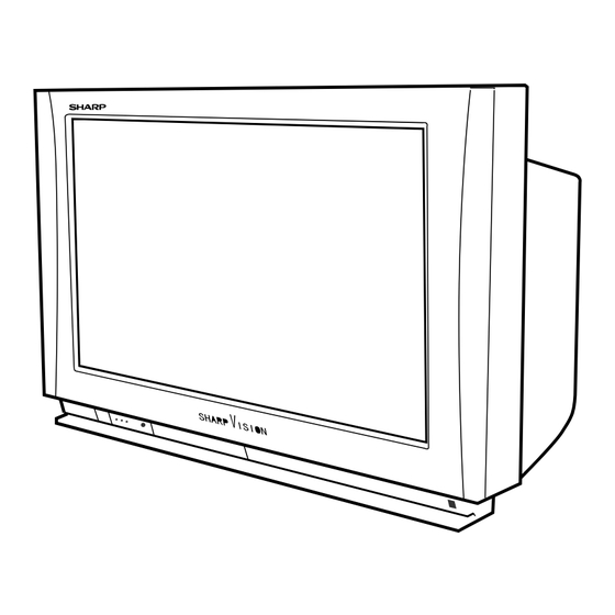
» LOCATION OF USER'S CONTROL ............................. 4
» DIMENSIONS ............................................................... 6
» REMOVING THE MAJOR PARTS ................................ 7
» DRESSING THE LEADS ............................................ 10
» INSTALLATION AND SERVICE INSTRUCTIONS ...... 11
POWER INPUT ...................................................... 120V AC 60 Hz
POWER RATING .................................................................. 205 W
PICTURE SIZE .......................................... 3,160 cm
CONVERGENCE ............................................................. Magnetic
SWEEP DEFLECTION .................................................... Magnetic
FOCUS ................................................ Hi-Bi-Potential Electrostatic
INTERMEDIATE FREQUENCIES
Picture IF Carrier Frequency ...................................... 45.75 MHz
Sound IF Carrier Frequency ....................................... 41.25 MHz
Color Sub-Carrier Frequency ..................................... 42.17 MHz
AUDIO POWER
OUTPUT RATING .... 24 W (12 W + 12 W)(at 10% distortion and
SPEAKER
SIZE ................................ 10 cm (BOX)(2 pcs.), Tweeter (2 pcs.)
VOICE COIL IMPEDANCE ................................ 6 ohm at 400 Hz
ANTENNA INPUT IMPEDANCE
VHF/UHF ..................................................... 75 ohm Unbalanced
TUNING RANGES
VHF-Channels ............................................................... 2 thru 13
UHF-Channels ............................................................ 14 thru 69
CATV Channels ........................................................... 1 thru 125
SHARP CORPORATION
SERVICE MANUAL
MODEL
CONTENTS
Page
ELECTRICAL SPECIFICATIONS
2
(489 sq inch)
(Nominal)
Dual CH Operate)
(EIA, Channel Plan U.S.A.)
1
COLOR TELEVISION
Chassis No. D00A
34N-WF5H
» ELECTRICAL ADJUSTMENT .................................... 12
» CHASSIS LAYOUT ..................................................... 26
» BLOCK DIAGRAM ..................................................... 28
» SCHEMATIC DIAGRAMS .......................................... 32
» PRINTED WIRING BOARD ASSEMBLIES ................ 65
» REPLACEMENT PARTS LIST .................................... 76
» PACKING OF THE SET ............................................ 103
VIDEO INPUT ............. (INPUT 1, 2, 3, 4) Composite
Input Jack :Pin-jack × 1
Input Level :1 Vp-p/75 ohm/Negative Sync
S-VIDEO INPUT .......... (INPUT 1, 2, 3) Y/C
Y :1 Vp-p/75 ohm/Negative Sync
C :0.286 Vp-p/75 ohm
COMPONENT INPUT ... (INPUT 4, 5) Component (Y, P
Input Jack :Pin-jack × 3 (INPUT 4),
Input Signal : 480I, 480P, 1080I
Y
P
, P
B
HD INPUT ................... (INPUT 3) R, G, B, H.V/R, G, B
Input Jack :D-Sub 15pin × 1
Input Signal : 480P , 1080I
RGB
AUDIO INPUT ............. (INPUT 1, 2, 3, 4, 5)
Input Jack :Pin-jack × 2
LINE OUTPUT ............. Input Jack :Pin-jack × 2
Specifications are subject to change without
prior notice.
This document has been published to be used for after
sales service only.
The contents are subject to change without notice.
34N-WF5H
S40Z134N-WF5H
Page
, P
)
B
R
BNC × 3 (INPUT 5)
:1 Vp-p/75 ohm/Negative Sync
:0.525 Vp-p/75 ohm
R
(75% Saturation Level)
:0.7 Vp-p/75 ohm/No Sync
0.5 Vrms/22k ohm or over
0.89 Vrms (Max)/2.2k ohm or
less/Veriable
Advertisement
Table of Contents

Related Manuals for Sharp 34N-WF5H


Summary of Contents for Sharp 34N-WF5H
-
Page 1: Table Of Contents
34N-WF5H SERVICE MANUAL S40Z134N-WF5H COLOR TELEVISION Chassis No. D00A 34N-WF5H MODEL In the interests of user-safety (Required by safety regulations in some countries) the set should be restored to its original condition and only parts identical to those specified should be used. -
Page 2: Important Service Safety Precaution
34N-WF5H IMPORTANT SERVICE SAFETY PRECAUTION Service work should be performed only by qualified service technicians who are thoroughly familiar with all safety checks and the servicing guidelines which follow: WARNING X-RADIATION AND HIGH VOLTAGE LIMITS 1. For continued safety, no modification of any circuit 1. -
Page 3: Safety Notice
34N-WF5H IMPORTANT SERVICE SAFETY PRECAUTION (Continued) • Connect the resistor connection to all exposed metal BEFORE RETURNING THE RECEIVER parts having a return to the chassis (antenna, metal (Fire & Shock Hazard) cabinet, screw heads, knobs and control shafts, escutcheon and etc.) and measure the AC voltage Before returning the receiver to the user, perform drop across the resistor. -
Page 4: Location Of User's Control
34N-WF5H LOCATION OF USER'S CONTROL Front control section POWER Press → → Press again Off. POWER VIEW TIMER HD TV (Stand-by: RED (RED) (GREEN) ON: GREEN) SENSOR AREA FOR REMOTE CONTROL VOL(+)/(–) buttons (+) Increases sound INPUT button AUDIO L/R IN DOOR Selects Input No. - Page 5 DIRECT ACCESS INPUT 3 mode. Press 4 times → Switches to external video Accesses any channel by the keypad. DISPLAY button: Sharp DTV Decoder only INPUT 4 mode. ENT. FLASHBACK Press 5 times → Switches to external video CC (Closed Caption) INPUT 5 mode.
-
Page 6: Dimensions
34N-WF5H DIMENSIONS Top View Front View Side View [Units: mm (inches)]... -
Page 7: Removing The Major Parts
34N-WF5H REMOVING THE MAJOR PARTS 1. Remove the 13 lock screws off the rear cover. 2. Holding up the chassis frame, draw out the chassis about 5 cm (1. inch) first, disconnect the speaker leads from the signal Unit, and pull out the chassis all the way. - Page 8 34N-WF5H Servicing precautions 1. Protector Operation This model is provided with five protector circuits. Below discussed are the behaviors and indications of these circuits. (Note: In some cases, the LED flashing cycle and possible trouble spot may be inconsistent.) 1 Over-current Protector Circuit: A rush current into the flyback transformer is detected.
- Page 9 34N-WF5H 3. Self-diagnostic Function (Protector Circuit Operation) This model is equipped with five protector circuits. Shown below are the detections of the protector circuits and possible trouble spots (outlined).
-
Page 10: Dressing The Leads
34N-WF5H DRESSING THE LEADS Insert GS and dress the leads with no Insert EW Insert NS. slack. Fold back and Speaker boxe:RSP-Z0109CEZZ x2 Insert EW ×2 bundle the leads. Place the speaker boxes in position and tighten the 4 screws. -
Page 11: Installation And Service Instructions
34N-WF5H INSTALLATION AND SERVICE INSTRUCTIONS Note: (1) When performing any adjustments to resistor controls and transformers use non-metallic screwdrivers or TV alignment tools. (2) Before performing adjustments, the TV set must be on at least 15 minutes. HIGH VOLTAGE CHECK CIRCUIT PROTECTION The receiver is protected by a 5.0A fuse (F701),... -
Page 12: Electrical Adjustment
34N-WF5H ELECTRICAL ADJUSTMENT The TV set has been factory-adjusted to optimum condition. If by any chance an adjustment point gets out of spec or readjustment is needed after component part replacement, take the following steps. » Instruments required for servicing •... - Page 13 34N-WF5H 3) Address settings (selecting adjustment and setting items) 1 Using the numeric buttons (0 thru 9), type in an address from the highest digit (left) to the lowest digit (right) one by one. Each time a digit is buttoned in, the cursor moves to the next entry position.
-
Page 14: Adjustment Items
34N-WF5H Adjustment items Video-Related Adjustment Make the initial factory settings 2 first and then go to this adjustment. REFERENCE DATA DATA VARIABLE NTSC HD-IN (RGB) HD-IN (RGB) ITEM ADDRESS 1080I Input RANGE Signal Input 1080I Input 480P Input Picture 0~69... - Page 15 34N-WF5H AdjustingPoint Adjusting Conditions Adjusting Procedure VCO adjustment Signal: Good local channel 1. Receive the good local channel. (L205 and L255 on Adjusting point: 2. Connect the digital voltmeter to pins (28) and (29) Tuner Unit) L205 and L255 of JA connector (SC1401).
- Page 16 34N-WF5H Modulator Settings Adjusting Adjusting Point Adjusting Procedure (Leader LMS237) Conditions Stereo separation Adjusting point: 1. Internal modulation: 1. Connect the oscilloscope probe adjustment R329, R331 400 Hz to (TP301) pin (7) of IC301. (R329, R331, R301 Measuring terminal: 2. Monaural: 2.
- Page 17 34N-WF5H AdjustingPoint Adjusting Conditions Adjusting Procedure 3D Y/C separation Signal: NTSC standard half 1. Receive the NTSC standard half color bar signal. level adjustment color bar signal 2. Connect the oscilloscope probe between pin (8) (R7000: Y/C3D Adjusting point: of SC3203 and GND.
- Page 18 34N-WF5H AdjustingPoint Adjusting Conditions Adjusting Procedure Brightness adjust- Signal: Good local channel 1. Make this adjustment after the deflection, white ment Adjusting point: balance, normal mask, purity, convergence and (R/C, JWS address Remote Control focus have all been completely adjusted.
- Page 19 34N-WF5H AdjustingPoint Adjusting Conditions Adjusting Procedure STRETCH-mode Signal: Monoscope pattern 1. Set the AV-mode to "STD-1". vertical linearity signal 2. Set the screen size to STRETCH-mode. adjustment Adjusting point: 3. Receive the monoscope pattern signal. (R/C, JWS address Remote Control 4.
- Page 20 34N-WF5H AdjustingPoint Adjusting Conditions Adjusting Procedure STRETCH-mode Adjusting point: 1. Take the same steps 1. and 2. for the STERTCH- corner distortion Remote Control mode vertical linearity adjustment. adjustment (JWS address 116) 2. Receive the crosshatch pattern signal. (R/C, JWS address Specification: 3.
- Page 21 34N-WF5H AdjustingPoint Adjusting Procedure Purity adjustment Visual adjustment procedure (1) Check the purity magnet assembly mounting position. (2) Receive the crosshatch pattern signal. (3) Adjust the raster tilt by turning the deflection yoke. (Align the projections at both ends of CRT’s X axis with the screen’s X axis.)
- Page 22 34N-WF5H AdjustingPoint Adjusting Procedure Convergence adjustment (1) Static convergence adjustment a) Receive the crosshatch pattern signal. b) Adjust the red and blue colors at the screen center by opening and closing or moving the 4-pole magnet. c) Adjust the green and magenta colors at the screen center using the 6- polemagnet in the same way.
- Page 23 34N-WF5H AdjustingPoint Adjusting Procedure White balance adjust- (1) Receive the monoscope pattern signal. Set the AV mode to "STD-1" and the ment quality-picture mode to "480P". (2) Using the R/C unit keys, enter the JWS address170. Set the data "1" (Y- Mute &...
- Page 24 34N-WF5H AdjustingPoint Adjusting Procedure Deflection distortion, 1. HD (component) signal input vertical and horizontal 1) Set the AV mode to "STD-1". position adjustments at 2) Feed the monoscope pattern (1080I) signal through the INPUT5 BNC various signal inputs terminal. 3) Referring to Table-2, take the adjustment point step No.15 thru 22.
- Page 25 34N-WF5H AdjustingPoint Adjusting Procedure White balance adjust- 1. Set the AV mode to "STD-1". Feed the monoscope pattern signal (1080I) ment at HD-IN through the INPUT3/HD INPUT (D-sub 15-pin) terminal. Select and receive (1080I RGB) signal input the INPUT3 HD-IN signal.
-
Page 26: Chassis Layout
34N-WF5H CHASSIS LAYOUT... -
Page 27: Block Diagram
34N-WF5H BLOCK DIAGRAM-1/2... - Page 28 34N-WF5H BLOCK DIAGRAM-2/2...
-
Page 29: Description Of Schematic Diagram
34N-WF5H DESCRIPTION OF SCHEMATIC DIAGRAM WAVEFORM MEASUREMENT CONDITIONS: NOTES: 1. Photographs taken on a standard gated color bar 1. The unit of resistance "ohm" is omitted. (K=k Ω =1000 Ω , M=M Ω ) signal, the tint setting adjusted for proper color. The wave shapes at the red, green and blue cathodes of 2. - Page 30 34N-WF5H SCHEMATIC DIAGRAM: CRT Unit...
-
Page 31: Schematic Diagrams
34N-WF5H SCHEMATIC DIAGRAM: SIGNAL Unit-1/5... - Page 32 34N-WF5H SCHEMATIC DIAGRAM: SIGNAL Unit-2/5...
- Page 33 34N-WF5H SCHEMATIC DIAGRAM: SIGNAL Unit-3/5...
- Page 34 34N-WF5H SCHEMATIC DIAGRAM: SIGNAL Unit-4/5...
- Page 35 34N-WF5H SCHEMATIC DIAGRAM: SIGNAL Unit-5/5...
- Page 36 34N-WF5H SCHEMATIC DIAGRAM: POWER Unit...
- Page 37 34N-WF5H SCHEMATIC DIAGRAM: TUNER Unit-1/2...
- Page 38 34N-WF5H SCHEMATIC DIAGRAM: TUNER Unit-2/2...
- Page 39 34N-WF5H SCHEMATIC DIAGRAM: YUV SW Unit...
- Page 40 34N-WF5H SCHEMATIC DIAGRAM: MICOM Unit...
- Page 41 34N-WF5H SCHEMATIC DIAGRAM: ZOOM Unit-1/3...
- Page 42 34N-WF5H SCHEMATIC DIAGRAM: ZOOM Unit-2/3...
- Page 43 34N-WF5H SCHEMATIC DIAGRAM: ZOOM Unit-3/3...
- Page 44 34N-WF5H SCHEMATIC DIAGRAM: Y/D 3D Unit...
- Page 45 34N-WF5H SCHEMATIC DIAGRAM: AC FILTER Unit AC F I LT E R...
- Page 46 34N-WF5H SCHEMATIC DIAGRAM: CONTROL Unit (DUNTKA098DE01)
- Page 47 34N-WF5H SCHEMATIC DIAGRAM: TERMINAL Unit...
-
Page 48: Printed Wiring Board Assemblies
34N-WF5H PRINTED WIRING BOARD ASSEMBLIES PWB-B: CRT Unit (Wiring Side) PWB-G: TERMINAL Unit (Wiring Side) - Page 49 34N-WF5H PWB-A: SIGNAL Unit (A Side)
- Page 50 34N-WF5H PWB-A: SIGNAL Unit (B Side)
- Page 51 34N-WF5H PWB-K: ZOOM Unit (A Side) PWB-K: ZOOM Unit (B Side)
- Page 52 34N-WF5H PWB-C: POWER Unit (Wiring Side)
- Page 53 34N-WF5H PWB-E: TUNER Unit (A Side) PWB-J: MICOM Unit (A Side)
- Page 54 34N-WF5H PWB-E: TUNER Unit (B Side) PWB-J: MICOM Unit (B Side)
- Page 55 34N-WF5H PWB-L: Y/C 3D Unit (A Side) PWB-L: Y/C 3D Unit (B Side)
- Page 56 34N-WF5H PWB-D: AC FILTER Unit (Wiring Side)
- Page 57 34N-WF5H PWB-H: YUV SW Unit (A Side) PWB-H: YUV SW Unit (B Side)
- Page 58 34N-WF5H PWB-F: CONTROL Unit (Wiring Side)
-
Page 59: Replacement Parts List
IC2501 VHiTA1287F+-1 J TA1287F (EL) in USA: Contact your nearest SHARP Parts Distributor to order. IC3102 VHiBR2416E2-1 J BR24C16F For location of SHARP Parts Distributor, Please call Toll- IC3151 VHiZ86130S+-1 J Z8613012SSC Free; 1-800-BE-SHARP IC3205 VHiS81350HG-1 J S-81350HG IC3206 VHiS81350HG-1... - Page 60 34N-WF5H Ref. No. Part No. Description Code Ref. No. Part No. Description Code PWB-A: DUNTKA096DE01 D1837 VHDHSU119//-1 J Diode D1838 RH-EX0734CEZZ J Zener Diode, 12V SIGNAL UNIT (Continued) D1839 RH-EX0734CEZZ J Zener Diode, 12V D1840 RH-EX0734CEZZ J Zener Diode, 12V...
- Page 61 34N-WF5H Ref. No. Part No. Description Code Ref. No. Part No. Description Code PWB-A: DUNTKA096DE01 C1399 VCEAEA1HW105M J 1.0 C1426 VCKYCY1HB103K J 0.01 Ceramic SIGNAL UNIT (Continued) C1430 VCEAEA1HW105M J 1.0 C1431 VCEAEA1HW105M J 1.0 C458 VCEA0A1CW107M J 100 C1432 VCEAEA1HW105M J 1.0...
- Page 62 34N-WF5H Ref. No. Part No. Description Code Ref. No. Part No. Description Code PWB-A: DUNTKA096DE01 C5838 VCEAEA1CW106M J 10 C5839 VCEAEA1CW106M J 10 SIGNAL UNIT (Continued) C5840 VCEA0A1CW107M J 100 C5849 VCEA0A1CW227M J 220 C2505 VCKYCY1CB104K J 0.1 Ceramic C5850 VCEA0A1CW476M J 47 C2506 VCKYCY1CB104K J 0.1...
- Page 63 34N-WF5H Ref. No. Part No. Description Code Ref. No. Part No. Description Code PWB-A: DUNTKA096DE01 R1217 VRS-CY1JF000J 1/16W M-Ox. R1301 VRS-CY1JF101J J 100 1/16W M-Ox. SIGNAL UNIT (Continued) R1302 VRS-CY1JF101J J 100 1/16W M-Ox. R1303 VRS-CY1JF101J J 100 1/16W M-Ox.
- Page 64 34N-WF5H Ref. No. Part No. Description Code Ref. No. Part No. Description Code PWB-A: DUNTKA096DE01 R1964 VRS-CY1JF101J J 100 1/16W M-Ox. R1965 VRS-CY1JF101J J 100 1/16W M-Ox. SIGNAL UNIT (Continued) R1969 VRS-CY1JF333J J 33k 1/16W M-Ox. R1970 VRS-CY1JF153J J 15k 1/16W M-Ox.
- Page 65 34N-WF5H Ref. No. Part No. Description Code Ref. No. Part No. Description Code PWB-A: DUNTKA096DE01 R5821 VRS-CY1JF102J J 1.0k 1/16W M-Ox. R5822 VRS-CY1JF101J J 100 1/16W M-Ox. SIGNAL UNIT (Continued) R5823 VRS-CY1JF101J J 100 1/16W M-Ox. R5824 VRS-CY1JF101J J 100 1/16W M-Ox.
- Page 66 34N-WF5H Ref. No. Part No. Description Code Ref. No. Part No. Description Code PWB-A: DUNTKA096DE01 P3921 QPLGN0841CEZZ J Plug, 8-pin (SH) P5805 QPLGN1041CEZZ J Plug, 10-pin (RE) SIGNAL UNIT (Continued) P9801 QPLGN0678GEZZ J Plug, 6-pin (RD) SC1401 QSOCZ3041CEZZ J Socket, 30-pin (JA) R7330 VRS-CY1JF561J J 560 1/16W M-Ox.
-
Page 67: Crt Unit
34N-WF5H Ref. No. Part No. Description Code Ref. No. Part No. Description Code PWB-B: DUNTKA100DE01 C5411 VCKYPA1HF103Z J 0.01 Ceramic C5412 VCEA0A1CW476M J 47 CRT UNIT C5413 VCEA0A1CW476M J 47 C5414 VCEA0A2CW106M J 10 160V EL. INTEGRATED CIRCUITS C5415 VCEA0A2AW106M J 10 100V EL. - Page 68 34N-WF5H Ref. No. Part No. Description Code Ref. No. Part No. Description Code PWB-B: DUNTKA100DE01 PWB-C: DUNTKA140DE01 CRT UNIT (Continued) POWER UNIT INTEGRATED CIRCUITS P857 QTiPM0083CEZZ J Tip (K857) P861 QPLGN0878GEZZ J Plug, 8-pin (CJ) IC550 VHiLA7841//-1 J LA7841 P862...
- Page 69 34N-WF5H Ref. No. Part No. Description Code Ref. No. Part No. Description Code PWB-C: DUNTKA140DE01 C661 VCFPVC3DA242H J 2400p 1.8kV M-Poly. C672 VCFPGU2EC473J J 0.047 250V M-Poly. POWER UNIT (Continued) C674 VCFPGU2EC304J J 0.3 250V M-Poly. C680 RC-QZA223TAYJ J 0.022 50V...
- Page 70 34N-WF5H Ref. No. Part No. Description Code Ref. No. Part No. Description Code PWB-C: DUNTKA140DE01 R742 VRD-RA2HD470J J 47 1/2W Carbon R743 VRD-RA2EE102J J 1.0k 1/4W Carbon POWER UNIT (Continued) R752 VRD-RA2HD823J J 82k 1/2W Carbon R753 VRN-VV3ABR10J J 0.1 M-Film å...
- Page 71 34N-WF5H Ref. No. Part No. Description Code Ref. No. Part No. Description Code PWB-D: DUNTKA116DE01 PWB-C: DUNTKA140DE01 AC FILTER UNIT POWER UNIT (Continued) TRANSISTOR LHLDW1142CEZZ J Holder LX-BZ0086TAFD J Screw Q3770 VS2SC3198-Y-1 J 2SC3198(Y) LX-BZ3049GEFD J Screw DIODES LX-BZ3100CEFD J Screw...
- Page 72 34N-WF5H Ref. No. Part No. Description Code Ref. No. Part No. Description Code PWB-E: DUNTKA097DE01 L252 VPACK220J0000 J Peaking 22µH L254 VPACK150J0000 J Peaking 15µH TUNER UNIT L255 RCiLi0633CEZZ J VCO Coil L257 VP-OF1R0K0000 J Peaking 1µH TUNER L4801 VPACK560J0000 J Peaking 56µH...
- Page 73 34N-WF5H Ref. No. Part No. Description Code Ref. No. Part No. Description Code PWB-E: DUNTKA097DE01 C3819 VCKYCY1HB822K J 8200p 50V Ceramic C3820 VCKYCY1HB332K J 3300p 50V Ceramic TUNER UNIT (Continued) C3821 VCKYCY1HB332K J 3300p 50V Ceramic C3822 VCEAEA1CW106M J 10 C311 VCE9GA1HW475M J 4.7...
- Page 74 34N-WF5H Ref. No. Part No. Description Code Ref. No. Part No. Description Code PWB-E: DUNTKA097DE01 R427 VRS-CY1JF684J J 680k 1/16W M-Ox. R428 VRS-CY1JF122J J 1.2k 1/16W M-Ox. TUNER UNIT (Continued) R429 VRS-CY1JF223J J 22k 1/16W M-Ox. R430 VRS-CY1JF153J J 15k 1/16W M-Ox.
-
Page 75: Control Unit
34N-WF5H Ref. No. Part No. Description Code Ref. No. Part No. Description Code PWB-E: DUNTKA097DE01 PWB-F: DUNTKA098WEK0 TUNER UNIT (Continued) CONTROL UNIT TRANSISTORS R4818 VRS-CY1JF823J J 82k 1/16W M-Ox. R4820 VRS-CY1JF681J J 680 1/16W M-Ox. Q171 VS2SA1275Y/-1 J 2SA1275Y R4821 VRS-CY1JF102J J 1.0k 1/16W M-Ox. -
Page 76: Terminal Unit
34N-WF5H Ref. No. Part No. Description Code Ref. No. Part No. Description Code PWB-F: DUNTKA098WEK0 PWB-H: DUNTKA162DE01 CONTROL UNIT (Continued) YUV SW UNIT INTEGRATED CIRCUITS S152 QSW-K0091GEZZ J Switch, INPUT S153 QSW-K0091GEZZ J Switch, CH-DOWN IC4401 VHiM52055FP-1 J M52055FP S154... - Page 77 34N-WF5H Ref. No. Part No. Description Code Ref. No. Part No. Description Code PWB-H: DUNTKA162DE01 PWB-J: DUNTKA163DE01 YUV SW UNIT (Continued) MICOM UNIT INTEGRATED CIRCUITS R4412 VRS-CY1JF102J J 1.0k 1/16W M-Ox. R4413 VRS-CY1JF272J J 2.7k 1/16W M-Ox. IC3501 RH-iX3380CEN1 J M306V0EEFPA1 çå...
- Page 78 34N-WF5H Ref. No. Part No. Description Code Ref. No. Part No. Description Code PWB-J: DUNTKA163DE01 PWB-K: DUNTK9950DE02 MICOM UNIT (Continued) ZOOM UNIT INTEGRATED CIRCUITS R3543 VRS-CY1JF101J J 100 1/16W M-Ox. R3544 VRS-CY1JF562J J 5.6k 1/16W M-Ox. IC2201 VHiTC90A45F-1 J TC90A45F R3545 VRS-CY1JF101J J 100 1/16W M-Ox.
- Page 79 34N-WF5H Ref. No. Part No. Description Code Ref. No. Part No. Description Code C5504 VCEAEA1HW225M J 2.2 PWB-K: DUNTK9950DE02 C5505 VCCCCY1HH101J J 100p 50V Ceramic ZOOM UNIT (Continued) C5507 VCCCCY1HH101J J 100p 50V Ceramic C5508 VCEAEA1HW225M J 2.2 L2206 VPAWM220J4R0N J Peaking 22µH...
- Page 80 34N-WF5H Ref. No. Part No. Description Code Ref. No. Part No. Description Code PWB-K: DUNTK9950DE02 R2425 VRS-CY1JF271J J 270 1/16W M-Ox. R2426 VRS-CY1JF103J J 10k 1/16W M-Ox. ZOOM UNIT (Continued) R2427 VRS-CY1JF562J J 5.6k 1/16W M-Ox. R2428 VRS-CY1JF103J J 10k 1/16W M-Ox.
- Page 81 34N-WF5H Ref. No. Part No. Description Code Ref. No. Part No. Description Code PWB-K: DUNTK9950DE02 FB5661 RBLN-0064TAZZ J Ferrite Bead FB5666 RBLN-0061TAZZ J Ferrite Bead ZOOM UNIT (Continued) FB5667 RBLN-0064TAZZ J Ferrite Bead FB5689 RBLN-0061TAZZ J Ferrite Bead R5610 VRS-CY1JF102J J 1.0k 1/16W M-Ox.
- Page 82 34N-WF5H Ref. No. Part No. Description Code Ref. No. Part No. Description Code PWB-L: DUNTK9890DE05 C7038 VCCCCY1HH270J J 27p Ceramic C7039 VCKYCY1HB103K J 0.01 Ceramic Y/C 3D UNIT C7041 VCCCCY1HH3R0C J 3.0p Ceramic C7042 VCCCCY1HH120J J 12p Ceramic INTEGRATED CIRCUITS...
-
Page 83: Cabinet Parts
– Front Cabinet — R7087 VRS-CY1JF000J 1/16W M-Ox. GCOVA1849CESA J LED Decoration, R/C Cover AG GDORF2049CEKA J Door MISCELLANEOUS PARTS HBDGD3122CESA J Badge, "SHARP" FB7050 RBLN-0061TAZZ J Ferrite Bead HiNDP4998CEKZ J Indication Plate, In Door FB7051 RBLN-0061TAZZ J Ferrite Bead... - Page 84 34N-WF5H CABINET PARTS LOCATION Ref. No. Part No. Description Code Ref. No. Part No. Description Code 1 1-1 1-13 1-12 1-11 1-11 1-11 1-11 1-18 1-10 1-10 1-14 1-14 1-21 1-21 1-15 1-15 1-16 1-17 1-17 1-11 1-11 1-19 1-10...
-
Page 85: Miscellaneous Parts
34N-WF5H Ref. No. Part No. Description Code Ref. No. Part No. Description Code MISCELLANEOUS PARTS SUPPLIED ACCESORRIES QACCD3065CESA J AC Cord TGAN-1548CEZZ J Guarantee Card å RCORF0096CEZZ J Ferrite Core TiNS-6919CEZZ J Operation Manual PSLDM9190CEZZ J Shield RRMCG1550CESA J Infrared R/C Unit... -
Page 86: Packing Of The Set
34N-WF5H Ref. No. Part No. Description Code Ref. No. Part No. Description Code PACKING OF THE SET Polyethylene Bag Operation Manual Guarantee Card RF Cable Batteries Polyethylene Mat Infrared R/C Unit Buffer Material FRONT Packing Case Use 22 staples to fix the packing case. - Page 87 Code Ref. No. Part No. Description Code COPYRIGHT © 2000 BY SHARP CORPORATION ALL RIGHTS RESERVED. No part of this publication may be reproduced, stored in a retrieval system, or transmitted in any form or by any means, electronic, mechanical, photocopying, recording, or otherwise, without prior written permission of the publisher.
Need help?
Do you have a question about the 34N-WF5H and is the answer not in the manual?
Questions and answers