Table of Contents
Advertisement
32U-S600
In the interests of user-safety (Required by safety regulations in some countries ) the set should be restored to its
original condition and only parts identical to those specified should be used.
» ELECTRICAL SPECIFICATIONS ......................................................................................................... 1
» IMPORTANT SERVICE SAFETY PRECAUTION ................................................................................. 2
» LOCATION OF USER'S CONTROL ..................................................................................................... 4
» INSTALLATION AND SERVICE INSTRUCTIONS ................................................................................ 6
» SERVICE ADJUSTMENT ................................................................................................................... 10
» CHASSIS LAYOUT ............................................................................................................................. 14
» BLOCK DIAGRAM .............................................................................................................................. 16
» SCHEMATIC DIAGRAMS ................................................................................................................... 18
» PRINTED WIRING BOARD ASSEMBLIES ........................................................................................ 38
» REPLACEMENT PARTS LIST ............................................................................................................ 45
» PACKING OF THE SET ...................................................................................................................... 59
POWER INPUT ..................................................... 120V AC 60 Hz
POWER RATING .................................................................. 152W
PICTURE SIZE ........................................... 3,073cm
CONVERGENCE ............................................................. Magnetic
SWEEP DEFLECTION .................................................... Magnetic
FOCUS ............................................... Hi-Bi-Potential Electrostatic
INTERMEDIATE FREQUENCIES
Picture IF Carrier Frequency ..................................... 45.75 MHz
Sound IF Carrier Frequency ...................................... 41.25 MHz
Color Sub-Carrier Frequency .................................... 42.17 MHz
AUDIO POWER
OUTPUT RATING .............. 3.0W + 3.0W (at 10% distortion and
SHARP CORPORATION
SERVICE MANUAL
32U-S710
MODELS
ELECTRICAL SPECIFICATIONS
2
(476sq inch)
(Nominal)
Dual CH Operate)
COLOR TELEVISION
Chassis No. GB-1
32U-S600
32U-S710
SPEAKER
SIZE ........................................................ 12 x 6 cm oval (2 pcs.)
VOICE COIL IMPEDANCE ............................... 8 ohm at 400 Hz
ANTENNA INPUT IMPEDANCE
VHF/UHF ..................................................... 75 ohm Unbalanced
TUNING RANGES
VHF-Channels ............................................................... 2 thru 13
UHF-Channels ............................................................ 14 thru 69
CATV Channels ........................................................... 1 thru 125
Specifications are subject to change without
prior notice.
This document has been published to be used for after
sales service only.
The contents are subject to change without notice.
32U-S600
32U-S710
S62K132U-S600
Page
(EIA, Channel Plan U.S.A.)
Advertisement
Table of Contents

Related Manuals for Sharp 32U-S600


Summary of Contents for Sharp 32U-S600
-
Page 1: Table Of Contents
32U-S600 32U-S710 SERVICE MANUAL S62K132U-S600 COLOR TELEVISION Chassis No. GB-1 32U-S600 32U-S600 32U-S710 32U-S710 MODELS In the interests of user-safety (Required by safety regulations in some countries ) the set should be restored to its original condition and only parts identical to those specified should be used. -
Page 2: Important Service Safety Precaution
32U-S600 32U-S710 IMPORTANT SERVICE SAFETY PRECAUTION Ë Service work should be performed only by qualified service technicians who are thoroughly familiar with all safety checks and the servicing guidelines which follow: WARNING X-RADIATION AND HIGH VOLTAGE LIMITS 1. For continued safety, no modification of any circuit 1. -
Page 3: 32U-S600
32U-S600 32U-S710 IMPORTANT SERVICE SAFETY PRECAUTION (Continued) • Connect the resistor connection to all exposed metal BEFORE RETURNING THE RECEIVER parts having a return to the chassis (antenna, metal (Fire & Shock Hazard) cabinet, screw heads, knobs and control shafts, escutcheon, etc.) and measure the AC voltage drop... -
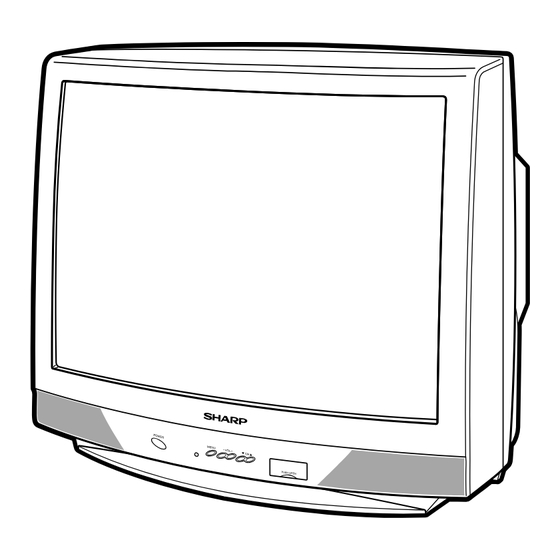
Page 4: Location Of User's Control
32U-S600 32U-S710 LOCATION OF USER'S CONTROL (32U-S600) Front Panel VIDEO IN 2 L-AUDIO-R POWER (INSIDE DOOR) Press → On. Press again → Off. CHANNEL UP/DOWN (') Selects next higher channel. (") Selects next lower channel. • Press both at the same time to MENU access the MAIN MENU screen. - Page 5 32U-S600 32U-S710 LOCATION OF USER'S CONTROL (32U-S710) Front Panel IN 2 VIDEO L-AUDIO-R (INSIDE DOOR) POWER CHANNEL UP/DOWN → Press ( ) Selects next higher → Press again Off. channel. ( ) Selects next lower SENSOR AREA FOR channel. REMOTE CONTROL •...
-
Page 6: Installation And Service Instructions
32U-S600 32U-S710 INSTALLATION AND SERVICE INSTRUCTIONS Note: (1) When performing any adjustments to resistor controls and transformers use non-metallic screwdrivers or TV alignment tools. (2) Before performing adjustments, the TV set must be on at least 15 minutes. CIRCUIT PROTECTION HIGH VOLTAGE CHECK The receiver is protected by a 4.0A fuse (F701),... -
Page 7: 32U-S600
32U-S600 32U-S710 For adjustments of this model, the bus data is converted to various analog signals by the D/A converter circuit. Note: There are still a few analog adjustments in this series such as focus and master screen voltage. Follow the steps below whenever the service adjustment is required. See "Table-B" to determine, if serv- ice adjustments are required. -
Page 8: Contents
32U-S600 32U-S710 DATA SERVICE ADJUSTMENT ITEM ADJUSTMENT CONTENTS NUMBER INITIAL VALUE RANGE PICTURE 0-15(00h-0Fh) TINT 0-127(00h-7Fh) COLOR 0-127(00h-7Fh) SUB-COLOR 0-31(00h-1Fh) Must be set to "10" BRIGHT 0-127(00h-7Fh) R CUT-OFF 64-255(40h-FFh) G CUT-OFF 64-255(40h-FFh) B CUT-OFF 64-255(40h-FFh) G DRIVE 0-127(00h-7Fh) B DRIVE... -
Page 9: 32U-S600
0-255(00h-FFh) Must be to "36" OPTION1 0-255(00h-FFh) Must be set to "F7" OPTION2 0-7(00h-07h) Must be set to "10" (32U-S600), "B9" (32U-S710) OPTION3 0-255(00h-FFh) Must be set to "0C" (32U-S600), "0E" (32U-S710) INPUT LEVEL 0-15(00h-0Fh) Must be set to "09"... -
Page 10: Service Adjustment
32U-S600 32U-S710 SERVICE ADJUSTMENT Sub-picture and Sub-Bright Adjustments RF AGC Adjustment 1. Receive the window pattern signal. 1. Receive a good local channel. • RF INPUT (TU51) 2. Enter the service mode and select the service 2. Get into service adjustment data "V01" and "V05"... -
Page 11: 32U-S600
2. Adjust the following data values as listed below. Vertical Phase Adjustment SERVICE ADJUST DATA(Hex) POSITION ITEM 32U-S600 32U-S710 1. Enter the service mode and select the service OPTION1 OPTION2 adjustment "D01". OPTION3 2. Adjust "D01" data value so that picture is centered. -
Page 12: 32U-S600
1. Input "SIGNAL 1" (TU51) and vary the "M04" bus data to get the minimun AC voltage to pin (39) of IC3001. MTS Level Adjustment (32U-S600) 2. Input "SIGNAL 2" (TU51) and vary the "M05" bus data 1. Receive the following composite signal. - Page 13 32U-S600 32U-S710 Ë P-IN-P ADJUSTMENT P-IN-P Y-LEVEL Adjustment 1. Receive a good local channel. 2. Enter the service mode and select the service adjustment "P01". 3. Adjust "P01" data value to obtain normal contrast level. P-IN-P TINT Adjustment 1. Receive a good local channel.
-
Page 14: Chassis Layout
32U-S600 32U-S710 MODEL 32U-S600 CHASSIS LAYOUT... - Page 15 32U-S600 32U-S710 MODEL 32U-S710 CHASSIS LAYOUT...
-
Page 16: Block Diagram
32U-S600 32U-S710 MODEL 32U-S600 BLOCK DIAGRAM... - Page 17 32U-S600 32U-S710 MODEL 32U-S710 BLOCK DIAGRAM...
-
Page 18: Schematic Diagrams
32U-S600 32U-S710 DESCRIPTION OF SCHEMATIC DIAGRAM WAVEFORM MEASUREMENT CONDITIONS: NOTES: 1. Photographs taken on a standard gated color bar 1. The unit of resistance "ohm" is omitted. Ω Ω Ω signal, the tint setting adjusted for proper color. The (K=k... - Page 19 32U-S600 32U-S710 MODEL 32U-S710 SCHEMATIC DIAGRAM: 2-TUNER Unit...
- Page 20 32U-S600 32U-S710 MODEL 32U-S600 SCHEMATIC DIAGRAM: MAIN-1 Unit...
- Page 21 32U-S600 32U-S710...
- Page 22 32U-S600 32U-S710 MODEL 32U-S600 SCHEMATIC DIAGRAM: MAIN-2 Unit...
- Page 23 32U-S600 32U-S710...
- Page 24 32U-S600 32U-S710 MODEL 32U-S710 SCHEMATIC DIAGRAM: MAIN-1 Unit...
- Page 25 32U-S600 32U-S710...
- Page 26 32U-S600 32U-S710 MODEL 32U-S710 SCHEMATIC DIAGRAM: MAIN-2 Unit...
- Page 27 32U-S600 32U-S710...
- Page 28 32U-S600 32U-S710 MODEL 32U-S600 SCHEMATIC DIAGRAM: CRT Unit...
- Page 29 32U-S600 32U-S710 MODEL 32U-S710 SCHEMATIC DIAGRAM: CRT Unit...
- Page 30 32U-S600 32U-S710 MODEL 32U-S600 SCHEMATIC DIAGRAM: AV Unit...
- Page 31 32U-S600 32U-S710...
- Page 32 32U-S600 32U-S710 MODEL 32U-S710 SCHEMATIC DIAGRAM: AV Unit...
- Page 33 32U-S600 32U-S710...
- Page 34 32U-S600 32U-S710 SCHEMATIC DIAGRAM: P-IN-P Unit...
- Page 35 32U-S600 32U-S710...
- Page 36 32U-S600 32U-S710 MODEL 32U-S600 SCHEMATIC DIAGRAM: MTS MODULE Unit...
- Page 37 32U-S600 32U-S710 MODEL 32U-S710 SCHEMATIC DIAGRAM: MTS MODULE Unit...
-
Page 38: Printed Wiring Board Assemblies
32U-S600 32U-S710 PRINTED WIRING BOARD ASSEMBLIES PWB-A: MAIN Unit (Wiring Side) - Page 39 32U-S600 32U-S710 PWB-A: MAIN Unit (Chip Parts Side)
- Page 40 32U-S600 32U-S710 PWB-C: AV Unit (Wiring Side) (Only for 32U-S600) PWB-C: AV Unit (Chip Parts Side) (Only for 32U-S600)
- Page 41 32U-S600 32U-S710 PWB-C: AV Unit (Wiring Side) (Only for 32U-S710) PWB-C: AV Unit (Chip Parts Side) (Only for 32U-S710)
- Page 42 32U-S600 32U-S710 PWB-R: P-IN-P Unit (Wiring Side) PWB-R: P-IN-P Unit (Chip Parts Side)
- Page 43 32U-S600 32U-S710 PWB-S: MTS MODULE Unit (Wiring Side) PWB-S: MTS MODULE Unit (Chip Parts Side)
- Page 44 32U-S600 32U-S710 PWB-B: CRT Unit (Wiring Side) PWB-K: 2-TUNER Unit (Wiring Side) (Only for 32U-S710)
-
Page 45: Replacement Parts List
3. PART NO. 4. DESCRIPTION QEARC3102MEZZ X Grounding Strap å in USA: Contact your nearest SHARP Parts Distributor to order. For location of SHARP Parts Distributor, Please call Toll-Free; 1- 800-BE-SHARP MARK: SPARE PARTS-DELIVERY SECTION MARK: X-RAY RELATED PARTS Ref. No. -
Page 46: Main Unit
32U-S600 32U-S710 Ref. No. Part No. Description Code Ref. No. Part No. Description Code PWB-A: DUNTKA526WED2(32U-S600) PWB-A: DUNTKA526WED7(32U-S710) VS2SC1623L61E Q2201 VS2PD601AR/-1 J 2PD601AR MAIN UNIT TUNER VS2SC1623L61E NOTE: THE PARTS HERES SHOWN ARE SUPPLIED AS AN Q2211 VS2PD601AR/-1 J 2PD601AR ASSEMBLY BUT NOT INDEPENDENTLY. - Page 47 32U-S600 32U-S710 Ref. No. Part No. Description Code Ref. No. Part No. Description Code PWB-A: DUNTKA526WED2(32U-S600) C370 VCEA0A1CW227M J 220 PWB-A: DUNTKA526WED7(32U-S710) C371 VCEA0A1EW108M J 1000 25V C372 VCEA0A1EW108M J 1000 25V MAIN UNIT(Continued) C373 VCKYCY1CF104Z J 0.1 Ceramic SF201 RFiLC0405CEZZ...
- Page 48 32U-S600 32U-S710 Ref. No. Part No. Description Code Ref. No. Part No. Description Code PWB-A: DUNTKA526WED2(32U-S600) C2044 VCQYTA1HM104J J 0.1 Mylar PWB-A: DUNTKA526WED7(32U-S710) C2060 VCKYCY1CF104Z J 0.1 Ceramic C2061 VCCCCY1HH101J J 100p 50V Ceramic MAIN UNIT(Continued) C2062 VCEA0A1AW107M J 100...
- Page 49 32U-S600 32U-S710 Ref. No. Part No. Description Code Ref. No. Part No. Description Code PWB-A: DUNTKA526WED2(32U-S600) R512 VRD-RA2BE683J J 68k 1/8W Carbon PWB-A: DUNTKA526WED7(32U-S710) R513 VRS-CY1JF273J J 27k 1/16W M-Ox. R514 VRS-CY1JF101J J 100 1/16W M-Ox. MAIN UNIT(Continued) R520 VRS-CY1JF184J J 180k 1/16W M-Ox.
- Page 50 32U-S600 32U-S710 Ref. No. Part No. Description Code Ref. No. Part No. Description Code PWB-A: DUNTKA526WED2(32U-S600) R913 VRS-CY1JF392J J 3.9k 1/16W M-Ox. PWB-A: DUNTKA526WED7(32U-S710) R914 VRS-CY1JF102J J 1k 1/16W M-Ox. (32U-S710) MAIN UNIT(Continued) R914 VRS-CY1JF182J J 1.8k 1/16W M-Ox. R713 VRS-RG2HC122J+ X 1.2k 1/2W...
- Page 51 J 18k 1/16W M-Ox. P705 QPLGN0160CEZZ J Plug, 1-pin(SG) R2502 VRS-CY1JF183J J 18k 1/16W M-Ox. P1301 QPLGN0561CEZZ J Plug, 5-pin(EJ) (32U-S600) AB R2503 VRS-CY1JF103J J 10k 1/16W M-Ox. P1301 QPLGN0661CEZZ J Plug, 6-pin(EJ) (32U-S710) AD R2504 VRS-CY1JF103J J 10k 1/16W M-Ox.
-
Page 52: Crt Unit
J Ferrite Bead (32U-S710) C1511 VCKYPA1HF103Z J 0.01 Ceramic P852 QPLGN0341CEZZ J Plug, 3-pin(PU) (32U-S710) AA (32U-S710) P854 QPLGN0441CEZZ J Plug (32U-S600) C1515 VCEA0A1EW476M J 47 P854 QPLGN0741CEZZ J Plug, 7-pin(YBN) (32U-S710) (32U-S710) C1516 VCEA0A1EW476M J 47 P860 QPLGN0541CEZZ J Plug, 5-pin(GBN) - Page 53 C1444 VCKYCY1HB472K J 4700p 50V Ceramic Q1406 VS2PB709AR/-1 J 2PB709AR (32U-S710) (32U-S710) C1445 VCKYCY1CF104Z J 0.1 Ceramic VS2SA812-M51E (32U-S600) Q1406 VS2SA812-M51E J 2SA812-M51 (32U-S600) AC C1445 VCKYCY1HF103Z J 0.01 Ceramic (32U-S710) VS2PB709AR/-1 C1446 VCCCCY1HH181J J 180p 50V Ceramic Q1407 VS2PD601AR/-1 J 2PD601AR C1447 VCKYCY1HF103Z J 0.01...
- Page 54 R1401 VRS-CY1JF101J J 100 1/16W M-Ox. MISCELLANEOUS PARTS (32U-S710) R1402 VRS-CY1JF681J J 680 1/16W M-Ox. P1904 QPLGN0541CEZZ J Plug, 5-pin(EJ) (32U-S600) AB R1403 VRS-CY1JF102J J 1k 1/16W M-Ox. P1904 QPLGN0641CEZZ J Plug, 6-pin(EJ) (32U-S710) AB (32U-S600) SC1901 QSOCN1598REZZ J Socket, 15-pin(VA) R1403 VRS-CY1JF332J J 3.3k 1/16W M-Ox.
- Page 55 32U-S600 32U-S710 Ref. No. Part No. Description Code Ref. No. Part No. Description Code PWB-K: DUNTKB223WEA0(32U-S710) PWB-R: DUNTKA533WEA0 2-TUNER UNIT P-IN-P UNIT TUNER INTEGRATED CIRCUIT NOTE: THE PARTS HERES SHOWN ARE SUPPLIED AS AN IC1801 VHiM65667FP-2 J M65667FP ASSEMBLY BUT NOT INDEPENDENTLY.
- Page 56 32U-S600 32U-S710 Ref. No. Part No. Description Code Ref. No. Part No. Description Code PWB-R: DUNTKA533WEA0 R1887 VRS-CY1JF123J J 12k 1/16W M-Ox. R1889 VRD-RA2BE101J J 100 1/8W Carbon P-IN-P UNIT(Continued) MISCELLANEOUS PARTS C1862 VCKYCY1CB104K J 0.1 Ceramic P1701 QPLGZ0810CEZZ J Plug, 8-pin...
- Page 57 32U-S600 32U-S710 Ref. No. Part No. Description Code Ref. No. Part No. Description Code PWB-S: DUNTKB224WEA2(32U-600) C3539 VCFYFA1HA334J J 0.33 Mylar PWB-S: DUNTKB224WEA1(32U-710) (32U-S710) C3540 VCEA0A1HW105M J 1 MTS MODULE UNIT (32U-S710) INTEGRATED CIRCUITS C3541 VCEA0A1HW105M J 1 (32U-S710) IC3001 VHiCXA2074Q-1...
-
Page 58: Miscellaneous Parts
J Screw, x2 CABINET PARTS LOCATION XTASD30P12000 J Screw, x4 XTASD40P20000 J Screw, x8 1 1-1 PACKING PARTS (NOT REPLACEMENT ITEM) SPAKCA006WJZZ – Packing Case(32U-S600) — SPAKCA063WJZZ – Packing Case(32U-S710) — SPAKP0110GJZZ – Wrapping Paper — SPAKX0126GJZZ – Buffer Material(32U-S600) —... -
Page 59: Packing Of The Set
32U-S600 32U-S710 PACKING OF THE SET Polyethylene Bag Operation Manual Infrared R/C Unit Batteries Polyethylene Sheet Buffer Material FRONT Packing Case Use tape to fix the top side of packing case. REAR Use 12 staples to fix the bottom side of packing case. - Page 60 32U-S600 32U-S710 COPYRIGHT © 2002 BY SHARP CORPORATION ALL RIGHTS RESERVED. No part of this publication may be reproduced, stored in a retrieval system, or transmitted in any form or by any means, electronic, mechanical, photocopying, recording, or otherwise, without prior written permission of the publisher.
Need help?
Do you have a question about the 32U-S600 and is the answer not in the manual?
Questions and answers