Table of Contents
Advertisement
Quick Links
In the interests of user-safety (Required by safety regulations in some countries ) the set should be restored to its
original condition and only parts identical to those specified should be used.
» ELECTRICAL SPECIFICATIONS ......................................................................................................... 1
» IMPORTANT SERVICE SAFETY PRECAUTION ................................................................................. 2
» LOCATION OF USER'S CONTROL ..................................................................................................... 4
» INSTALLATION AND SERVICE INSTRUCTIONS ................................................................................ 5
» SERVICE ADJUSTMENT ..................................................................................................................... 9
» CHASSIS LAYOUT ............................................................................................................................. 12
» BLOCK DIAGRAM .............................................................................................................................. 13
» DESCRIPTION OF SCHEMATIC DIAGRAMS & WAVEFORMS ........................................................ 14
» SCHEMATIC DIAGRAMS ................................................................................................................... 15
» PRINTED WIRING BOARD ASSEMBLIES ........................................................................................ 24
» REPLACEMENT PARTS LIST ............................................................................................................ 28
» PACKING OF THE SET ...................................................................................................................... 36
POWER INPUT ..................................................... 120V AC, 60 Hz
POWER RATING .................................................................. 150W
PICTURE SIZE ........................................... 3074 cm
CONVERGENCE ............................................................. Magnetic
SWEEP DEFLECTION .................................................... Magnetic
FOCUS ............................................... Hi-Bi-Potential Electrostatic
INTERMEDIATE FREQUENCIES
Picture IF Carrier Frequency ..................................... 45.75 MHz
Sound IF Carrier Frequency ...................................... 41.25 MHz
Color Sub-Carrier Frequency .................................... 42.17 MHz
AUDIO POWER
OUTPUT RATING .............. 5.0W + 5.0W (at 10% distortion and
SHARP CORPORATION
SERVICE MANUAL
MODEL
CONTENTS
ELECTRICAL SPECIFICATIONS
SPEAKER
SIZE ........................................................ 12 x 6 cm oval (2 pcs.)
2
(476sq inch)
VOICE COIL IMPEDANCE ............................... 8 ohm at 400 Hz
ANTENNA INPUT IMPEDANCE
VHF/UHF ..................................................... 75 ohm Unbalanced
TUNING RANGES
VHF-Channels ............................................................... 2 thru 13
UHF-Channels ............................................................ 14 thru 69
CATV Channels ........................................................... 1 thru 125
(Nominal)
Dual CH Operate)
Specifications are subject to change without
prior notice.
This document has been published to be used for after
sales service only.
The contents are subject to change without notice.
COLOR TELEVISION
Chassis No. GB-3U(1W)
32F540
32F540
S24P132F540//
Page
(EIA, Channel Plan U.S.A.)
Advertisement
Table of Contents

Related Manuals for Sharp 32f540


Summary of Contents for Sharp 32f540
-
Page 1: Table Of Contents
32F540 SERVICE MANUAL S24P132F540// COLOR TELEVISION Chassis No. GB-3U(1W) 32F540 MODEL In the interests of user-safety (Required by safety regulations in some countries ) the set should be restored to its original condition and only parts identical to those specified should be used. -
Page 2: Important Service Safety Precaution
32F540 IMPORTANT SERVICE SAFETY PRECAUTION Ë Service work should be performed only by qualified service technicians who are thoroughly familiar with all safety checks and the servicing guidelines which follow: WARNING X-RADIATION AND HIGH VOLTAGE LIMITS 1. For continued safety, no modification of any circuit 1. -
Page 3: Safety Notice
32F540 IMPORTANT SERVICE SAFETY PRECAUTION (Continued) • Connect the resistor connection to all exposed metal BEFORE RETURNING THE RECEIVER parts having a return to the chassis (antenna, metal (Fire & Shock Hazard) cabinet, screw heads, knobs and control shafts, escutcheon, etc.) and measure the AC voltage drop Before returning the receiver to the user, perform across the resistor. -
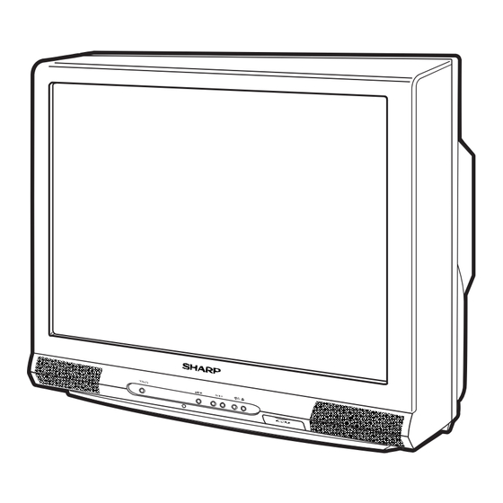
Page 4: Location Of User's Control
32F540 LOCATION OF USER'S CONTROL Front Panel VIDEO/AUDIO IN 2 POWER POWER MENU — VOL Press → On. TERMINALS PULL-OPEN Press again → Off. (INSIDE DOOR) POWER MENU — VOL + CHANNEL UP/DOWN REMOTE CONTROL ( ) Selects next higher channel. -
Page 5: Installation And Service Instructions
32F540 INSTALLATION AND SERVICE INSTRUCTIONS Note: (1) When performing any adjustments to resistor controls and transformers use non-metallic screwdrivers or TV alignment tools. (2) Before performing adjustments, the TV set must be on at least 15 minutes. HIGH VOLTAGE CHECK CIRCUIT PROTECTION The receiver is protected by a 4.0A fuse (F701),... - Page 6 32F540 For adjustments of this model, the bus data is converted to various analog signals by the D/A converter circuit. Note: There are still a few analog adjustments in this series such as focus and master screen voltage. Follow the steps below whenever the service adjustment is required. See "Table-B" to determine, if serv- ice adjustments are required.
- Page 7 TINT-S 0-127 (00h-7Fh) 62 (3Eh) Component Input C-TRAP 0-1 (00h-01h) 0 (00h) AUTO FRESH 0-1 (00h-01h) 0 (00h) SHARP P F 0-1 (00h-01h) 1 (01h) CD MATRIX 0-3 (00h-03h) 2 (02h) B-Y ATT 0-1 (00h-01h) 0 (00h) R-Y ATT 0-1 (00h-01h)
- Page 8 32F540 DATA NOTES FIXED VALUE SERVICE ADJUSTMENT ITEM (HEX) NUMBER RANGE INITIAL VALUE EW CORNER BOTTOM 19-81 (13h-51h) 50 (32h) Offset toward D13. NOISE DET LEVEL 0-3 (00h-03h) 0 (00h) V CENTERING 0-63 (00-3Fh) 36 (24h) V-AGC 0-1 (00h-01h) 0 (00h)
-
Page 9: Service Adjustment
32F540 Holding down both the VOL-up and CH-up buttons on the TV set at service mode for more than 2 seconds will automatically write the above initial values into IC2101. ADJUSTMENT PART REPLACED NOTES NECESSARY UNNECESSARY IC2001 Data is stored in IC2101. - Page 10 1. Enter the service mode and input data of “00h” on "D01". 2. Adjust "D18" data value so that picture is centered. (SCREEN FORMAT 16:9 32F540 ONLY) LEVEL B-AMP Base waveform in step 3. Input data of "00h" on "D20".
-
Page 11: Mts Adjustment
32F540 Ë MTS ADJUSTMENT MTS Level Adjustment 1. Set the sound volume above 1. Monoral signal: 400Hz, 100% modulation 2. Confirm "EX4" data is "5Ah". 3. Vary the "M01" bus data until the voltage to pin (39) of IC3001 to become the value as stated below. -
Page 12: Chassis Layout
32F540 CHASSIS LAYOUT... -
Page 13: Block Diagram
32F540 BLOCK DIAGRAM... -
Page 14: Description Of Schematic Diagrams & Waveforms
32F540 DESCRIPTION OF SCHEMATIC DIAGRAM WAVEFORM MEASUREMENT CONDITIONS: NOTES: 1. Photographs taken on a standard gated color bar 1. The unit of resistance "ohm" is omitted. Ω Ω Ω signal, the tint setting adjusted for proper color. The (K=k =1000... -
Page 15: Schematic Diagrams
32F540 SCHEMATIC DIAGRAMS CRT UNIT... - Page 16 32F540 MAIN-1 UNIT...
- Page 17 32F540...
- Page 18 32F540 MAIN-2 UNIT...
- Page 19 32F540...
- Page 20 32F540 2 LINE Y/C UNIT...
- Page 21 32F540...
-
Page 22: Control Unit
32F540 CONTROL UNIT... - Page 23 32F540...
-
Page 24: Printed Wiring Board Assemblies
32F540 PRINTED WIRING BOARD ASSEMBLIES PWB-A: MAIN Unit (A Side) - Page 25 32F540 PWB-A: MAIN Unit (B Side)
- Page 26 32F540 PWB-B: CRT Unit (Wiring Side) PWB-D: 2 LINE Y/C Unit (Wiring Side) PWB-D: 2 LINE Y/C Unit (Chip Parts Side)
- Page 27 32F540 PWB-F: CONTROL Unit (Wiring Side)
-
Page 28: Replacement Parts List
IC751 VHiPQ09RDA1-1 X PQ090RDA1SZ IC900 VHiCXA2089Q-2Y X CXA2089Q-6T IC1403 VHiPQ05RDA1-1 X PQ050RDA1SZ in USA: Contact your nearest SHARP Parts Distributor to order. For IC2001 RH-iXA418WJZZQ X TMP88CS38BFG location of SHARP Parts Distributor, Please call Toll-Free; 1- IC2040 VHiKiA7045A-1+ X KIA7045AP 800-BE-SHARP... - Page 29 32F540 Ref. No. Part No. Description Code Ref. No. Part No. Description Code D455 VHD1SS133++-1Y X 1SS133++ L802 VP-XF100K0000Y X Peaking, 10µH D501 RH-DX0302CEZZY X DX0302CE L2040 RCiLBA007WJZZ X Oscillation Coil D502 VHD1SS133++-1Y X 1SS133++ D510 RH-DX0441CEZZY X DX0441CE TRANSFORMERS å...
- Page 30 32F540 Ref. No. Part No. Description Code Ref. No. Part No. Description Code C506 VCKYCY1HB103KY X 0.01 Ceramic C783 VCQYTA1HM103J+ X 0.01 Mylar C507 VCKYCY1HB103KY X 0.01 Ceramic C784 VCKYCY1HF103ZY X 0.01 Ceramic C510 RC-FZ0272CEZZ+ X 0.39 100V Mylar C801...
- Page 31 32F540 Ref. No. Part No. Description Code Ref. No. Part No. Description Code C3008 VCKYCY1CF104ZY X 0.1 Ceramic R365 VRS-CY1JF152JY X 1.5k 1/16W Metal Oxide C3009 VCEA0A1CW477M+X 470 Electrolytic å R367 VRN-RL3DB1R2J+ X 1.2 Metal Film C3010 VCE9GA1HW475M+X 4.7 Electrolytic R368 VRD-RA2BE222JY X 2.2k 1/8W...
- Page 32 32F540 Ref. No. Part No. Description Code Ref. No. Part No. Description Code R610 VRD-RM2HD220JY X 22 1/2W Carbon R806 VRS-CY1JF681JY X 680 1/16W Metal Oxide R611 VRW-KQ41C3R3K X 3.3 Cement R807 VRS-CY1JF681JY X 680 1/16W Metal Oxide å R612...
- Page 33 32F540 Ref. No. Part No. Description Code Ref. No. Part No. Description Code R2013 VRS-CY1JF682JY X 6.8k 1/16W Metal Oxide J921 QSOCD0456CEZZ X Socket, S-Video R2021 VRS-CY1JF334JY X 330k 1/16W Metal Oxide J1401 QTANJ1101SEZZ X In Out Jack R2024 VRS-CY1JF472JY X 4.7k 1/16W Metal Oxide...
- Page 34 32F540 Ref. No. Part No. Description Code Ref. No. Part No. Description Code RESISTORS CAPACITORS R850 VRS-SV2HC152J X 1.5k 1/2W Metal Oxide C1401 VCKYCY1HB103KY X 0.01 Ceramic å R851 VRS-SV2HC152J X 1.5k 1/2W Metal Oxide C1402 VCEA0A1AW227M+X 220 Electrolytic å...
- Page 35 32F540 Ref. No. Part No. Description Code Ref. No. Part No. Description Code MISCELLANEOUS PARTS CABINET PARTS VSP1206PB648A X Speaker(L) CCABA0176WEH6 X Front Cabinet Ass'y VSP1206PB648A X Speaker(R) Not Available 1B-1 - Front Cabinet — QCNW-A475WJZZ X Connecting Cord 1B-2...
-
Page 36: Packing Of The Set
32F540 PACKING OF THE SET Polyethylene Bag Operation Manual Infrared R/C Unit Batteries Polyethylene Sheet Buffer Material FRONT Packing Case Use tape to fix the top side of packing case. REAR Use 12 staples to fix the bottom side of packing case. - Page 37 32F540...
- Page 38 32F540 COPYRIGHT © 2004 BY SHARP CORPORATION ALL RIGHTS RESERVED. No part of this publication may be reproduced, stored in a retrieval system, or transmitted in any form or by any means, electronic, mechanical, photocopying, recording, or otherwise, without prior written permission of the publisher.
Need help?
Do you have a question about the 32f540 and is the answer not in the manual?
Questions and answers