Table of Contents
Advertisement
Quick Links
Advertisement
Table of Contents

Subscribe to Our Youtube Channel
Related Manuals for AudioArts Engineering D-76


Summary of Contents for AudioArts Engineering D-76
- Page 1 D-76 Digital Audio Console echnical anual February 2015...
- Page 2 D-76 Digital Audio Console Technical Manual ©2015 Audioarts Engineering* ® AUDIOARTS ENGINEERING 600 Industrial Drive New Bern, North Carolina 28562 252-638-7000 *a division of Wheatstone Corporation D-76 / Feb 2015...
- Page 3 This equipment must be installed and wired properly in order to assure compliance with FCC regulations. Caution! Any modifications not expressly approved in writing by Wheatstone could void the user's authority to operate this equipment. D-76 / Mar 2015 D-76 / June 2015...
- Page 4 Again, to avoid ANY possibility of this damage, whenever possible we strongly recommend powering down the console before replacing any modules. D-76 / Feb 2015...
-
Page 5: Gain Structure
Analog Bus Output Gain (D-A Converter) • • The analog output DAC circuits are designed so that a -20dBFS digital input signal will yield a +4dBu analog output with the channel fader at nominal. D-76 / Feb 2015... - Page 6 Since the D-76 console meters are true digital reading meters, they will always show the console's digital levels, and whether there are any "overs"...
-
Page 7: Table Of Contents
Digital Audio Connections ..................1-7 Unbalanced Connections (analog audio) ..............1-8 Modules Layout ................1-8 Input Daughter Cards Installation ..........1-9 D-76-12 Console Modules Layout Drawing ........ 1-10 D-76-20 Console Modules Layout Drawing ........ 1-11 Chapter 2 - Quad Mic Preamp Overview ..................2-2 Internal Programming Options ............. - Page 8 Internal Programming Options ............. 5-3 Cue Interrupt ......................5-3 CR/Cue Mute ......................5-3 On-Air Tally Follows Program ..................5-3 Hook-Ups ..................5-4 RJ-45 Connector Pinout Drawing ..........5-5 Control Room Module Signal Flow Diagram ....... 5-6 page Contents – 2 D-76 / Feb 2015...
- Page 9 Line Select Module Signal Flow Diagram ........8-5 Chapter 9 - Network Module (IP-76) - optional Module Overview ................9-2 Adding IP-76 to the Peripheral Devices Tab ....... 9-2 page Contents – 3 D-76 / Feb 2015 D-76 / May 2016...
- Page 10 Digital Timer .................. 10-2 Console Clock ................10-3 Setting The Time .......................10-3 Capacitor Backup .....................10-3 Operational Modes ....................10-3 24 Hour Mode .......................10-3 External Sync ......................10-3 Dim ........................10-4 Appendix Replacement Parts List ..............A-2 page Contents – 4 D-76 / Feb 2015...
- Page 11 Digital Audio Connections ..................1-7 Unbalanced Connections (analog audio) ..............1-8 Modules Layout ................1-8 Input Daughter Cards Installation ..........1-9 D-76-12 Console Modules Layout Drawing ........ 1-10 D-76-20 Console Modules Layout Drawing ........ 1-11 page 1 – 1 D-76 / Feb 2015...
-
Page 12: Console Overview
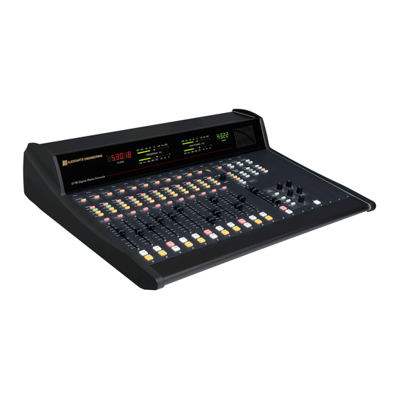
Installation and Power Console Overview The D-76 is a tabletop, modular console available in a 12-channel or 18-channel frame. Sporting a sleek new profile, the new D-76 comes standard with sample rate conversion, ample mic preamps, plenty of stereo busses, and a comprehensive monitor section that provides separate feeds to control room/headphone and studio monitor outputs —... -
Page 13: Unpacking The Console
19-7/16" 4 HOLES, D= 3/ 16" USE #8 SCREWS TO ATTACH TO COUNTER 1-1/2" 37-3 /4" D-76-20 (25-3/ 4" D- 76-12) 40-3 /4" D-76-20 (28-3/ 4" D-76-12) 42 -3/8" D-76-20 (30- 1/4" D -76-12) page 1 – 3 D-76 / Feb 2015... -
Page 14: System Ground
Note that as supplied from the factory, console rackmount power supply common, audio ground, and the D-76 mainframe are connected together at the console, but are NOT connected to electrical ground and the chassis of the power supply. Safety requirements dictate that a positive connection from the console mainframe to electrical ground be made in the completed installation. -
Page 15: Further Grounding Details
10-32 screws and insulating washers between rails and faceplates. Once the system is properly grounded, proceed with the console power supply installation and connection (next section). page 1 – 5 D-76 / Feb 2015... -
Page 16: Power Supply
Rear view of the SPS-100 rackmount power supply The D-76 console is powered by an Audioarts Model SPS-100 rackmount power supply. This unit occupies two 19" wide rack spaces (total height 3-1/2"). Convection cooled, it requires ample ventilation space above and below it. The SPS-100 generates heat in the course of normal operation —... -
Page 17: Energizing
You may now proceed to wire up audio and control connections. Audio and Control Wiring Audio I/O and control connections to the D-76 console are made via RJ-45 connectors, and 12-pin plug terminal. Digital Audio Connections CABLE –... -
Page 18: Unbalanced Connections (Analog Audio)
Modules must be placed in the slots indicated on the module layout drawings that follow. page 1 – 8 D-76 / Feb 2015 D-76 / Jan 2016... -
Page 19: Input Daughter Cards Installation
Flip the switch to the ON position for a SPDIF input or to the OFF position for an AES input. In addition to using the switch, the input must be wired correctly – see Digital Audio Connections on page 1-7 and 1-8. page 1 – 9 D-76 / Feb 2015... - Page 20 2. masTEr OuTpuT, CONTrOl rOOm, sTudiO CONTrOl aNd OpTiONal supErphONE aNd NETwOrk mOdulEs havE ThEir dEdiCaTEd slOTs (as shOwN). 3. lasT ThrEE slOTs aT ThE righT ENd Of ThE framE shOuld bE usEd fOr OpTiONal liNE sElECT mOdulE. D-76-12 CONSOLE MODULES LAYOUT page 1 – 10...
- Page 21 2. masTEr OuTpuT, CONTrOl rOOm, sTudiO CONTrOl aNd OpTiONal supErphONE aNd NETwOrk mOdulEs havE ThEir dEdiCaTEd slOTs (as shOwN). 3. lasT ThrEE slOTs aT ThE righT ENd Of ThE framE shOuld bE usEd fOr OpTiONal liNE sElECT mOdulE. D-76-20 CONSOLE MODULES LAYOUT page 1 – 11...
- Page 22 Phantom Power ......................2-3 Hook-Ups ..................2-3 Audio Input Connections ....................2-3 Audio Output Connections ..................2-3 Power Connections ....................2-4 Plug Terminal / RJ-45 Pinout Drawing .......... 2-5 Installing The Optional Second QMP4-76 Mic Preamp ....2-6 page 2 – 1 D-76 / Feb 2015...
-
Page 23: Overview
‑22dBu to +16dBu (note maximum preamp gain is +76dB). Mounted on the QMP4‑76 PCB the 12‑position plug terminal is for audio input connections, while the four‑port ganged RJ‑45 is for output connections. page 2 – 2 D-76 / Feb 2015... -
Page 24: Internal Programming Options
RJ‑45 #2 Pin 1 – HI RJ‑45 #2 Pin 2 – LO Mic 2 Out RJ‑45 #2 Pin 3 – HI RJ‑45 #2 Pin 4 – SH RJ‑45 #2 Pin 6 – LO page 2 – 3 D-76 / Feb 2015... - Page 25 Pin 4 – +Phantom V Pin 5 – +V In Pin 6 – +V In Pin 7 – ‑V In Pin 8 – ‑V In Pin 9 – Analog Ground Pin 10 – Analog Ground page 2 – 4 D-76 / Feb 2015...
- Page 26 MIC 2 OUT LO MIC 4 OUT LO MIC 2 OUT HI MIC 4 OUT HI MIC 2 OUT SH MIC 4 OUT SH RJ-45 RJ-45 MIC 2 OUT LO MIC 4 OUT LO page 2 – 5 D-76 / Feb 2015...
-
Page 27: Installing The Optional Second Qmp4-76 Mic Preamp
Connect the required audio wiring to the 12‑pin plug terminal and the four‑port ganged RJ‑45 on the QMP4‑76 card, referring to the “Hook‑Ups” chart (see pages 2‑3 ‑ 2‑5); • Close the meterbridge. This completes the optional QMP4‑76 installation procedure. page 2 – 6 D-76 / Feb 2015... - Page 28 External Start/Stop ....................3-8 Ready ........................3-8 Talkback to Control Room ..................3-8 On Tally ........................3-8 B Tally ........................3-9 RJ-45 Connector Pinout Drawing ..........3-10 IN-76 Stereo Line Input Module Signal Flow Diagram ....3-11 page 3 – 1 D-76 / Feb 2015...
-
Page 29: Chapter 3 - Stereo Line Input (In-76)
The OFF switch’s LED can be controlled by an external source machine to act as a “ready” indicator. page 3 – 2 D-76 / Feb 2015... -
Page 30: Internal Programming Options
B is used. Talkback Typically, one of the D-76 console’s input modules will be used for the control room (CR) console operator’s microphone. The third position of the dipswitch SW1 allows that microphone to also function as a talkback mic. It places the signal (pre-fader, pre-on/off) onto the console’s talkback bus. -
Page 31: Attenuation
OFF button. This feature is enabled by moving the dipswitch position 1 to the right (on). SW1 position 1 enables the EFS feature UTIL Pre-Fade / Pre-On Defeat As shipped from the factory, D-76 input modules feed the UTIL bus pre-fade, pre-on. This feature can be defeated for all input modules via position 4 of... -
Page 32: B Source Logic Options
4. Connect the external sync cable to CT‑28 and find a convenient opening at the rear of the console to pass the cable to the outside world page 3 – 5 D-76 / Feb 2015... - Page 33 The internal sample rate should be set to the same frequency as the external sync to avoid drastic sample rate changes if the external sync is lost. page 3 – 6 D-76 / Feb 2015...
-
Page 34: Hook-Ups
“Remote location” can also refer to a remote source machine that is feeding its audio to the module in question. A contact closure (which may be sourced by the external machine), will activate the module’s channel ON and OFF switches. page 3 – 7 D-76 / Feb 2015... -
Page 35: Cough
Lets the module’s channel ON switch control an on-air light or other “microphone on” indicator at a remote location. This control function provides a continuous closure to Digital Ground at Logic RJ-45 #2 Pin 3 (On Tally) whenever the module is ON. page 3 – 8 D-76 / Feb 2015... -
Page 36: B Tally
Note that this output always functions regardless of the REM B setting on the MBR-76. However, you will most likely want to enable B remote logic if you are using the B Tally. page 3 – 9 D-76 / Feb 2015... - Page 37 LINE B RT IN LO Logic Connection DIGITAL GROUND DIGITAL GROUND COUGH REMOTE ON READY ON TALLY RJ-45 START RJ-45 REMOTE OFF STOP TB TO CR START/STOP COM B TALLY +5V DIGITAL +5V DIGITAL page 3 – 10 D-76 / Feb 2015...
-
Page 38: In-76 Stereo Line Input Module Signal Flow Diagram
QMP4-76 ADC-76 Analog MIC PREAMP DAUGHTER CARD SAMPLE Digital RATE INPUT RECEIVER Digital CONVERTER (SRC) STEREO LINE INPUT SRC-76 ANALOG OR DIGITAL DAUGHTER CARD IN-76 Stereo Line Input Module Signal Flow Diagram page 3 - 11 D-76 / Feb 2015... - Page 39 Module Overview ................4-2 Internal Programming Options ............. 4-3 Sampling Frequency for Console Outputs ......... 4-3 Hook-Ups ..................4-4 RJ-45 Connector Pinout Drawing ..........4-5 Output Module Signal Flow Diagram ........... 4-6 page 4 – 1 D-76 / Feb 2015...
-
Page 40: Chapter 4 - Output Module (Om-76)
Auxiliary, and Utility outputs. All analog outputs are calibrated with multi-turn trimpots located on the OM-76 PCB below the RJ-45 connectors. The D-76 console has two pairs of left-right VU meters, PGM and SWT (switched), located on the console’s meterbridge. The switched meter fol-... -
Page 41: Internal Programming Options
SW3 and SW4 on the MBR-76 board to correctly embed the sample rate information in the output AES data stream. Table 2 shows the dipswitch settings. TABLE 2 FREQUENCY 48 kHz *factory default settings *44.1 kHz 32 kHz page 4 – 3 D-76 / Feb 2015... -
Page 42: Hook-Ups
RJ-45 #9 Pin 2 – LO RJ-45 #10 Pin 1 – HI UTIL Lt Out RJ-45 #10 Pin 2 – LO RJ-45 #10 Pin 3 – HI UTIL Rt Out RJ-45 #10 Pin 6 – LO page 4 – 4 D-76 / Feb 2015... - Page 43 AUX RT OUT LO UTIL AES OUT HI UTIL LT OUT HI UTIL LT OUT LO UTIL AES OUT LO UTIL RT OUT HI RJ-45 RJ-45 UTIL RT OUT LO page 4 – 5 D-76 / Feb 2015 D-76 / Nov 2015...
-
Page 44: Om-76 Output Module Signal Flow Diagram
UTIL RT UTIL EXT2 UTIL MONITOR CUE LT MONITOR UTIL CUE LOGIC CUE RT FROM CONSOLE MONITOR CONTROL BUSSES OM-76 FRONT PANEL TEL MONITOR TEL MONITOR SWITCHES OM-76 Output Module Signal Flow Diagram page 4 - 6 D-76 / Feb 2015... - Page 45 Internal Programming Options ............. 5-3 Cue Interrupt ......................5-3 CR/Cue Mute ......................5-3 On-Air Tally Follows Program ..................5-3 Hook-Ups ..................5-4 RJ-45 Connector Pinout Drawing ..........5-5 Control Room Module Signal Flow Diagram ....... 5-6 page 5 – 1 D-76 / Feb 2015...
-
Page 46: Chapter 5 - Control Room Module (Cr-76)
h eadphoneamplifier. All user wiring to and from the CR‑76 module takes place at the six RJ‑45 connectors mounted at the top of the module and located underneath the hinged meterbridge. page 5 – 2 D-76 / Feb 2015... -
Page 47: Internal Programming Options
A dipswitch setting defeats this PGM assign dependence (the module must still have CR mute enabled and be turned on to activate the air tally). SW1 position 6 defeats the air tally dependence on PGM assign page 5 – 3 D-76 / Feb 2015... -
Page 48: Hook-Ups
RJ‑45#5 Pin 2 – LO RJ‑45#5 Pin 3 – HI CUE Rt Out RJ‑45#5 Pin 6 – LO RJ‑45#6 Pin 1 – On‑Air Tally Relay N.O. RJ‑45#6 Pin 2 – On‑Air Tally Relay COM page 5 – 4 D-76 / Feb 2015... - Page 49 CR RT OUT LO HDPN RT OUT LO On-AIR TALLY RELAY N.O. CUE LT OUT HI CUE LT OUT LO ON-AIR TALLY RELAY COM CUE RT OUT HI RJ-45 RJ-45 CUE RT OUT LO page 5 – 5 D-76 / Feb 2015...
-
Page 50: Cr-76 Control Room Module Signal Flow Diagram
SW1 POS 2 INTERRUPT CR OUT MONO FET SW CUE TO UTIL LT CR SW1 POS 5 CONTROL CUE TO RT CR ROOM SW1 POS 4 CR-76 Control Room Module Signal Flow Diagram page 5 - 6 D-76 / Feb 2015... - Page 51 Internal Programming Options ............. 6-3 External Talkback Mute/Dim ..................6-3 Studio Dim ........................6-3 Studio Pre Mute ......................6-3 Hook-Ups ..................6-4 RJ-45 Connector Pinout Drawing ..........6-5 Studio Control Module Signal Flow Diagram ......6-6 page 6 – 1 D-76 / Feb 2015...
-
Page 52: Chapter 6 - Studio Control Module (Sc-76)
The TALKBACK master level control sets the level of this talkback interrupt signal. All user wiring to and from the SC-76 module takes place at the six RJ-45 connectors mounted at the top of the module and located underneath the hinged meterbridge. page 6 – 2 D-76 / Feb 2015... -
Page 53: Internal Programming Options
When this is done it overrides the studio dim function (that is, the main studio out will always mute, never dim when studio pre mute is activated). SW1 position 4 causes studio pre to mute page 6 – 3 D-76 / Feb 2015... -
Page 54: Hook-Ups
RJ-45#4 Pin 6 – LO RJ-45#5 Pin 1 – HI TB Out RJ-45#5 Pin 2 – LO RJ-45#6 Pin 1 – Tally 2 Relay N.O. RJ-45#6 Pin 2 – Tally 2 Relay COM page 6 – 4 D-76 / Feb 2015... - Page 55 ST PRE RT OUT HI RJ-45 RJ-45 ST RT OUT LO ST PRE RT OUT LO TB OUT HI TALLY 2 RELAY N.O. TB OUT LO TALLY 2 RELAY COM RJ-45 RJ-45 page 6 – 5 D-76 / Feb 2015...
-
Page 56: Sc-76 Studio Control Module Signal Flow Diagram
LOW VOLTAGE TALLY 2 RELAY CONTACTS FROM CONSOLE CONTROL LOGIC EXT 1 MUTE INTRPT ST OUT EXT 2 ST PRE OUT EXT1 EXT2 UTIL UTIL STUDIO SC-76 Studio Control Module Signal Flow Diagram page 6 - 6 D-76 / Feb 2015... -
Page 57: Rj-45 Connector Pinout Drawing
Timer Restart ......................7-4 Tallies ..........................7-4 Cue Dropout .......................7-4 External Input ......................7-4 Gain Trimpots ......................7-4 Hook-Ups ..................7-5 External Start/Stop .....................3-6 RJ-45 Connector Pinout Drawing ..........7-6 Superphone Module Signal Flow Diagram ........7-7 page 7 – 1 D-76 / Feb 2015... -
Page 58: Module Overview
DJ microphone QMP4-76 channel both to the IN-76 input and the SP-76 external input. If the SP-76 dipswitch is set to enable the external input the DJ’s voice is always sent to the callers. page 7 – 2 D-76 / Feb 2015... -
Page 59: Automatic Features
SW1 position 6 mutes the control room and activates the air tally when the phone module is ON* *factory default settings SW1 position 5 mutes studio when the phone module is ON page 7 – 3 D-76 / Feb 2015... -
Page 60: Timer Restart
CR9 – sets the module’s output level to Hybrid 1 CR10 – sets the module’s output level to Hybrid 2 The first two trimpots are accessible through holes in the module faceplate. page 7 – 4 D-76 / Feb 2015... -
Page 61: Hook-Ups
START/STOP COMMON and START; when the module’s OFF switch is pressed, an opto‑isolated closure takes place between START/STOP COMMON and STOP. These may be used to control a remote tape machine for recording phone segments. page 7 – 5 D-76 / Feb 2015 D-76 / June 2015... - Page 62 HYBRID 1 OUT HI HYBRID 2 OUT HI HYBRID 1 OUT LO HYBRID 2 OUT LO RJ-45 RJ-45 CALLERS OUT HI START START/STOP COM CALLERS OUT LO STOP RJ-45 RJ-45 START/STOP COM page 7 – 6 D-76 / Feb 2015...
-
Page 63: Sp-76 Superphone Module Signal Flow Diagram
EXT IN ENABLE MICS FET SW TRIM TEL MONITOR SUM OF CALLERS TRIM TO HYBRID 1 TB TO CALLER TB MONITOR TRIM TO HYBRID 2 SUPERPHONE INPUT SP-76 Superphone Module Signal Flow Diagram page 7 - 7 D-76 / Feb 2015... -
Page 64: Rj-45 Connector Pinout Drawing
Line Select Module (LS-76; optional) Chapter Contents Module Overview ................8-2 Internal Programming Options ............. 8-2 Hook-Ups ..................8-3 RJ-45 Connector Pinout Drawing ..........8-4 Line Select Module Signal Flow Diagram ........8-5 page 8 – 1 D-76 / Feb 2015... -
Page 65: Module Overview
(note that an eighth RJ‑45 is not used). Internal Programming Options There are no internal programming options on the LS‑76 module. page 8 – 2 D-76 / Feb 2015... -
Page 66: Hook-Ups
RJ‑45 #6 Pin 6 – LO RJ‑45 #7 Pin 1 – HI Line Lt Out RJ‑45 #7 Pin 2 – LO RJ‑45 #7 Pin 3 – HI Line Rt Out RJ‑45 #7 Pin 6 – LO page 8 – 3 D-76 / Feb 2015... - Page 67 RJ-45 RJ-45 LINE 5 RT IN LO LINE 6 RT IN LO LINE LT OUT HI LINE LT OUT LO LINE RT OUT HI RJ-45 RJ-45 NOT USED LINE RT OUT LO page 8 – 4 D-76 / Feb 2015...
- Page 68 LINE 1 LINE 2 LINE 3 LINE 4 LINE 5 LINE 6 LINE SELECT MODULE LS-76 Line Select Module (analog) Signal Flow Diagram page 8 - 5 D-76 / Feb 2015...
-
Page 69: Connector Pinout Drawing
IP-76 Menus ................... 9-13 Internal Programming Functions ..........9-13 Hook-Ups ..................9-13 Audio Connection ......................9-13 Logic Connection .......................9-14 Ethernet Interface ......................9-14 Typical Ethernet Cable ..................9-14 RJ-45 Connector Pinout Drawing ................9-15 page 9 – 1 D-76 / Feb 2015 D-76 / May 2016... -
Page 70: Module Overview
Adding IP-76 to the Peripheral Devices Tab In order to utilize all the features of the D-76 console in a WheatNet-IP system the device must be added to the System Peripheral Devices tab (in previous versions this was the System 3rd Party Devices tab) in the Wheatstone WheatNet‑IP Navigator program (aka the Navigator GUI). - Page 71 9 – 3 D-76 / Feb 2015 D-76 / May 2016...
- Page 72 N E T W O R K M O D U L E The System Crosspoint screen will now include the D‑76 console’s sources and destinations. page 9 – 4 D-76 / Feb 2015 D-76 / May 2016...
-
Page 73: Wheatnet-Ip Ip76 Gui
Remove to delete the device currently highlighted in the list. To the right of these buttons is the Online check box, which is used to toggle the GUI connection to the highlighted device between online (checked) and offline (not checked). page 9 – 5 D-76 / Feb 2015... -
Page 74: Ip76 Gui Menu
The WheatNet‑IP System menu is used to manage signal sets within the IP‑76 GUI: • File Open... – Used to open a saved signal set • File Save... – Used to save the current signal set page 9 – 6 D-76 / Feb 2015... - Page 75 Yes you will be prompted for the location and name of the saved file, and also given a chance to write a brief description of this saved data set, but for now just click No. page 9 – 7 D-76 / Feb 2015...
-
Page 76: Hardware
• Add New Device... – Used to set up a new IP‑76 for the GUI to communicate with – brings up a dialog box to set a name, device type, and IP address: page 9 – 8 D-76 / Feb 2015... -
Page 77: Help
– a confirm dialog allows you to change your mind. Help The Help menu gives additional information about the IP‑76 GUI: • About... – Used to show the version of the IP‑76 GUI. page 9 – 9 D-76 / Feb 2015... -
Page 78: Device Properties
A look at the various signals for the D‑76 shown in the System Crosspoint view page 9 – 10 D-76 / Feb 2015 D-76 / May 2015... -
Page 79: Display Brightness
Factory default settings for brightness are: Normal Level (1‑16): 10 AutoDim Level (1‑16): 4 AutoDim Timeout (minutes): 10 page 9 – 11 D-76 / Feb 2015 D-76 / May 2015... -
Page 80: I/O Connections
• Destination Name – The location of the current source is shown at the center of display. • BLADE Name – The 3rd line displays the name of the BLADE that the D-76 is associated with. • The bottom line of the display, “3PD” and “ACI”, in green indicates a good network connection;... -
Page 81: Ip-76 Menus
RJ‑45 #4 Pin 1 – HI RJ‑45 #4 Pin 2 – LO RJ‑45 #5 Pin 1 – HI RJ‑45 #5 Pin 2 – LO RJ‑45 #6 Pin 1 – HI RJ‑45 #6 Pin 2 – LO page 9 – 13 D-76 / Feb 2015... -
Page 82: Logic Connection
Typical Straight-Through Cable TXD + White/Orange 1 White/Orange TXD - Orange 2 Orange RXD + White/Green White/Green Blue Blue RJ-45 RJ-45 Plug White/Blue White/Blue Plug RXD - Green Green White/Brown White/Brown Brown Brown page 9 – 14 D-76 / Feb 2015... - Page 83 DIGITAL GROUND TXD + LOGIC 1 IN/OUT TXD - LOGIC 2 IN/OUT RXD + LOGIC 3 IN/OUT RJ-45 RJ-45 LOGIC 4 IN/OUT LOGIC 5 IN/OUT RXD - LOGIC 6 IN/OUT +5V DIGITAL page 9 – 15 D-76 / Feb 2015...
- Page 84 Chapter Contents Overview ..................10-2 Digital Timer .................. 10-2 Console Clock ................10-3 Setting The Time .......................10-3 Capacitor Backup .....................10-3 Operational Modes ....................10-3 24 Hour Mode .......................10-3 External Sync ......................10-3 Dim ........................10-4 page 10 – 1 D-76 / Feb 2015...
-
Page 85: Overview
HOLD button allows you to hold the display for a longer viewing duration, while still allowing the counter to continue in the background. Releasing the button will then display the current count. page 10 – 2 D-76 / Feb 2015... -
Page 86: Console Clock
2 of CT8) or an external 60Hz signal (input on pin 1 of CT9, referenced to digital common at pin 2 of CT9). SW1 position 2 enables synchronization to the 1Hz input SW1 position 3 enables synchronization to the 60Hz input page 10 – 3 D-76 / Feb 2015... -
Page 87: Dim
1 of CT10 and referenced to digital common at pin 2 of CT10. The timer and clock displays can be dimmed for operation in areas with low ambient lighting. SW1 position 4 enables clock and timer display dimming. page 10 – 4 D-76 / Feb 2015... -
Page 88: Replacement Parts List
Contents Replacement Parts List ..............A-2 For the most part there are no user-replaceable parts in the D-76 console. Exceptions are those controls and components that in the course of normal use may need maintenance (i.e., faders, pots, ON/OFF switches, etc.). - Page 89 A P P E N D I X REPLACEMENT PARTS D-76 DIGITAL AUDIO CONSOLE COMPONENT DESCRIPTION WS P/N IN-76 MODULE INPUT MODULE 011200 SP-76 MODULE SUPERPHONE MODULE 011201 OM-76 MODULE OUTPUT CONTROL MODULE 011202 CR-76 MODULE CONTROL ROOM MODULE 011203...
- Page 90 A P P E N D I X REPLACEMENT PARTS D-76 DIGITAL AUDIO CONSOLE COMPONENT DESCRIPTION WS P/N 220145 I/O CONNECTOR 4 PORT GANGED R/A SHIELDED RJ-45 CONNECTORS 260069 I/O CONNECTOR 1x2 PORT STACKED R/A SHIELDED RJ-45 CONNECTORS 260089 I/O CONNECTOR...
Need help?
Do you have a question about the D-76 and is the answer not in the manual?
Questions and answers