Table of Contents
Advertisement
Quick Links
Advertisement
Table of Contents

Related Manuals for Diamond ICE32A


Summary of Contents for Diamond ICE32A
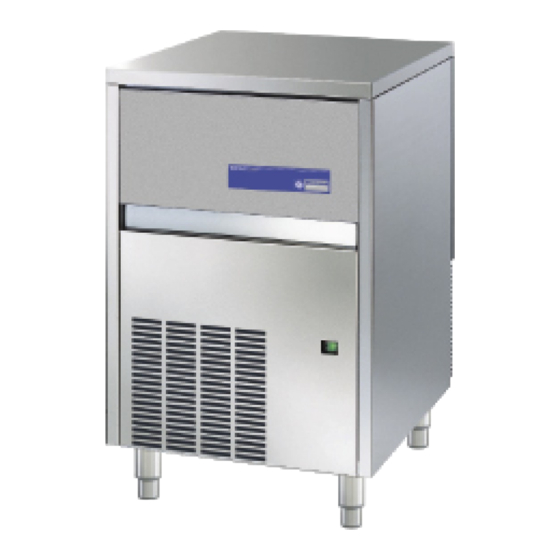
- Page 1 11/2007 Mod: ICE32A Production code: CB316A...
- Page 2 AUTOMATIC ICE-CUBE MAKER INSTRUCTIONS AND WARNINGS It is strictly forbidden to reproduce this instruction manual or any part thereof.
-
Page 7: Table Of Contents
Dear Customer, Congratulations on having chosen a quality product which will certainly fully meet your expectations. Thank you for having purchased one of our products. Please read this instruction manual carefully before using your new automatic ice-cube maker. TABLE OF CONTENTS 1 IMPORTANT ADVICE AND RECOMMENDATIONS 2 TECHNICAL SPECIFICATIONS 3 ADVICE ABOUT TRANSPORTATION... -
Page 8: Important Advice And Recommendations
1 IMPORTANT ADVICE AND RECOMMENDATIONS This instruction manual forms an integral part of the automatic ice-cube maker (also more simply called “appliance” in the text) and must be kept for possible future consultation. In the event of the appliance being sold or transferred to another person, this manual must be handed over to the new user, in order to enable him to become familiar with the operation of the equipment and the corresponding advice and recommendations. -
Page 9: Advice About Transportation
This appliance does not contain coolant that damages the ozone layer. ‼ The Manufacturer shall not be liable for any damage to the environment, animals, persons or objects caused by incorrect installation. 2 TECHNICAL DATA (Fig. 1) The voltage and frequency are given on the data plate on the appliance. Refer to this data plate to check compliance. -
Page 10: Positioning
5.2 POSITIONING ‼ The appliance must be installed in a hygienically clean location; it is advisable to avoid rooms like cellars and store-rooms, because failure to meet hygiene requirements is likely to lead to the formation and proliferation of bacteria in the appliance. The appliance can operate at an ambient temperature of between 10°C and 43°C. -
Page 11: Connection To The Electricity Mains
5.3.b DRAIN (Fig. 7) Fix the water drain pipe (10) in the housing provided on the rear of the appliance (front for the flush-mounting models). Make sure that: • the pipe is a hose • the internal diameter is 22 mm, as required •... -
Page 12: Starting-Up Models With Continuous Delivery
Once the appliance has been correctly connected to the electricity mains, water mains and water drain system, it can be started up as follows: a) turn on the water supply tap (8 in Fig. 4) b) insert the plug (if any) in the socket and switch on the power supply by means of the relative switch fitted during the installation phase (7 in Fig. -
Page 13: Adjusting Dispensed Quantity
8.1.a ADJUSTING DISPENSED QUANTITY (Fig. 11) ‼ IMPORTANT: • the operations described below must be performed by a specialized technician, and only after disconnecting the appliance from the electricity mains • all operations that require handling of parts made of metal plate must be carried out wearing suitable gloves to prevent cuts The appliance is provided with an electronic device for adjusting the quantity of ice dispensed each time. -
Page 14: Cleaning And Sanitizing Operations
9.3 CLEANING AND SANITIZING OPERATIONS A cleaning and sanitizing kit specifically designed for this appliance is available from your dealer. ‼ Do not use corrosive substances to remove limescale from the appliance, because this will invalidate the warranty, and may cause serious damage to the materials and components of the appliance. - Page 29 Check out Procedure for Service for CB Anomaly THE ICE MAKER DOESN’T WORK Cause Remedy There is no supply mains voltage Check the user’s electrical system Bin thermostat out of order Replace the bin thermostat Safety thermostat of the water condenser out of Replace the safety thermostat order Contactor out of order...
- Page 30 THE ICE MAKER REMAINS WITHOUT WATER IN THE MIDDLE OR AT Anomaly THE END OF THE CYCLE Cause Remedy Dirty spray nozzles Clean or replace the spray nozzles Water leakage from the basin Check possible breakings Filter of the water inlet valve clogged Clean the filter Anomaly THE ICE MAKER DOESN’T SPRAY WATER...
- Page 31 Anomaly THE ICE MAKER REMAINS IN THE DEFROSTING PHASE Cause Remedy Faulty evaporator thermostat Replace the evaporator thermostat • Check the electric feeding • The hot gas valve doesn’t open Replace the valve coil • Replace the valve Timer locked Replace the timer Anomaly NOT REGULAR OR INCOMPLETE DEFROSTING...
- Page 32 Anomaly WATER LEAKAGES Cause Remedy Inlet or outlet pipe not connected Check connections The pump is leaking Replace the pump Slack pipe clips Check the clamp of the clips The bin water-outlet joint is slack or badly Check or fasten connected Anomaly IRREGULAR OR OPAQUE ICE CUBE...
- Page 33 Anomaly NOISY COMPRESSOR Cause Remedy Extreme mechanical wear Replace the compressor Anomaly NOISY PUMP Cause Remedy Worn bearings Replace the pump Plate fixing Fasten the screws Anomaly THE PUMP LEAKS WATER Cause Remedy Slack pipe-clips Check and clamp the clips Worn ceramic seal Replace the pump External gasket broken...
- Page 34 Anomaly INTERVENTION OF THE USER’S MAIN SWITCH Cause Remedy Compressor: short circuit and/or low dielectric Replace the component strength Pump: short circuit and/or low dielectric strength Replace the component Hot gas valve: short circuit and/or low dielectric Replace the component strength Thermostat: low dielectric strength Replace the component...
- Page 35 ICE CUBE MAKERS “SPRAYERS” SYSTEM Last Update: 04/04/2011 The following diagram shows the main concepts of the ice cube Each ice maker uses the properties of compression and makers working (‘sprayers’ system). expansion of the liquefiable gases; its main principle is that each change of bodies state is got by producing or absorbing heat.
- Page 36 The working of this machine is cyclical. Each cycle is divided into Production Phase of the Ice Cubes two phases: ice cubes are produced during the first phase and fall The hot gas valve is closed; the refrigerating fluid, after in the built-in bin during the second phase.
- Page 37 Compressor Refrigerating Filter + Capillar Tube The refrigerant filter stops possible impurities and the circuit It sucks up the gases, generated by the evaporator by means of humidity. suction line compresses them, increasing their The gas, in liquid status, goes to the evaporator through this temperature and pressure.
- Page 38 Ice cubes production Defrosting The hot gas valve is closed; the compressed gas from the The hot gas valve is open; the compressed gas from the compressor, is piped to the condenser in order to get cool. compressor, is piped to the evaporator, bypassing the condenser.
- Page 39 The following diagram shows the main concepts of the hydraulic Water-inlet valve circuit: It works during the defrosting phase and allows the water to flow on the evaporator, having two goals: 1 . one is to warm the evaporator help, in this way, the ice cubes detaching; 2 .
- Page 40 The following diagram shows the main concepts of the electric The following scheme shows this working system: circuit: Timer Pump Only in the ice Water-inlet Water-inlet production phase valve valve (Evaporator) (Condenser) Safety Utilizer thermostat Unit no on CB1565W Hot gas Bin thermostat valve NB: some components of the electrical circuit (called Utilizer...
- Page 41 Ice cubes production Defrosting The timer, in the first phase, starts up the pump and the utilizer The timer, once reached the set up time, simultaneously units, as described in the scheme of the previous page. commutes three contacts, letting the defrosting phase begin. Evaporator thermostat Hot gas...
- Page 42 Controls systems Safety systems Hot gas valve – The opening of the valve permits to pipe the Safety thermostat – Placed on the condenser of the water refrigerating fluid (overheated after the compression) directly to models. the evaporator, without letting it pass through the condenser It stops the machine working, when the temperature of the water thus warming up the evaporator.
- Page 43 ÷ ÷ ÷ LINE EVAPORATOR GREEN LIGHT SWITCH (on-off) THERMOSTAT THERMOSTAT Hydraulic Circuit Refrigerating Circuit Electric Circuit TIMER CAMME 4 CAMME 2 CAMME 1 MOTOR CAMME 3 CONDENSER WATER SUPPLY CAPILLAR TUBE WATER INLET VALVE PUMP VALVE EVAPORATOR COMPRESSOR SUCTION + SPRAY BAR LINE GREEN LIGHT SWITCH...
- Page 44 ÷ ÷ ÷ LINE EVAPORATOR GREEN LIGHT SWITCH THERMOSTAT (ON-OFF) SAFETY THERMOSTAT THERMOSTAT Hydraulic Circuit Refrigerating Circuit Electric Circuit TIMER CAMME 2 CAMME 1 CAMME 4 CAMME 3 MOTOR CONDENSER CONDENSER PRESSURE-SWITCH WATER WATER CAPILLAR DRAIN SUPPLY TUBE WATER INLET VALVE WATER SUPPLY...
- Page 45 ÷ ÷ ÷ LINE EVAPORATOR GREEN LIGHT SWITCH THERMOSTAT ON-OFF THERMOSTAT Hydraulic Circuit Refrigerating Circuit Elctric Circuit TIMER CAMME 3 CAMME 4 CAMME 2 CAMME 1 MOTOR CONDENSER CONDENSER PRESSURE-SWITCH WATER CAPILLAR SUPPLY TUBE WATER INLET VALVE PUMP HOT GAS VALVE EVAPORATOR COMPRESSOR...
- Page 46 ÷ ÷ ÷ LINE EVAPORATOR GREEN LIGHT SWITCH THERMOSTAT ON-OFF SAFETY THERMOSTAT THERMOSTAT Hydraulic Circuit Refrigerating Circuit Electric Circuit TIMER CAMME 4 CAMME 3 CAMME 2 CAMME 1 MOTOR CONDENSER CONDENSER PRESSURE-SWITCH WATER WATER CAPILLAR DRAIN SUPPLY TUBE WATER INLET VALVE WATER SUPPLY...
- Page 47 HP SAFETY PRESSURE SWITCH LINE EVAPORATOR GREEN LIGHT SWITCH ON-OFF THERMOSTAT THERMOSTAT Hydraulic Circuit Refrigerant Circuit CONTACTOR Electric Circuit TIMER CAMME 3 CAMME 1 CAMME 4 CAMME 2 MOTOR CONDENSER CONDENSER PRESSURE SWITCH CONTACTOR WATER CAPILLARY COIL SUPPLY TUBE WATER INLET VALVE PUMP...
- Page 48 LINE EVAPORATOR THERMOSTAT GREEN LIGHT SWITCH ON-OFF HP SAFETY PRESSURE SWITCH THERMOSTAT Hydraulic Circuit Refrigerant Circuit Electric Circuit CONTACTOR TIMER CAMME 2 CAMME 1 CAMME 4 CAMME 3 MOTOR CONDENSER CONTACTOR WATER WATER COIL CAPILLARY OUTLET INLET TUBE WATER INLET VALVE WATER INLET...
Need help?
Do you have a question about the ICE32A and is the answer not in the manual?
Questions and answers