Table of Contents
Advertisement
Available languages
Available languages
OPERATOR'S MANUAL
MANUAL DEL USUARIO
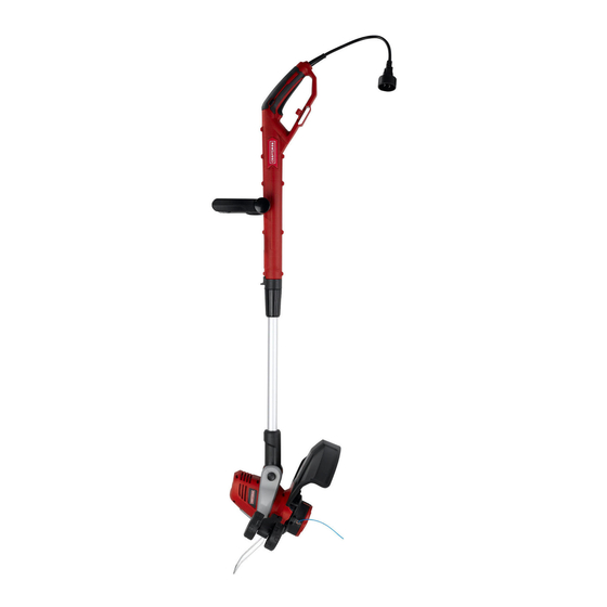
15-Inch 5.5A ELECTRIC
LINE TRIMMER
ORILLADORA ELÉCTRICA
de 15 pulgadas 5.5A
Model No.
151.30383
0
Modelo n
151.30383
Sears Brands Management Corporation, Hoffman Estates, IL 60179 USA
Visit the Craftsman web page: www.craftsman.com
Visite el sitio Web de Craftsman: www.craftsman.com
Save this manual for future reference
Conserve este manual para futura referencia.
WARNING:
To reduce the
risk of injury, the user must read and
understand the operator's manual
before using this product.
ADVERTENCIA:
el riesgo de lesiones, el usuario debe
leer y comprender el manual antes de
utilizar este producto.
Para reducir
Advertisement
Table of Contents

Related Manuals for Craftsman 151.30383


Summary of Contents for Craftsman 151.30383
- Page 1 Sears Brands Management Corporation, Hoffman Estates, IL 60179 USA Visit the Craftsman web page: www.craftsman.com Visite el sitio Web de Craftsman: www.craftsman.com Save this manual for future reference Conserve este manual para futura referencia.
-
Page 2: Table Of Contents
Un producto defectuoso puede reemplazarse por uno nuevo, de manera gratuita, considerando que se presente una PRUEBA DE VENTA. Para conocer la cobertura de la garantía y obtener un reemplazo gratuito, visite el sitio Web www.craftsman.com/ warranty Esta garantía no cubre el carrete del hilo de la orilladora ni la tapa del cabezal del carrete, las cuales son piezas desechables que pueden desgastarse debido al uso normal dentro del periodo de garantía. -
Page 3: Important Safety Instructions
IMPORTANT SAFETY INSTRUCTIONS IMPORTANT SAFETY INSTRUCTIONS ■ Keep hands and feet away from the cutting means at all times and especially when switching on the motor. IMPORTANT! When using electric ■ Take care against injury from any device fi tted for gardening appliance, basic safety precautions should trimming the fi... -
Page 4: Save These Instructions
IMPORTANT SAFETY INSTRUCTIONS MAINTENANCE WARNING! ■ After use, disconnect the machine from the mains - Cutting elements continue to rotate after the motor is and check for damage. switched off; ■ When not in use store the machine out of the reach - Keep extension cords away from cutting elements;... -
Page 5: Symbols
SYMBOLS Some of the following symbols may be used on this product. Please study them and learn their meaning. Proper interpretation of these symbols will allow you to operate the product better and safer. SYMBOL NAME DESIGNATION/EXPLANATION Volts Voltage Amperes Current Hertz Frequency (cycles per second) - Page 6 SYMBOLS The following signal words and meanings are intended to explain the levels of risk associated with this product. SYMBOL SIGNAL MEANING Indicates an imminently hazardous situation, which, if not avoided, will result DANGER in death or serious injury. Indicates a potentially hazardous situation, which, if not avoided, could result WARNING in death or serious injury.
-
Page 7: Features
FEATURES PRODUCT SPECIFICATIONS Voltage..............................120V~ 60Hz Current.................................5.5 AMP Revolutions Per Minute ..........................7300 rpm Line Diameter ......................... 0.065 inch (1.65 mm) Feed System ........................... Dual Line Auto Feed Cutting Width ..............................15 inch Weight ............................6.06 lbs (2.75 kg) AUXILIARY HANDLE KNOW YOUR LINE TRIMMER See Figure 1. -
Page 8: Electrical Information
ELECTRICAL INFORMATION WARNING! GROUNDING INSTRUCTIONS To avoid electrical hazards, fi re hazards, or damage to the tool, use proper circuit IN THE EVENT OF A MALFUNCTION OR protection. Your line trimmer is wired at the factory for BREAKDOWN, grounding provides the path of least 120 v operation. -
Page 9: Assembly
ASSEMBLY UNPACKING FITTING THE AUXILIARY HANDLE See Figure 5-6. This product requires assembly. ■ Loosen and remove the bolt from the handle. ■ Carefully remove the product and any accessories from the box. Make sure that all items listed in the ■... -
Page 10: Operation
OPERATION STARTING/STOPPING THE TRIMMER USING THE FLOWER GUARD See Figure 10-11. See Figure 14. ■ Attach the outlet end of an extension cord to the plug NOTE: The fl ower guard provides a visual indicator of on the rear of the line trimmer. the maximum reach of the trimming line. -
Page 11: Care And Maintenance
CARE AND MAINTENANCE LINE REPLACEMENT Your line trimmer has been designed to operate over a long period of time with a minimum of maintenance. See Figure 19. Continuous satisfactory operation depends upon proper ■ Unplug the line trimmer. tool care and regular cleaning. ■... -
Page 12: Troubleshooting
TROUBLESHOOTING If your line trimmer does not seem to operate properly, WARNING! Before proceeding, switch off fi rst consult the Troubleshooting Table below. and unplug. If the solution to your trimmer problem is not found in the Troubleshooting information, take the trimmer to a qualifi... - Page 13 CRAFTSMAN 15-inch LINE TRIMMER – MODEL NUMBER 151.30383 The model number will be found on a label attached to the motor housing. TO PURCHASE REPLACEMENT PARTS, CALL 1-888-331-4569 13 ― English...
- Page 14 CRAFTSMAN 15-inch LINE TRIMMER – MODEL NUMBER 151.30383 The model number will be found on a label attached to the motor housing. TO PURCHASE REPLACEMENT PARTS, CALL 1-888-331-4569 ITEM NO. PART NO. DESCRIPTION GT80FM.50.00.X1.01 Main Handle Assembly WODQ10.01.11 Switch TOTHYY.16.08 Spring GE50DC.10.01...
- Page 15 See this section for all of the figures referenced in the operator’s manual. Consulte esta sección para ver todas las figuras mencionadas en el manual del usuario. Fig. 1 A - Main Handle (Manilla principal) I - Telescopic Shaft (Eje telescópico) B - Safety Switch (Interruptor de seguridad) J - Motor Housing (Carcasa del motor) C - ON/OFF Switch Trigger (Gatillo interruptor de encendido/...
- Page 16 Fig. 2 Fig. 5 Fig. 3 Fig. 6 A - Safety Guard (Protección de seguridad) A - Bolt (Perno) Fig. 4 Fig. 7 A - Screw (Tornillo) A - Edging Wheel (Rueda orilladora) B - Screw Hole (Orificio del tornillo)
- Page 17 Fig. 8 Fig. 9 Fig. 10 Fig. 11 A - Plug (Enchufe) A - Safety Switch (Interruptor de seguridad) B - Cord Retainer (Retén del cable) B - Switch Trigger (Gatillo interruptor) Fig. 12 Fig. 13 A - Pivot Button (Botón del pivote) B - 7 Positions (7 posiciones)
- Page 18 Fig. 14 Fig. 15 Fig. 16 Fig. 18 A - Spool Cover (Tapa del carrete) E - Slots (Ranuras) B - Spool (Carrete) F - Line Head (Cabezal de hilo) C - Tabs (Pestañas) G - Line Cut-Off Blade D - Eyelets (Ojales) (Hoja de corte de hilo) Fig.
-
Page 19: Importantes Instrucciones De Seguridad
INSTRUCCIONES DE SEGURIDAD IMPORTANTES INSTRUCCIONES DE SEGURIDAD IMPORTANTES corte en todo momento y especialmente al encender el motor. IMPORTANTE Al utilizar el producto de ■ Tenga cuidado de no lesionarse con los dispositivos equipados para recortar el largo del fi lamento. Tras jardinería eléctrico, se deben seguir siempre las extender el nuevo hilo de corte, devuelva siempre precauciones de seguridad básicas a fi... -
Page 20: Guarde Estas Instrucciones
INSTRUCCIONES DE SEGURIDAD IMPORTANTES MANTENIMIENTO ¡ADVERTENCIA! ■ Luego de usar, desconecte la máquina de la - Los elementos cortantes siguen girando después de alimentación y verifi que que no haya recibido daños. que el motor se detiene. ■ Cuando no la esté usando, guarde la máquina lejos - Mantenga los alargadores alejados de los elementos del alcance de los niños. -
Page 21: Símbolos
SÍMBOLOS Algunos de los siguientes símbolos podrían aparecer en este producto. Estúdielos y aprenda su signifi cado. Una interpretación correcta de estos símbolos le permitirá utilizar el producto mejor y de forma más segura. SÍMBOLO NOMBRE NOMBRE/EXPLICACIÓN Volts Voltaje Amperes Corriente Hertz Frecuencia (ciclos por segundo) -
Page 22: Símbolos
SÍMBOLOS Las siguientes palabras y signifi cados están diseñados para explicar los niveles de riesgo asociado a este producto. SÍMBOLO SEÑAL SIGNIFICADO Indica una situación peligrosa inminente, la cual, de no evitarse, causará PELIGRO la muerte o lesiones severas. Indica una situación potencialmente peligrosa, la cual, de no evitarse, ADVERTENCIA podría causar la muerte o lesiones severas. -
Page 23: Características
CARACTERÍSTICAS ESPECIFICACIONES DEL PRODUCTO Voltaje ..............................120V~ 60Hz Corriente ..............................4,2 AMP Revoluciones por minuto ...........................8300 rpm Diámetro del hilo........................0,065 inch (1,65 mm) Sistema de alimentación ................Alimentación automática con hilo doble Ancho de corte ............................ 13 pulgadas Peso ............................. 2,25 kg (5,51 lbs) MANILLA AUXILIAR CONOZCA SU ORILLADORA Consulte la Figura 1. -
Page 24: Información Eléctrica
INFORMACIÓN ELÉCTRICA ■ No la utilice en zonas húmedas ni mojadas ni la ¡ADVERTENCIA! Para evitar peligros exponga a la lluvia. eléctricos, peligros de incendio o daños a la herramienta, utilice una protección de circuitos INSTRUCCIONES PARA LA TOMA A TIERRA adecuada. -
Page 25: Armado
ARMADO DESEMBALAJE CÓMO INSTALAR LA MANILLA AUXILIAR Consulte la Figura 5-6. Este producto requiere armado. ■ Suelte y saque el perno desde la manilla. ■ Con cuidado, extraiga el producto y sus accesorios desde la caja. Asegúrese de que todos los elementos ■... -
Page 26: Funcionamiento
FUNCIONAMIENTO CÓMO ENCENDER/DETENER LA ORILLADORA Cuando el protector para fl ores se desliza hacia abajo, se puede usar como una guía para conocer la distancia Consulte la Figura 10-11. hacia las plantas, postes y rejas cercanas. ■ Inserte el extremo de salida de un alargador en el enchufe de la parte posterior de la orilladora. -
Page 27: Cuidado Y Mantenimiento
CUIDADO Y MANTENIMIENTO CAMBIO DEL HILO Su orilladora ha sido diseñada para funcionar durante un largo periodo de tiempo, con un mínimo de Consulte la Figura 18. mantenimiento. La operación continua satisfactoria ■ Desenchufe la orilladora. depende de un cuidado adecuado de la herramienta y ■... -
Page 28: Resolución De Problemas
RESOLUCIÓN DE PROBLEMAS Si su orilladora no funciona correctamente, consulte ¡ADVERTENCIA! Antes de proceder, primero la siguiente tabla de resolución de problemas. apague y desenchufe. Si la solución al problema de su orilladora no aparece en la información de resolución de problemas, lleve la orilladora con un concesionario de servicio califi... - Page 29 ORILLADORA CRAFTSMAN DE 15 PULGADAS, MODELO NÚMERO: 151.30383 El número de modelo se encuentra en la etiqueta adjunta a la carcasa del motor. PARA ADQUIRIR PIEZAS DE REPUESTO, LLAME AL 1-888-331-4569 13 ― Español...
- Page 30 ORILLADORA CRAFTSMAN DE 15 PULGADAS, MODELO NÚMERO: 151.30383 El número de modelo se encuentra en la etiqueta adjunta a la carcasa del motor. PARA ADQUIRIR PIEZAS DE REPUESTO, LLAME AL 1-888-331-4569 N° DE N° DE PIEZA DESCRIPCIÓN CANT. ARTÍCULO GT80FM.50.00.X1.01 Conjunto de piezas de la manilla principal WODQ10.01.11...
- Page 31 Para respuestas a preguntas o problemas, y ordenar piezas o pedir servicio para la reparación de su equipo. To help us help you, register your product at www.craftsman.com/registration Para poderte ayudar mejor, registra tu producto en www.craftsman.com/registration Join the Craftsman Club today!
Need help?
Do you have a question about the 151.30383 and is the answer not in the manual?
Questions and answers