Table of Contents
Advertisement
Quick Links
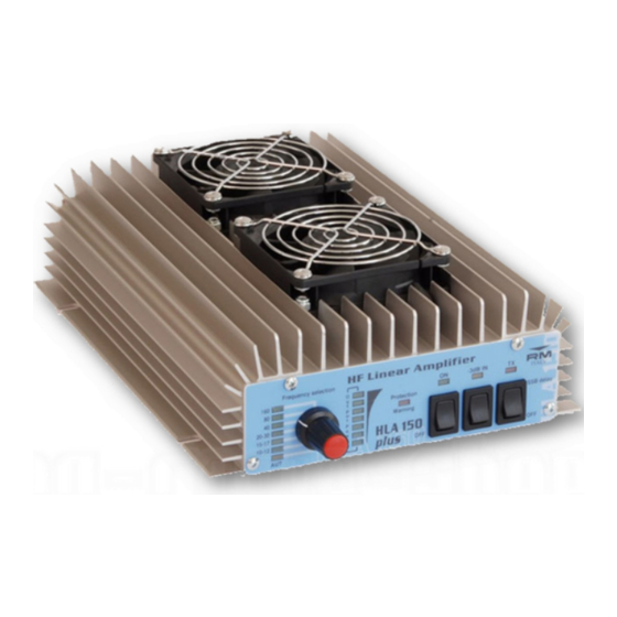
HLA 150plus
HF Broadband 1.8—30 Mhz Linear Amplifier
The HLA150 is a 12VDC HF broadband linear amplifier suitable for use in the range from 1.8
to 30 MHz with a maximum output of 150W (Av. power) with a maximum input drive of 10W,
it has been designed to be used with transceivers with 10W outputs but can be used equally well
with any transceiver capable of producing 1 to 10W output. It uses 2 RF power transistors in a
parallel push pull circuit biased in class AB. There are 6 Low Pass Filters with cut-off frequen-
cies of 3,4,5,8,15,22 and 31Mhz that greatly reduce unwanted harmonic output to acceptable
levels that may be selected manually or automatically. It features a microprocessor that con-
trols all of the functions of the amplifier and its protection circuits. Protection is provided for
excessive input power, excessive load VSWR and excessive heat sink temperature. The ampli-
fier may be used either in a mobile / portable or fixed station installation.
Specifications:
Operation Frequency:
Modulation Types:
Transistor:
Power Supply:
Input Fuse (Internal):
Input RF Power:
Output RF Power (max):
Maximum bypass power (Amplifier off): 100W
Input SWR:
Output SWR Maximum:
WARNING:
Before using this product please read carefully all of
the information in this manual or at least the quick start guide!!! To avoid dam-
age or incorrect operation this is extremely important!!!
1.8—30 MHz (160m to 10m bands)
SSB,CW,AM, FM, data etc (All narrowband modes)
2 x M/A Com MRF455
13VDC+/- 1V 30A
2x12.5A (5x20mm Fast)
1-10W (All modes)
(150W)
1.1—1.5:1
2.5:1
Quick Start Guide:
A more complete guide to the installation is featured later
1.
Connect the input RTX connector to transceiver with 50 Ohm patch
cable
2.
Connect the ANT Output of the Amplifier to SWR Bridge / ATU (If
required), and then the Antenna
3.
Connect the Amplifier DC power Cables to a suitable 13VDC (± 1V)
Power Supply or Auto Battery
4.
Connect PTT cable if required to the transceivers PTT OUTPUT,
(The Amplifier may be used without this connected. PTT is Active
Low and only becomes active after the first transmission)
5.
Set front panel filter selector (2) to Auto
6.
Make sure that the Amplifier is switched off
7.
Adjust the Transceivers output RF power to 8W (10W max) if it is
capable of more than 10W output
8.
If the antenna requires tuning this must be done before the Ampli-
fier is switched on!!
9.
Switch on the Amplifier and start operating
10.
Check that the antenna VSWR is acceptable with the amplifier in
use. Any large increase in VSWR indicates that the Antenna or ATU
is not suitable for the power being used. Operation should be halted
immediately to avoid damage to the Amplifier / Radio / ATU etc.
**** The amplifier must not be used whilst the antenna is being
tuned by either a manual or Automatic ATU *****
***** Automatic ATU's must be placed in standby after the antenna
has been tuned such that they cannot start another tuning cycle
whilst the amplifier is in use*****
Advertisement
Table of Contents

Related Manuals for RM HLA 150 plus


Summary of Contents for RM HLA 150 plus
-
Page 1: Quick Start Guide
Quick Start Guide: HLA 150plus A more complete guide to the installation is featured later HF Broadband 1.8—30 Mhz Linear Amplifier Connect the input RTX connector to transceiver with 50 Ohm patch cable Connect the ANT Output of the Amplifier to SWR Bridge / ATU (If required), and then the Antenna Connect the Amplifier DC power Cables to a suitable 13VDC (±... -
Page 2: Front And Rear Panel Description
Installation: Front and Rear Panel Description Unpack the amplifier from it’s shipping carton and inspect for any signs of damage. The ampli- fier should be installed (either fixed or mobile installation), in a place that allows good ventila- tion and provides a suitable base to support it. Failure to allow for reasonable ventilation will cause the amplifier to overheat and shutdown prematurely. - Page 3 The cross sectional area of the cables used to connect the amplifier to the PSU should not be The protection circuit for excessive input power should not be regarded as a 100% protection ² for all levels of input power. Up to about 50W the circuit will work very effectively and will less than 6mm or 10 AWG They should also be kept as short as practicably possible to avoid...
- Page 4 should be less than 1.5:1. Less than 2.0:1 is acceptable but some reduction in power may be Protection: seen and the amplifier will work less efficiently and generate more heat. At about 2.5:1 the am- plifier will signal an alarm and enter protection. A power reset should be performed and the Excessive Heat sink temperature: amplifier should not be used again until the VSWR has been reduced.
Need help?
Do you have a question about the HLA 150 plus and is the answer not in the manual?
Questions and answers