
Related Manuals for Hitachi N 5024A


Summary of Contents for Hitachi N 5024A
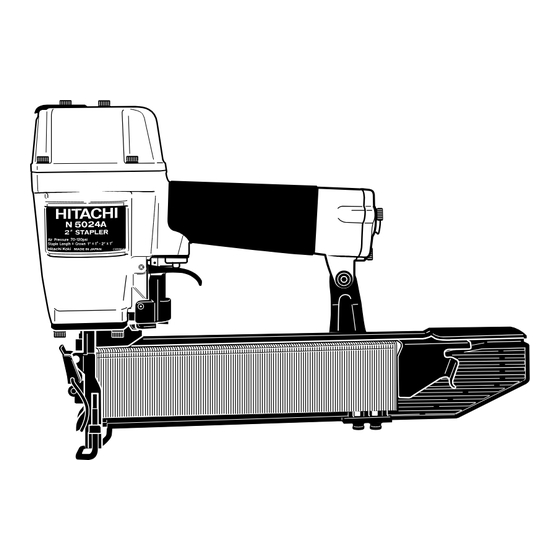
- Page 1 MODEL N 5024A Hitachi Power Tools TECHNICAL DATA STAPLER N 5024A SERVICE MANUAL LIST No. E014 Sep. 2003 SPECIFICATIONS AND PARTS ARE SUBJECT TO CHANGE FOR IMPROVEMENT...
- Page 2 REMARK: Throughout this TECHNICAL DATA AND SERVICE MANUAL, a symbol(s) is(are) used in the place of company name(s) and model name(s) of our competitor(s). The symbol(s) utilized here is(are) as follows: Competitors Symbols Utilized Company Name Model Name PW-2” SENCO PASLODE 3200-W16 450S2...
-
Page 3: Table Of Contents
10-3. Disassembly and Reassembly of the Control Valve Section ............. 22 10-4. Disassembly and Reassembly of the Driving Section and the Magazine Section ..... 24 11. INSPECTION AND CONFIRMATION AFTER REASSEMBLY ..........25 12. STANDARD REPAIR TIME (UNIT) SCHEDULES ..............26 Assembly Diagram for N 5024A... -
Page 4: Product Name
Primary differences from the Model N 5008AC are described below. (1) The weight of the Model N 5024A is 2.1 kg (4.7 lbs.) and it is lighter than our competitors, R, Y and P, thanks to the adoption of the plastic magazine. The staple shoulder sliding portion of the magazine is wear-resistant. -
Page 5: Specifications
5. SPECIFICATIONS 5-1. Specifications N 5024A Model Driving system Reciprocating piston type 5 -- - 8.5 kgf/cm (70 -- - 120 psi, 4.9 -- - 8.3 bar) (Gauge pressure) Operating pressure Driving speed Min. 3 staples/sec. Weight 2.1 kg (4.4 lbs.) -
Page 6: Staple Selection
5-2. Staple Selection The Model N 5024A utilizes medium crown staples, gauge #16, 1" width crown collated by adhesive. Applicable staple dimensions are shown below. CAUTION: Ensure that staples are as specified in Fig. 1. Other gauge staples and other crown width staples will cause clogging of staples and subsequent damage to the stapler. -
Page 7: Staple Driving Force
For example, when driving a staple of 50 mm length (2") into a workpiece of hemlock with the Model N 5024A, a pressure of about 7.7 bar (7.8 kgf/cm , 111 psi) allows the stapler to drive the staple flush with the wood surface. -
Page 8: Comparisons With Similar Products
--- 5 ---... -
Page 9: Precautions In Sales Promotion
7. PRECAUTIONS IN SALES PROMOTION In the interest of promoting the safest and most efficient use of the Model N 5024A Stapler by all of our customers, it is very important that at the time of sale the salesperson carefully ensures that the buyer seriously recognizes the importance of the contents of the Handling Instructions, and fully understands the meaning of the precautions listed on the Warning Label attached to each tool. -
Page 10: Related Laws And Regulations
7-3. Related Laws and Regulations As nailers and staplers are designed to instantaneously drive nails and staples, there is an ever-present danger of misfiring and subsequent possible serious injury. Accordingly, close attention in handling is absolutely necessary at all times. Carefully ensure that the customer is fully aware of the precautions listed in the Handling Instructions provided with each unit. -
Page 11: Mechanism And Operation Principle
8. MECHANISM AND OPERATION PRINCIPLE 8-1. Mechanism As illustrated in Fig. 3, the Model N 5024A can be generally divided into four sections: output section, control valve section, driving section and magazine section. The driving section (nose and piston) and the magazine section have been newly designed though its basic construction is the same as that of the Model N 5008AC (valve section is common to the Model N 5008AC). -
Page 12: Operation Principle
8-2. Operation Principle The operation of the Model N 5024A is illustrated and described in Fig. 4 through 7. The circled numbers in the descriptions correspond to the item numbers shown in the mechanism illustrated in Fig. 3. In Fig. 5 and Fig. 7, read the descriptions in alphabetical order. - Page 13 Compressed air is applied Although air pressure is applied to both the to the upper side of the upper and lower sides of the cylinder, the Exhaust Valve < 2 >, forcing cylinder is forced downward due to the larger it downward and closing Cylinder ring effective area of the upper side.
- Page 14 Air pressure is applied in the shaded areas in the illustration, and each component is held in the position illustrated. If the operator's grip is loosened, air will leak. As there is no o-ring installed here, a very small amount of air will leak from the slight clearance between the components.
- Page 15 The air pressure on the upper surface of the Exhaust Valve < 2 > is released, and the exhaust valve is pushed upward by the air pressure within the cylinder. This opens the Exhaust Vent < 3 >, and the air pressure in the cylinder is discharged from the nailer.
-
Page 16: Troubleshooting Guide
9. TROUBLESHOOTING GUIDE 9-1. Troubleshooting and Correction Possible cause Problem Inspection method Remedy : most-common cause) 1) Staples <Staples> cannot The magazine is not loaded Check if the magazine is Use specified staples. be driven. with specified genuine normally loaded with staples. - Page 17 Possible cause Problem Inspection method Remedy : most-common cause) See item 1). See item 1). Staples are not fully fed into 2) Staples bent the injection port. while being driven. See item 1). See item 1). Unspecified staples used. Replace the part. Check if the driver blade tip Driver blade worn.
-
Page 18: Possible Causes And Correction Of Air Leakage
9-2. Possible Causes and Correction of Air Leakage Air leakage repair location --- 15 ---... - Page 19 Inspection priorities: In the table below, possible causes of air leakage and their repair procedures are marked in accordance with the likelihood of possible failure. (1) First priority items are marked with an asterisk ( ). (2) Second priority items (seal portions) are marked with a double circle ( (3) Remaining items are marked with a single circle ( ).
-
Page 20: Disassembly And Reassembly
Apply grease (Nippeco SEP-3A, Code No. 930035) to the O-rings and O-rings' sliding portions. When installing the O-rings, be careful not to damage the O-rings and prevent dirt entry. Oil required: Hitachi pneumatic tool lubricant 1 oz (30 cc) oil feeder (Code No. 877153) 4 oz (120 cc) oil feeder (Code No. -
Page 21: Disassembly And Reassembly Of The Output Section
10-2. Disassembly and Reassembly of the Output Section (1) Piston [10], Cylinder [14] and the related parts Tool required: Hexagonal bar wrench (4 mm) (a) Disassembly (See Figs. 8, 9 and 10.) Remove the four Hex. Socket Hd. Bolts M5 x 20 [3], and take off the Exhaust Cover [4]. The Piston [10] can then be taken out. - Page 22 Piston [10] Cylinder Guide [18] Cylinder Plate [13] Cylinder [14] Body Ass'y Cylinder Ring [15] [21] Fig. 10 Piston [10] Fig. 11 --- 19 ---...
- Page 23 (2) Head Cap Ass'y [8], Exhaust Valve [7] and the related parts (See Fig. 12.) Tool required: Hex. Socket Hd. Bolt M5 x 25 [1] Hexagonal bar wrench (4 mm) (a) Disassembly Top Cover [2] As described in paragraph 10-2-(1), remove the Exhaust Hex.
- Page 24 Body Ass'y [21] Piston Bumper [23] Valve Guard Bumper Sheet [24] [45] Handle Arm [69] Roll Pin Gasket (A) [25] D3 x 45 Nylon Nut M5 [39] [46] Nose [26] Nylock Hex. Socket Hd. Bolt M5 x 16 [27] Guide Plate [28] Hex.
-
Page 25: Disassembly And Reassembly Of The Control Valve Section
10-3. Disassembly and Reassembly of the Control Valve Section Tools required: Roll pin puller (3 mm (0.118") dia.) Flat-blade screwdriver (a) Disassembly (See Fig. 14.) Remove the driving section and the magazine section as described in section 10-2-(3). With the roll pin puller (3 mm (0.118") dia.), take out the Roll Pin D3 x 30 [68], and remove the Trigger [67], Trigger Plunger [66] and Plunger (B) [60]. - Page 26 Plunger (A) [56] Plunger (B) [60] Trigger [67] Safety Bolt [49] Pushing Lever [51] Valve Guard [45] Guard [36] Nut M5 [50] Adjuster [52] Nose [26] Pushing Lever (A) [54] Fig. 15 Adjustment of safety bolt --- 23 ---...
-
Page 27: Disassembly And Reassembly Of The Driving Section And The Magazine Section
10-4. Disassembly and Reassembly of the Driving Section and the Magazine Section Tools required Hexagonal bar wrench (4 mm) Flat-blade screwdriver with small tip (a) Disassembly (See Fig. 16.) Perform disassembly according to 10-2-(3) to remove the Nose [26], Guide Plate [28] and the magazine section. -
Page 28: Inspection And Confirmation After Reassembly
(b) Reassembly Disassembly procedures should be followed in the reverse order. Note the following points. Apply grease on the sliding portions of the Pushing Lever [51], Sleeve [37] and Nose [26]. Insert the pointed end of the Hinge Pin [76]. Mount the Cover Spring [72] facing the longer arm side toward the Magazine Ass'y [77] as shown in Fig. -
Page 29: Standard Repair Time (Unit) Schedules
12. STANDARD REPAIR TIME (UNIT) SCHEDULES Variable 60 min. MODEL Fixed Work Flow N 5024A Top Cover Nose Exhaust Cover Blade Guide Gasket (B) Magazine Ass'y Gasket (C) Magazine Exhaust Valve Cover Head Cap Ribbon Spring Staple Feeder General Assembly... - Page 30 Hitachi Power Tools LIST NO. E014 PNEUMATIC TOOL PARTS LIST STAPLER 2003 • • Model N 5024A (E1)
- Page 31 PARTS N 5024A ITEM CODE NO. DESCRIPTION REMARKS USED 949-662 HEX. SOCKET HD. BOLT M5X25 (10 PCS.) 876-179 TOP COVER 949-757 HEX. SOCKET HD. BOLT M5X20 (10 PCS.) 877-917 EXHAUST COVER 876-176 GASKET (B) 876-178 GASKET (C) 878-417 EXHAUST VALVE 877-129 HEAD CAP ASS’Y...
- Page 32 PARTS N 5024A ITEM CODE NO. DESCRIPTION REMARKS USED 884-355 ADJUSTER 881-765 RATCHET SPRING 884-354 PUSHING LEVER (A) 875-643 PLUNGER SPRING 878-542 PLUNGER (A) 877-705 PLUNGER O-RING 875-638 O-RING (S-12) 877-880 VALVE BUSHING 877-882 PLUNGER (B) 878-734 VALVE PACKING 875-645 URETHANE BALL (C) D7.14...
- Page 33 N 5024A STANDARD ACCESSORIES ITEM CODE NO. DESCRIPTION REMARKS USED 944-458 HEX. BAR WRENCH 4MM 875-769 SAFETY GLASSES 882-413 CAUTION TAG 882-414 LEAFLET OPTIONAL ACCESSORIES ITEM CODE NO. DESCRIPTION REMARKS USED 876-762 SEQUENTIAL TRIP MECHANISM KIT 881-768 GRIP TAPE (A)
Need help?
Do you have a question about the N 5024A and is the answer not in the manual?
Questions and answers