Table of Contents
Advertisement
ELECTRIC & GAS DRYER
SERVICE MANUAL
CAUTION
READ THIS MANUAL CAREFULLY IN ORDER TO
PROPERLY DIAGNOSE PROBLEMS AND TO SAFELY
PROVIDE QUALITY SERVICE ON THESE DRYERS.
DGS2028EKD DGS2038EKD DGS1828EKD DGS1838EKD
DGS1858EKD DGS1818EKD DES2038EKD
DLE1101W
DLG1102W
U.S.A Website: http://us.lgservice.com
Canadian Website: http://lg.ca
Advertisement
Table of Contents

Related Manuals for LG DGS2028EKD


Summary of Contents for LG DGS2028EKD
- Page 1 U.S.A Website: http://us.lgservice.com Canadian Website: http://lg.ca ELECTRIC & GAS DRYER SERVICE MANUAL CAUTION READ THIS MANUAL CAREFULLY IN ORDER TO PROPERLY DIAGNOSE PROBLEMS AND TO SAFELY PROVIDE QUALITY SERVICE ON THESE DRYERS. DGS2028EKD DGS2038EKD DGS1828EKD DGS1838EKD DGS1858EKD DGS1818EKD DES2038EKD DLE1101W DLG1102W...
-
Page 2: What To Do If You Smell Gas
IMPORTANT SAFETY NOTICE WARNING ! To avoid personal injury, disconnect power before servicing this product. If electrical power is required for diagnosis or test purposes, disconnect the power immediately after performing the necessary checks. To reduce the risk of personal injury, adhere to all industry recommended safety procedures including the use of long sleeved gloves and safety glasses. -
Page 3: Table Of Contents
CONTENTS 1. SPECIFICATIONS ....................... 4 2. FEATURES AND BENEFITS ....................6 3. INSTALLATION INSTRUCTIONS ..................6 4. DRYER CYCLE PROCESS ..................... 9 5. COMPONENT TESTING INFORMATION ................10 6. MOTOR DIAGRAM AND SCHEMATIC ................13 7. WIRING DIAGRAM ......................14 8. FLOW SENSOR FUNCTION ..................... 15 8-1. -
Page 4: Specifications
SPECIFICATIONS Name: Electric and Gas Dryer Power supply: Refer to the rating label on the dryer. Gas: 120 VAC Electric: 240VAC Size: 27” X 40 ” X 29” (inch) Dryer capacity: IEC 7.3 cu.ft. Weight: 125.5 (Ibs) Specifications are subject to change by manufacturer. CCESSORIES ryer rack (1 each) (Sold Separately : Some Model) - Page 5 DGS2028EKD DGS2038EKD DGS1828EKD DGS1838EKD DGS1858EKD DGS1818EKD REMARK ITEM DES2038EKD DLE1101W DLG1102W Color Blue White / Stainless Silver Material & Top Plate White / Silver / Black Finish Door Trim Chrome ELEC. 120/240V 60Hz (26A)/120/208V 60Hz (23A) POWER SUPPLY 120V/60Hz (11.5A) AC 120V 250W (4.5A)
-
Page 6: Features And Benefits
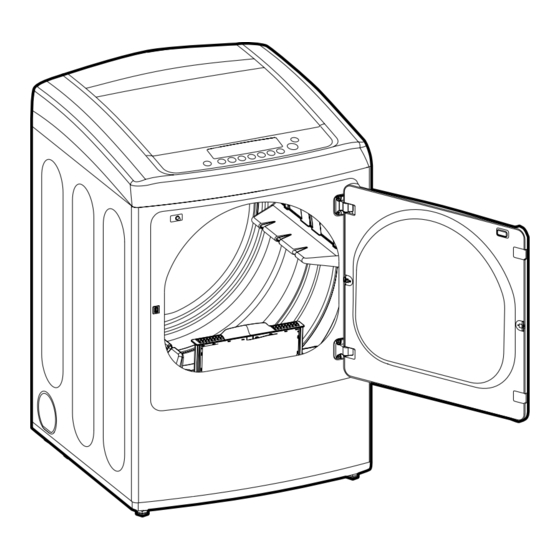
FEATURES AND BENEFITS INSTALLATION INSTRUCTIONS pen the door. Put the dryer rack into Check and be sure that the Hold the dryer rack the drum front of the rack is properly with both hands. seated behind the lint filter. - Page 7 1. Connect the neutral wire (white) of the power Review the following options to determine cord to the center terminal block screw. the appropriate electrical connection for 2. Connect the red and black wires to the left and your home: right terminal block screws.
- Page 8 Connect Gas Supply Pipe (Gas Dryer ONLY) For further assistance, refer to section on Gas Requirements. 1. Make certain your dryer is equipped for use with the 3. Connect to gas supply pipe using a new flexible type of gas in your laundry room. Dryer is equipped stainless steel connector.
-
Page 9: Dryer Cycle Process
DRYER CYCLE PROCESS * Sensor dry: Dry Level is set by users. ** Manual dry: Temperature control is set by users. Default settings can be adjusted by users. -
Page 10: Component Testing Information
COMPONENT TESTING INFORMATION... - Page 11 Component Test Procedure Check result Remark 7. Heater Measure resistance of the following terminal Resistance value: 10 Terminal: 1 (COM) - 2 Resistance value: 10 Terminal: 1 (COM) - 3 Resistance value: 20 Terminal: 2 - 3 8. Thermistor Resistance value: 10 Measure resistance of terminal to terminal Temperature condition:...
- Page 12 Component Test Procedure Check result Remark 13. Outlet Thermostat Measure resistance of terminal • Gas type (Auto reset) to terminal • Gas funnel Open at 203 7°F (95 5°C Resistance value Close at 159 9°F (70 5°C) Continuity < 1Ω •...
-
Page 13: Motor Diagram And Schematic
MOTOR DIAGRAM AND SCHEMATIC NOTE When checking Component, be sure to turn Power off, then do voltage discharge sufficiently. ■ Contact On / Off by Centrifugal Switch Terminal No Remark Mode Resistance Motor 2 ~ 3Ω Motor Heater (Electric Models) STOP Gas Valve (Gas Models) Motor... -
Page 14: Wiring Diagram
WIRING DIAGRAM Label all wires prior to disconnection when servicing controls. Wiring CAUTION errors can cause improper and dangrous operation. Verify proper operation after servicing. ELECTRIC DRYER WIRING DIAGRAM GAS DRYER WIRING DIAGRAM... -
Page 15: Flow Sensor Function
FLOW SENSOR FUNCTION 8-1 Flow sensor This FlowSense function detects the clogging or blocking of ducts. Clogged duct vents or hoses decrease e fficiency in drying clothes. Clogged vents can also cause fire. This function alarms you, when to clean the ducts. When the alarm about duct clogging is on display of the panel, your duct vents should be cleaned by yourself or serviceman. -
Page 16: Installation Test
8-2 Installation test Installation test (Exhaust check) Check the display for results. Once you have completed the installation of the dryer, use this During the two minute test cycle, monitor the FLOW SENSE test to make sure the condition of the exhaust system is adequate display on the control panel. - Page 17 Installation test (Exhaust check) (cont.) Check the Error Code before you call for service Possible Causes Solutions Error Code • Turn off the dryer and call for • Temperature sensor failure service. • Turn off the dryer and call for •...
-
Page 18: Troubleshooting For Flow Sensor Dryer
8-3 Troubleshooting for flow sensor dryer 1. FLOW SENSE indicator light is on Is lint filter full? Clean lint filter before every load Is duct clogged? Check & clean duct. 2. FLOW SENSE indicator light is on and does not disappear. 1. -
Page 19: Diagnostic Test
DIAGNOSTIC TEST 1. This TEST should be used for Factory test /Service test. Do not use this DIAGNOSTIC TEST other than specified. 2. Activating the Heater manually with the Door open may trip the Thermostat attached to the Heater, therefore do not activate it manually. -
Page 20: Test 1 120V Ac Electrical Supply
Test 1 120V AC Electrical supply When measuring power, be sure to wear insulated gloves, to and avoid an Caution electric shock Trouble Symptom No power was applied to controller. (LED, LCD Display off) Measurement Condition With dryer power on; connector linked to controller. •... -
Page 21: Test 2 Thermistor Test - Measure With Power Off
Test 2 Thermistor Test --- Measure with Power Off Disconnect the NA6 connector from the main PCB. •Check all wiring Measure the resistance harness between the NA6-6 (GN) pin connections, and a chassis ground screw. wires and Is the resistance <1 Ω ? ground screws. -
Page 22: Test 3 Motor Test
Test 3 Motor test Before measuring resistance, be sure to turn power off, and do voltage discharge. Caution (When discharging, contact the metal plug of power cord with earth line.) Trouble Symptom Drum will not rotate; no fan will function; no heater will work. Measurement Condition Turn the dryer’s power off, then measure resistance. -
Page 23: Test 4 Moisture Sensor
Test 4 Test 4 Moisture sensor Moisture sensor NOTE: This test has two parts. The best test of the moisture sensing system is done in the diagnostic mode. This FUNCTIONAL TEST will test the sensor bars, wiring harness and PCB operation. If the results of this test are normal, the sensor system and PCB response are normal. -
Page 24: Test 5 Door Switch Test
Test 5 Door switch test NOTE: This test has two parts. The best test of the door switch system is done in the diagnostic mode. This FUNCTIONAL TEST will test the door switch, wiring harness and PCB operation. If the results of this test are normal, the door switch system and PCB response are normal. -
Page 25: Test 6 Heater Switch Test - Electric Type
Test 6 Heater switch test - Electric Type Enter diagnostic mode and • Check power press the START/PAUSE supply. button twice. Measure the voltage between YL3- 3 (WH) and the YL wire on the black tab relay. Is the voltage 240 VAC? Disconnect the YL3, black tab •... -
Page 26: Test 7 Gas Valve Test - Gas Type
Test 7 Test 7 GAS Valve test - Gas Type GAS Valve test - Gas Type Caution When measuring power, be sure to wear insulated gloves, to avoid electric shock. While operating, heating will not work. Trouble Symptom Drying time takes longer Measurement Condition With dryer power on Power on &... -
Page 27: Test 8 Motor Assembly, Dc, Pump
Test 8 Motor Assembly, DC, Pump Before measuring resistance, be sure to turn Power off, and do voltage discharge. Caution (When discharging, contact the metal plug of Power cord with earth line.) Trouble Symptom Degree of Resistance is not in 300°æ30 Ω Measurement Condition Turn the Dryer’s Power Off, then measure resistance. -
Page 28: Change Gas Setting (Natural Gas, Propane Gas)
CHANGE GAS SETTING (NATURAL GAS, PROPANE GAS) Changing orifices and gas valve adjustments improperly can result in an Warning explosion and/or fire. Conversion must be made by a qualified technician. Initially, The burner is set for natural gas at the factory. The propane orifice Natural Gas mode is set. - Page 29 VALVE 1 IGNITER FLAME DETECT VALVE 2...
-
Page 30: Disassembly Instructions
DISASSEMBLY INSTRUCTIONS Disassemble and repair the unit only after pulling out power plug from the outlet. TOP PLATE WARNING! When you disassemble the Dryer, be sure to disconnect the dryer from its electrical supply. Protect your hands and arms from sharp edges when working. -
Page 31: Top Cover
CONTROL PANEL WARNING! When you disassemble the Dryer, be sure to disconnect the dryer from its electrical supply. Protect your hands and arms from sharp edges when working. To reduce the risk of personal injury, adhere to all industry recommended safety procedures including the use of long sleeved gloves and safety glasses. - Page 32 CABINET COVER WARNING! When you disassemble the Dryer, be sure to disconnect the dryer from its electrical supply. Protect your hands and arms from sharp edges when working. To reduce the risk of personal injury, adhere to all industry recommended safety procedures including the use of long sleeved gloves and safety glasses.
-
Page 33: Drum Assembly
TUB DRUM [FRONT] When you disassemble the Dryer, be sure to disconnect the dryer from its electrical supply. Protect your hands and arms from sharp edges when working. To reduce the risk of personal injury, adhere to all industry recommended safety procedures including the use of long sleeved gloves and safety glasses. - Page 34 WARNING ! DRYER EXHAUST CHANGE Before performing this exhaust installation, be sure to disconnect the dryer from its electrical supply. Protect your hands and arms from sharp edges when working inside the cabinet. To reduce the risk of personal injury, adhere to all industry recommended safety procedures including the use of long sleeved gloves and safety glasses.
-
Page 35: Filter Assembly
FILTER ASSEMBLY When you disassemble the Dryer, be sure to disconnect the dryer from its electrical supply. Protect your hands and arms from sharp edges when working. To reduce the risk of personal injury, adhere to all industry recommended safety procedures including the use of long sleeved gloves and safety glasses. -
Page 36: Air Duct
AIR DUCT When you disassemble the Dryer, be sure to disconnect the dryer from its electrical supply. Protect your hands and arms from sharp edges when working. To reduce the risk of personal injury, adhere to all industry recommended safety procedures including the use of long sleeved gloves and safety glasses. -
Page 37: Exploded View
EXPLODED VIEW 12-1. Control Panel and Plate Assembly A115 A215 A120 A130 A110 A150 A570 A210 A213... -
Page 38: Cabinet And Door Assembly
12-2. Cabinet & Door Assembly A800 A610 A600 A320 A330 A315 A314 A313 A500 A325 A510 A310 A131 A545 A520 A540 A430 A410 A440 A470 A475 A450 A420 A430 A400... -
Page 39: Drum And Motor Assembly: Electric Type
12-3-1. Drum & Motor Assembly: Electric Type F200 K400 K120 K100 K140 K130 K251 K250 K310 K320 K340 K336 K225 K222 K335 K330 K221 K224 K230 K360 K250 K210 K620 K550 K560 K610 K350 K251 K540 K240 K530 K510 K520 F140 K655 K660... -
Page 40: Drum And Motor Assembly: Gas Type
April 2012 PRINTED IN KOREA P/No. : MFL62119948...
Need help?
Do you have a question about the DGS2028EKD and is the answer not in the manual?
Questions and answers