Table of Contents
Advertisement
Quick Links
Document
Service
supplémentaire
Manual
nécessaire pour
la maintenance:
Additionally
required Service
Manuals for the
Réf. N°./Part No.
72010-520.90
Complete Service:
1
2
3
4
5
6
7
8
9
TIMER
ON / OFF
SV
0
AV
TIMER
ON/OFF
CHECK
CLEAR
PAL / SECAM
Sous réserve de modifications
Subject to alteration
SERVICE MANUAL
Service
Manual
Sécurité
Safety
Réf. N°./Part No.
72010-800.00
II
II
Printed in Germany
VK 24
0895
GV 505 EURO, GV 506 EURO
GV 515 EURO, GV 535 EURO
GV 5055 EURO
GV 505 EURO
GV 515 EURO
GV 535 EURO
GV 506 EURO
GV 5055 EURO
DAY
START
PROG.
STOP
ON/OFF
1
2
3
5
4
6
8
7
9
RP500
0
VPT
AV
I
Service Manual Réf. N°.
Service Manual Part No.
VIDEO
Btx
Btx
Btx
32700 #
32700 #
32700 #
*
*
*
D
D
D
(77400-614.51 / G.ME 0900 FB)
(77400-613.51 / G.ME 1700 FB)
(77400-605.51 / G.ME 2100 FB)
(77400-624.51 / G.ME 1000 FB)
(77400-633.51 / G.ME 1900 FB)
(75988-010.71)
72010-520.90
72010-520.90
Advertisement
Table of Contents

Related Manuals for Grundig GV 505 EURO


Summary of Contents for Grundig GV 505 EURO
- Page 1 32700 # 32700 # Document Service Service supplémentaire Manual Manual nécessaire pour la maintenance: GV 505 EURO, GV 506 EURO Sécurité Additionally Safety required Service GV 515 EURO, GV 535 EURO Manuals for the Réf. N°./Part No. Réf. N°./Part No. 72010-520.90 Complete Service: 72010-800.00...
-
Page 2: Table Of Contents
Replacement of Tape Deck Components ........5-3 Remplacement d'éléments de la mécanique ........5-3 Réglages ..................5-10 Adjustments ................... 5-10 Vues éclatées et Liste Exploded Views and de pièces détachées ......E-1…E-28 Spare Parts List ........E-1…E-28 1 - 2 GRUNDIG Service... -
Page 3: Composition Des Appareils
Partie générale / General Composition des appareils / Video Recorder Overview Tableau des modules Tableau des équipements Table of Moduls Table of Features GV 505 EURO GV 505 EURO GV 506 EURO GV 506 EURO GV 515 EURO GV 515 EURO... -
Page 4: Appareils De Mesure / Moyens De Maintenance
Ces auxiliaires de maintenance peuvent être obtenus auprès des You can order these test equipments from the Service organization or Stations Techniques Régionales Grundig ou à l'adresse ci-dessous. at the below mentionned adress. We refer to you that these test Une partie de ces auxiliaires de maintenance est disponible dans le equipments are already obtainable on the market. -
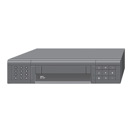
Page 5: Eléments De Commande
Eléments de commande Information: Ce chapitre contient des extraits du mode d'emploi. Pour toutes informations supplémentaires veuillez vous référer au mode d'emploi spécifique à chaque appareil, dont le numéro de référence est indiqué dans la liste de pléces détachées. EXT 1 EXT 1 Touches numériques pour diverses programmations EXT 2... - Page 6 Commutateur pour le choix du niveau Mise en place des piles dans la En un clin d’oeil vidéo télécommande Les touches de la télécommande sont brièvement expliquées sur cette page et sur la page suivante. Touches pour les diverses saisies Pour l’utilisation, reportez-vous au chapitre corre- STOP ¢...
- Page 7 Le guide GRUNDIG de l’utilisateur Régler l’heure et la date Réglage des chaînes sur l’écran du téléviseur Les chaînes télévisées émettent leurs programmes Lorsque le magnétoscope n’est plus relié au sec- sur différentes fréquences / différents canaux. … propose un dialogue entre l’utilisateur et le Préparatifs...
-
Page 8: Abréviations
Réglage des chaînes avec le Trier les chaînes avec la fonction Trier manuellement les chaînes système de recherche-mémori- « selon TV » sation (ATS euro plus) Préparatifs Ce système permet d’ordonner de façon semblable les chaînes du magnétoscope et celles du télévi- Mettez le téléviseur en service. - Page 9 En un clin d’oeil Réglage manuel Préparatifs Alternativement à la saisie des n° de canaux, la fré- quence des chaînes peut être saisie, en appuyant Mettez le téléviseur en service. sur la touche Z VPS (rouge) – L’affichage passe de » CANAL « à » FRÉQUENCE «. Sélectionnez sur le téléviseur le n°...
- Page 10 Optimiser la netteté de l’image Correction de l’image / du son Recherche précise de séquence (Automatic Contour Control Plus) Video Index Such System (VISS) En lecture, le magnétoscope se règle automatique- Correction automatique de l’image / du Ce système permet de trouver rapidement et ment de façon à...
- Page 11 D’un coup d’oeil Serrure électronique Réglage de l’affichage des fonctions (OSD – ON SCREEN Toutes les fonctions peuvent être verrouillées à l’aide de la serrure électronique. DISPLAY) Même une cassette qui a été ultérieurement intro- La durée de l’affichage des fonctions sur l’écran du duite dans le magnétoscope doit rester dans le téléviseur peut être réglée.
- Page 12 Avec cette télécommande, vous pouvez comman- La langue du guide de l’utilisateur peut être modi- Avec cette télécommande vidéo, vous pouvez Commande à distance des deux der d’autres magnétoscopes GRUNDIG, indépen- fiée. également commander des téléviseurs couleur magnétoscopes damment l’un de l’autre.
-
Page 13: Tableaux Des Normes Et Des Canaux
303,25MHz 751,25MHz 311,25MHz 759,25MHz 319,25MHz 767,25MHz 327,25MHz 775,25MHz 335,25MHz 783,25MHz 343,25MHz 791,25MHz 351,25MHz 799,25MHz 359,25MHz 807,25MHz 367,25MHz 815,25MHz 375,25MHz 823,25MHz 383,25MHz 831,25MHz 391,25MHz 839,25MHz 399,25MHz 847,25MHz 407,25MHz 855,25MHz 415,25MHz 423,25MHz 431,25MHz 439,25MHz 447,25MHz 455,25MHz 463,25MHz GRUNDIG Service 1 - 15... - Page 14 719,25MHz 335,25MHz 727,25MHz 343,25MHz 735,25MHz 351,25MHz 743,25MHz 359,25MHz 751,25MHz 367,25MHz 759,25MHz 375,25MHz 767,25MHz 383,25MHz 775,25MHz 391,25MHz 783,25MHz 399,25MHz 791,25MHz 407,25MHz 799,25MHz 415,25MHz 807,25MHz 423,25MHz 815,25MHz 431,25MHz 823,25MHz 439,25MHz 831,25MHz 447,25MHz 839,25MHz 455,25MHz 847,25MHz 463,25MHz 855,25MHz 1 - 16 GRUNDIG Service...
-
Page 15: Instructions Pour La Maintenance
– Pousser les 2 goujons de charnière dans le sens des flèches (Fig. 2). – Ouvrir le volet de façade à moitié et le retirer. Fig. 1 Fig. 2 Fig. 3 Fig. 5 Fig. 4 GRUNDIG Service 1 - 17... - Page 16 …pour des raisons de sécurité (VDE) la protection du modulateur est Carry out the alignment procedures described in chapter 3. remise en place. Effectuer les alignements du chapitre 3. Fig. 7 Fig. 8 Fig. 6 Fig. 9 Fig. 10 Fig. 11 1 - 18 GRUNDIG Service...
- Page 17 (Fig. 14) et débrancher les connecteurs de (Fig. 14). liaison avec les étages électroniques si nécessaire. – Undo the screws (Fig. 14) and unplug the connectors to the electronics if necessary. Fig. 12 Fig. 13 Fig. 14 GRUNDIG Service 1 - 19...
- Page 18 Important changes are indicated by increasing the change code by d'une unité. one. Numéro de commande / Order number TYPE GV 505 EURO Type d'appareil / Type of product Date de fabrication / Production date G.ME 09-00 FB RP 500 Télécommande / Remote Control...
-
Page 19: Fonctions De Service Et Fonctions Spéciales
Compteur d'heures de fonctionnement / Operating Hours Pour des informations plus détaillées, veuillez vous référer au paragraphe For more detailed information please see chapter "1.1.2 Service Test "1.1.2 Affichage du programme test de maintenance sur le magnétoscope". Programme Indication on VCR". GRUNDIG Service 1 - 21... - Page 20 Contact Init / Init switch B: AC, 2V/Div, 0,5s/Div Impulsion tachy d'engagement (FTA) Threading pulse (FTA) Lecture / Play Cassette engagée / Cassette in Engagement / Thread in Cassette "en bas" / Cassette down Index, Rebobinage / Index, wind-rewind 1 - 22 GRUNDIG Service...
- Page 21 Si pendant le fonctionnement de la mécanique il vient à manquer un signal tachymétrique, le magnétoscope cherche à mettre le compar- the VCR tries to move the cassette compartment to the "EJECT" position. timent de cassette en position "EJECT". GRUNDIG Service 1 - 23...
- Page 22 GV 505 EURO) and confirm with G. – Introduire le code d'option "A", voir numéro de l'appareil (par ex."063" pour GV 505 EURO) et confirmer par la touche G. The option code is then indicated on the display for approx. 2s in L'afficheur indique alors pour vérification pendant env.
- Page 23 – Appuyer sur la touche A ou débrancher l'appareil du secteur. recorder from the mains. Lecture Enregistrement Fin de bande Play Record End of Tape Début de bande Rebobinage Rewind Beginning of tape GRUNDIG Service 1 - 25...
- Page 24 – Appuyer sur la touche "CODE" de la télécommande – Introduire le code 4 9 3 4 – Appuyer sur la touche puis sur la touche , ou débrancher l'appareil du secteur. 1 - 26 GRUNDIG Service...
-
Page 25: Alimentation (Osm...)
à travers les diodes, les condensateurs et la charge. GRUNDIG Service 2 - 1... - Page 26 IC7105-(3). This point is the so-called reversal point. The IC supply secondaires. Ainsi celle-ci diminue lorsque la charge augmente. voltage Vcc behaves in the same way as do the secondary voltages. This voltage decreases also along with the increasing load. 2 - 2 GRUNDIG Service...
-
Page 27: Circuit Principal (Ofb2)
IC7101-(12) as a negated pulse. Addition- et d'inversion de phase T7030 / T7031. En outre cette impulsion "POR" ally, this "POR" pulse is routed to the central computer IC7800-(10). est acheminée vers le microcontrôleur principal IC7800-(10). GRUNDIG Service 2 - 3... - Page 28 1913-(15) and pin 8 of the IC7411. The D6402 et le connecteur 1913-(13). Pour la régulation des vitesses, la tachopulses (actual value) are compared in the IC7410 with an 2 - 4 GRUNDIG Service...
-
Page 29: Etage Fi Euro (Fv)
Puis amplifier with synchronous demodulator. The demodulated IF signal il est dirigé vers la démodulation du son FM via le filtre FI F1745-(15). for sound processing is fed out from IC7721-(17). Via the IF filter GRUNDIG Service 2 - 5... -
Page 30: In/Out, Vps (Io)
TV stations have fixed an earlier broad- quence. casting time than originally planned, and that the video recorder is controlled accordingly. 2 - 6 GRUNDIG Service... -
Page 31: Video/Chroma (Vs)
(NL DE EMPHASIS), the noise reduction stage (WHI NOI bruit à fréquences basses qui en résulte est additionnée en opposition CAN) for high-frequency noise voltages and a high-frequency preem- de phases via un filtre d'évaluation avec le signal Y non retardé. Le GRUNDIG Service 2 - 7... - Page 32 VXO and controls the latter accordingly. The (4,433619MHz) est déterminée par le quartz (Q1000) relié aux pins 32 control voltage provided on IC7051-(33) is smoothed by C2004, R3001 et 31. L'étage détecteur enregistrement REC-APC compare la phase 2 - 8 GRUNDIG Service...
-
Page 33: Son Mono / Audio Linéaire (Al)
C2611 le son AMLP est envoyé respectivement via l'interface de switch EP CTL. commutation "IN/OUT" vers le modulateur et l'embase EURO-AV1. En lecture "LP", la commutation de correction de lecture est effectuée par le commutateur EP CTL. GRUNDIG Service 2 - 9... -
Page 34: Circuit Principal Ii (Osio)
T7813 et le généra- transistor stage T7813 and the pulse shaper T7810 / T7811 at teur d'impulsions T7810 / T7811. IC7800-(14). The data fed out at IC7800-(15) is taken via T7812 to contact 10 of the EURO-AV1 socket. 2 - 10 GRUNDIG Service... -
Page 35: Follow Tv (Io)
(FMRV) is taken via the amplifier stage T7018 / T7019 and plug obtenu (FMRV) traverse l'étage d'ampli T7018 / T7019 et par le contact contact 1911-(2) to the head amplifier. 1911-(2) il est acheminé vers l'ampli de têtes. GRUNDIG Service 2 - 11... -
Page 36: Module De Commande (Odcg...)
Lithium batteries must be replaced only by original spare parts d'origine (voir liste de pièces détachées). (see Spare Parts List). Observe the appropriate disposal regulations Les piles au lithium usagées ne doivent pas être jetées. Leur for exhausted lithium batteries. élimination est réglementée. 2 - 12 GRUNDIG Service... -
Page 37: Alimentation (Osm...)
4 9 3 4 et confirmer par la touche G. Cause: Cassette test, tambour de têtes ou défaut technique (par ex. µP) – Appuyer sur la touche "CODE", introduire le code 4 9 3 6 et confirmer par la touche G. GRUNDIG Service 3 - 1... -
Page 38: Etage Fi Euro (Fv)
4 9 3 4 et confirmer par la touche G . trôle Automatique de Contour) plus – Appuyer sur la touche "CODE", introduire le code 4 9 3 8 et confirmer par la touche G . Studio Quality" 3 - 2 GRUNDIG Service... -
Page 39: Son Mono / Audio Linéaire (Al)
– Appuyer sur la touche "CODE", introduire le code 4 9 3 4 et confirmer par la touche G . – Appuyer sur la touche "CODE", introduire le code 4 9 5 0 et confirmer par la touche G . GRUNDIG Service 3 - 3... -
Page 40: Power Supply (Osm...)
Reason: Test cassette, headwheel or technical defect (eg. µC). 4 9 3 4 and press the G button. – Press the button "CODE", enter the code number 4 9 3 6 and press the G button. 3 - 4 GRUNDIG Service... -
Page 41: Frontend (Fv)
4 9 3 4 and press the G button. tic Contour Control) plus – Press the button "CODE", enter the code number 4 9 3 8 and press the G button. Studio Quality GRUNDIG Service 3 - 5... -
Page 42: Test Equipment / Aids
0,715ns by the manufacturer. 4 9 3 4 and press the G button. – Press the button "CODE", enter the code number 4 9 5 0 and press the G button. Frequency Counter: ........... 1101-(1) 3 - 6 GRUNDIG Service... - Page 43 Moteur tambour de têtes Headwheel motor Impuls.de commut. têtes vidéo Head switching pulse Commande sélection de têtes Head select control HSC2 Commutation phase vidéo en configuration mode LP Colour phase switching for LP feature mode GRUNDIG Service 4 - 1...
-
Page 44: Ampli De Têtes
Circuit de signal "Vidéo/Chroma" Signal electronics "Video/Chroma" Vidéo issue du circuit de signal Video from signal electronics OSIO Piste synchro - écriture/lecture write/read CTL-sync WTL/WTLD Tachymètre plateau gauche Wind tacho left WTR/WTRD Tachymètre plateau droit Wind tacho right 4 - 2 GRUNDIG Service... - Page 45 Key Set Unit 8009 (ODCG3) 1102 1201 3112 438 0030 AUDIO VIDEO ODCG ODCG3 ODCG1 ODCG31 L in R in VID in ODCG3/31 ODCG4/41 ODCG5 Display Control Component side 1109 ODCG4 ODCG5 GRUNDIG Service 4 - 3 GRUNDIG Service 4 - 4...
- Page 46 Circuits imprimés et schémas électriques / Layout of PCBs and Circuit Diagrams Synoptique des ciruits imprimés (Analogique) / Block Circuit Diagram (Analog) FOLLOW TV PART only for Megalogic (OSIO or OVIO) FOLLOW TV ACC+1 (DE) Automatic Contour ACC+2 (DE) Control 4 - 5 GRUNDIG Service 4 - 6 GRUNDIG Service...
- Page 47 Circuits imprimés et schémas électriques / Layout of PCBs and Circuit Diagrams ACC+1 (DE) ACC+2 (DE) GRUNDIG Service 4 - 7...
- Page 48 Circuits imprimés et schémas électriques / Layout of PCBs and Circuit Diagrams 4 - 8 GRUNDIG Service...
- Page 49 Circuits imprimés et schémas électriques / Layout of PCBs and Circuit Diagrams Circuits imprimés et schémas électriques / Layout of PCBs and Circuit Diagrams Synoptique des ciruits imprimés (Digital) / Block Circuit Diagram (Digital) only for Megalogic GRUNDIG Service 4 - 9 GRUNDIG Service 4 - 10...
- Page 50 TL431CLP 7210 SOC1012T HOT CIRCUIT , BE CAREFUL AND USE AN ISOLATION TRANSFORMER WHEN SERVICING COLD GND DO NOT OPERATE WITHOUT CASE HOT GND CAUTION : LETHAL POTENTIALS AT PRIMARY 4 - 11 GRUNDIG Service 4 - 12 GRUNDIG Service...
- Page 51 6116 F 7 6135 G 8 6136 H 8 6201 B12 6203 C12 6204 D12 6206 E13 6207 B13 6210 H12 6211 A16 7105 E 4 7135 F 9 7210 J10 GRUNDIG Service 4 - 13 GRUNDIG Service 4 - 14...
- Page 52 6 5 7 4 6 5 7 0 6 5 7 5 7 5 4 0 6 5 7 2 1 5 0 1 9 0 7 6 1 9 1 7 4 - 15 GRUNDIG Service 4 - 16 GRUNDIG Service...
- Page 53 7 5 7 2 7 5 7 3 7 5 5 1 3 9 0 2 3 9 4 6 7 5 7 1 3 5 7 5 3 5 7 8 GRUNDIG Service 4 - 17 GRUNDIG Service 4 - 18...
- Page 54 3500 8001 8002 3600 6104 9001 WDS.3 8203 101 74512 3500 RECP 3502 0004 7105 INIT 0003 TCRT5000 SVHS STRIP 8004 3501 1502 to CMO RECP STRIP 8003 7106 S298P 4 - 19 GRUNDIG Service 4 - 20 GRUNDIG Service...
- Page 55 ...V MEASURED IN PLAYBACK MODE 7410 F15 ...V MEASURED IN RECORD MODE 7411 L 8 7412 M21 7413 A10 To Power Supply OSM4 1901 To ODC 1105 To Head Amplifier 1930 To ODC 1101 GRUNDIG Service 4 - 21 GRUNDIG Service 4 - 22...
- Page 56 5VSWA ...V MEASURED IN PLAYBACK MODE ...V MEASURED IN RECORD MODE PAL BG/SEC L FROM DE H = PAL BG TO DE L = SEC L 5VSWA +33V FROM DE 4 - 23 GRUNDIG Service 4 - 24 GRUNDIG Service...
- Page 57 5740 I15 6722 F 9 6723 F 9 5VSWA 6825 C 9 6826 C 9 7720 E12 7721 D16 7723 E21 7724 J12 7725 G20 7726 A15 7727 I 8 7823 D 9 7824 C 9 GRUNDIG Service 4 - 25...
- Page 58 IOFP IOFP INT/pin10 INT/pin10 2544 not used 3546 5VPB 5VPB From VS 8SC2 8SC2 FOME FOME From DE IMODON IMODON DATD1 DATD1 From DE 5VSWA CLKD1 CLKD1 5VSWA From DE -28V -28V From DE GNDA 4 - 26 GRUNDIG Service...
- Page 59 7571 E 5 1,2V FBAS AQUISITION INTERFACE 3541 7572 F 4 5,3V 7573 F 3 100E PDC-Option TIMING 5,2V DAVN GNDA GNDA GNDA GNDA GNDA GNDA GNDA VPS/PDC delete for TXT GRUNDIG Service 4 - 27 GRUNDIG Service 4 - 28...
- Page 60 DTC124EK 5VSWAS BAND ACC+1 ACC+ norm for ACC+ only 2.5V LM339 schl 2,5V 7035 s.gut 1,5V 2.5V ...V MEASURED IN PLAYBACK MODE for ACC+ only ...V MEASURED IN RECORD MODE 4 - 29 GRUNDIG Service 4 - 30 GRUNDIG Service...
- Page 61 3056 K18 3057 L18 3068 I31 3069 I30 3070 A14 3071 B14 3072 B16 3073 N19 3074 N19 3075 L19 3076 L19 Record 3079 N19 3080 L19 Playback 3081 M19 3085 N14 3901 C26 3935 B20 GRUNDIG Service 4 - 31...
- Page 62 1918 G15 2604 H 7 2609 H 5 2614 D 6 2619 A12 2624 G13 2629 H11 2652 E 3 3604 H 7 3609 G 9 3614 F 3 3619 B13 3625 A11 3634 G11 3650 C 6 5602 F14 7602 D 9 7609 B13 1919 H15...
- Page 63 7 8 1 3 7 1 0 5 7 1 0 4 2 8 0 1 2 8 3 0 3 8 3 1 7 8 2 2 3 8 5 2 3 8 5 3 GRUNDIG Service 4 - 33...
- Page 64 GNDD 7802 For Megalogic only 12MHz IC-8KX8-SRAM 3810 3811 7810 BC848B 7811 GNDD BC848B GNDD GNDD 3815 GNDD GNDD GNDD 2811 7813 220p BC848B 3805 3803 3817 180E 180E 100k 7812 BC848B GNDD GNDD GNDD 4 - 34 GRUNDIG Service...
- Page 65 3831 GNDA VDD1 DISPLAY RAM CONTROL-REGISTERS VDD1 7830 7831 DISPLAY POS. COUNTER BC848B BC848B VDD2 PORT 1 PORT 0 CHARACTER ROM CHARACTER GENERATOR SYNC-AND BACKGR. GEN. SEC-BP from CO-Unit RESET SYNC-PROCESSING CHECK 7820 LC74780 VSS1 GRUNDIG Service 4 - 35...
- Page 66 1951 A15 1951 1952 E15 1953 I11 1954 E 1 CSYNC 2570 H 2 CSYNC 2571 I 3 GNDA GNDA 2580 J 2 FMPVS 2581 I 5 FMPVS AOUT2 AOUT2 2850 B 6 5VSWA 5VSWA 5VSWA 2851 D 6 AIN2 AIN2 2852 C 7 5VSWA...
- Page 67 2100 D15 5VAS 5VAS VREF for MSTD or SECAM-L only 2101 C14 OIO (...3923.3) 2102 C14 VS-ECO CLOCHE 2103 D13 2104 D12 5102EPD 2105 D11 4.286MHz 2106 B12 7101 2107 C10 2114 2,5V BC848B 5VAS 2108 C10 5103 2109 C 9 2110 B 9 1,8V 2111 C 9...
- Page 68 3 0 0 8 C 3 103 39220 6192. 2 3 0 0 9 C 3 3 0 1 0 B 3 3 0 1 1 C 2 3 0 1 2 B 2 3 0 1 3 B 1 4 - 38 GRUNDIG Service...
- Page 69 2316 2317 2306 2318 100p GNDD 3306 2307 100n GNDD 2315 2300 470p 3312 +14M1 2302 2301 GNDD 100p GNDA OHA (...3922.4) DE-ECO TO SCANNER MOTOR TO FAMILYBOARD DE 1915 GRUNDIG Service 4 - 39 GRUNDIG Service 4 - 40...
- Page 70 ODCG1 3 9 2 7 0 3 9 0 2 3 9 2 0 6 0 3 1 7 0 3 0 7 0 3 1 6 0 3 2 4 - 41 GRUNDIG Service 4 - 42 GRUNDIG Service...
- Page 71 -28V 3051 3050 2051 HELO1 5DDC 5DDC 5DDC 100n STBY 3052 6050 HEHI 100E Option BZX79-C9V1 SB1**) 7102 14-BT-37GK Display 2.2V 3053 PSS**) TO OFB-DE-1912 TEST INT2 Only for SECAM-sets GRUNDIG Service 4 - 43 GRUNDIG Service 4 - 44...
- Page 72 6 0 3 2 3 0 3 5 3 9 1 2 2 0 5 2 ODCG3 6 2 1 2 . L 1 3 9 1 5 3 9 2 9 0 4 - 45 GRUNDIG Service 4 - 46 GRUNDIG Service...
- Page 73 INT2 Only for SECAM-sets 2143 6143 3152 BAS16 1104 1105 HSJ1462 5002 SYNCRO-GND 3145 7140 5003 BC848B EDIT1 5004 EDIT2 3141 2145 6145 3154 Syncro-Edit SYNCRO-GND BAS16 +5VD* TO OFB-DE-1922 GRUNDIG Service 4 - 47 GRUNDIG Service 4 - 48...
- Page 74 3019 3021 6005 6003 6001 6001 6003 6005 6007 3011 3021 3019 6009 6011 Durchlaufrichtung 3005 3017 6013 6015 6011 6009 6007 6017 8000 8001 160-7065.1 8002 8003 8004 $END 4 - 49 GRUNDIG Service 4 - 50 GRUNDIG Service...
- Page 75 GNDD GNDD 3036 GND-A GND-A GND-A 3034 R = 240 GNDD D = CITIZEN CL-140 YG 4,7K 7031 BC548B 1902 GNDD GNDD VIDEO CVBS GNDD GNDD GNDD GND-V GND-V 260495 GRUNDIG Service 4 - 51 GRUNDIG Service 4 - 52...
-
Page 76: Oscillogrammes
AC, 200mV/Div, 20µs/Div AC, 200mV/Div, 20µs/Div AC, 200mV/Div, 20µs/Div AC, 50mV/Div, 20µs/Div AC, 200mV/Div, 20µs/Div C2611 / IC7550-(2) R3611 / IC7551 - (3) IC7601-(17) IC7151-(18) IC7151-(1) IC7151-(17) Connector 1591-(13) T7725 - Emitter 4 - 53 GRUNDIG Service 4 - 54 GRUNDIG Service... -
Page 77: Appareils De Mesure / Moyens De Maintenance
Réf. N° / part no. 75988-002.37 Couplemètre: Tournevis de réglage Torquemeter: 600gf-cm Adjustment screw driver Réf. N°. / part no. 75987-262.72 Réf. N° / part no. 75987-262.80 Adaptateur / Adapter: Réf. N° / part no. 75987-262.73 GRUNDIG Service 5 - 1... -
Page 78: Service Instructions
(Pos. 127, Fig. 5) dans le sens inverse des completely wound up in the cassette. aiguilles d'une montre jusqu'à ce que la cassette soit entièrement rembobinée. Engagement / thread Dégagement / unthread Fig. 3 5 - 2 GRUNDIG Service... -
Page 79: Remplacement D'éléments De La Mécanique
If the positions of the gearwheels and levers they take after cassette et la mécanique nécessitent une préparation. removal have been changed while servicing certain preparations are required before refitting the cassette compartment and the tape deck. GRUNDIG Service 5 - 3... - Page 80 Levier d'embrayage / Clutch lever Pos. 114 Coulisseau principal / Main slider Pos. 125M Reverse Kicker Pos. 129 Pignon inverseur / Changing gear Pos. 116I Pignon double / Double gear Pos. 117I Fig. 5 Pos. 102L Pos. 103L Fig. 6 5 - 4 GRUNDIG Service...
-
Page 81: Head Amplifier
– Pivoter la poignée de 90° dans le sens de la flèche "OPEN" et retirer remove the headwheel together with the lower clamping element le tambour de têtes avec le disque de calage inférieur (Fig. 10). (Fig. 10). Disque de calage Clamping element Fig. 8 Fig. 9 Fig. 10 GRUNDIG Service 5 - 5... - Page 82 – Réglage du courant d'enregistrement (voir alignements chap. 3). – Contrôle du défilement de bande (point. 3.1). Cales Mylar Mylar distance films Capuchon de protection Protecting cap Fig. 11 Disque de calage Clamping element Fig. 12 Fig. 13 5 - 6 GRUNDIG Service...
- Page 83 Le montage s'effectue dans l'ordre inverse. Veiller à ce que l'axe de Reassembly is carried out in reverse order. Make sure that the capstan cabestan soit exempt de graisse. is free of grease. Châssis Chassis Moteur cabestan Capstanmotor Fig. 15 Fig. 16 GRUNDIG Service 5 - 7...
- Page 84 Après avoir remplacé le guide de chargement gauche, contrôler et le After replacing the threading roller unit (left) check and if necessary cas échéant régler le défilement de la bande (point.3.1). readjust the tape transport (para 3.1). Précelles Tweezers Fig. 18 Fig. 19 5 - 8 GRUNDIG Service...
- Page 85 – Pivoter la tête d'effacement d'env. 60° dans le sens de la flèche (b) – Turn the erase head assembly by 60° in the direction of the arrow (b) et la retirer par le haut (c). and lift it up (c). Pos. 16 60° Fig. 21 GRUNDIG Service 5 - 9...
-
Page 86: Réglages
Video head Bande Tape Piste vidéo Vue côté supérieur de la bande Video track View to foil side Diagramme de la piste vidéo Video Track Diagram TRIV IC7411-(16) Trigger ∆t=-8ms 20ms Fig. 23 Fig. 24 5 - 10 GRUNDIG Service... - Page 87 – With the eccentric screw (Fig. 25) adjust the "TRIV" signal to maximum voltage (DC-coupling). Pointe de réglage de tension de bande Tape tension adjustment pin Réglage du frein de bande Brake Band Adjustment Réglage de tension de bande Tape Tension Adjustment Fig. 26 GRUNDIG Service 5 - 11...
- Page 88 (Fig. 28). – La valeur affichée par le couplemètre doit être de 7mNm ±3mNm Pos. 17J Pos. 19J Pos. 18J (70gf-cm ±30gf-cm). Pos. 41N Pos. 45N Fig. 29 Fig. 30 Fig. 31 5 - 12 GRUNDIG Service...
- Page 89 Huil / Oil (Réf. N°. / Part No. 75988-002.35) Graisse / Grease (Réf. N°. / Part No. 75988-002.36) Isopropanol Tissu non-fibreux / Fibrefree Tissue...
- Page 90 Explosionszeichnungen / Exploded Views Huil / Oil (Réf. N°. / Part No. 75988-002.35) Isopropanol Tissu non-fibreux / Fibrefree Tissue E - 2 GRUNDIG Service...
- Page 91 6.009 6.002 6.001...
- Page 92 6.002 6.001 6.010 6.009 6.002 6.011 6.001 6.009 6.010 6.002 6.001 6.009 6.011...
- Page 93 GV 505 EURO Liste de pièces détachées / Spare Parts List Pièces détachées VIDEO Spare Parts List 32700 # 5 / 95 GV 505 EURO N° REFERENCE. / PART NO.: 77400-614.51 N° COMMANDE. / ORDER NO.: G.ME 0900 FB N° POS.
- Page 94 "Safety" Service Manual, vice "Sécurité" Réf. N° 72010-800.00 ainsi que les part number 72010-800.00, as well as the prescriptions spécifiques à chaque pays! respective national deviations. SOUS RESERVE DE MODIFICATIONS SUBJECT TO ALTERATION E - 6 GRUNDIG Service...
- Page 95 "Safety" Service Manual, vice "Sécurité" Réf. N° 72010-800.00 ainsi que les part number 72010-800.00, as well as the prescriptions spécifiques à chaque pays! respective national deviations. SOUS RESERVE DE MODIFICATIONS SUBJECT TO ALTERATION GRUNDIG Service E - 7...
- Page 96 Liste de pièces détachées / Spare Parts List GV 505 EURO Pièces détachées VIDEO Spare Parts List 32700 # 5 / 95 GV 535 EURO N° REFERENCE. / PART NO.: 77400-605.51 N° COMMANDE. / ORDER NO.: G.ME 2100 FB N° POS.
- Page 97 "Safety" Service Manual, vice "Sécurité" Réf. N° 72010-800.00 ainsi que les part number 72010-800.00, as well as the prescriptions spécifiques à chaque pays! respective national deviations. SOUS RESERVE DE MODIFICATIONS SUBJECT TO ALTERATION GRUNDIG Service E - 9...
- Page 98 0102.000 75988-002.39 CLIP CLIP 0103.000 75988-002.39 PIGNON DE CHARGEMENT 1 CASS. LOADER GEAR 1 0104.000 75988-002.39 RESSORT SPRING 0105.000 75988-002.39 PIGNON DE CHARGEMENT 2 CASS. LOADER GEAR 2 SOUS RESERVE DE MODIFICATIONS SUBJECT TO ALTERATION E - 10 GRUNDIG Service...
- Page 99 * A PARTIR DE VN 15 INCLUS * FROM WD 15 ONWARTS ONLY CAPSTAN- UTILISER UNIQUEMT.LE MOTEUR MOTOR B MUST BE USED CABESTAN B (SEE LABEL). ** VARIANTE ** OPTIONAL SOUS RESERVE DE MODIFICATIONS SUBJECT TO ALTERATION GRUNDIG Service E - 11...
- Page 100 "Safety" Service Manual, vice "Sécurité" Réf. N° 72010-800.00 ainsi que les part number 72010-800.00, as well as the prescriptions spécifiques à chaque pays! respective national deviations. SOUS RESERVE DE MODIFICATIONS SUBJECT TO ALTERATION E - 12 GRUNDIG Service...
- Page 101 BOBINE 22UH L 5206 75988-000.25 BOBINE 0MUH33 PM20 D 6101 75988-027.72 Z-DIODE BZX79-C27 L 5207 75988-010.52 BOBINE 22UH D 6102 75988-027.72 Z-DIODE BZX79-C27 L 5209 75988-010.52 BOBINE 22UH SOUS RESERVE DE MODIFICATIONS SUBJECT TO ALTERATION GRUNDIG Service E - 13...
- Page 102 I'Instruction de Ser- vice "Sécurité" Réf. N° 72010-800.00 ainsi que les part number 72010-800.00, as well as the prescriptions spécifiques à chaque pays! respective national deviations. SOUS RESERVE DE MODIFICATIONS SUBJECT TO ALTERATION E - 14 GRUNDIG Service...
- Page 103 R 3709 8706-100-049 R-CHIP 0805 100 OHM 5% C 2103 8672-167-246 CEFQ 0805 1000PF 10% R 3720 8706-100-083 R-CHIP 0805 2,7 KOHM 5% C 2104 75988-001.36 SMD CONDENS.10N PM10X7R SOUS RESERVE DE MODIFICATIONS SUBJECT TO ALTERATION GRUNDIG Service E - 15...
- Page 104 I'Instruction de Ser- part number 72010-800.00, as well as the vice "Sécurité" Réf. N° 72010-800.00 ainsi que les respective national deviations. prescriptions spécifiques à chaque pays! SOUS RESERVE DE MODIFICATIONS SUBJECT TO ALTERATION E - 16 GRUNDIG Service...
- Page 105 R 3413 8706-100-105 R-CHIP 0805 22 KOHM 5% T 7823 8301-004-848 SMD-TRANS.BC 848 B R 3478 8706-100-089 R-CHIP 0805 4,7 KOHM 5% T 7824 8301-004-848 SMD-TRANS.BC 848 B SOUS RESERVE DE MODIFICATIONS SUBJECT TO ALTERATION GRUNDIG Service E - 17...
- Page 106 I'Instruction de Ser- vice "Sécurité" Réf. N° 72010-800.00 ainsi que les part number 72010-800.00, as well as the prescriptions spécifiques à chaque pays! respective national deviations. SOUS RESERVE DE MODIFICATIONS SUBJECT TO ALTERATION E - 18 GRUNDIG Service...
- Page 107 R-CHIP 0805 4,7 KOHM 5% L 5014 75988-001.72 BOBINE 560MUH PM5 R 3834 8706-100-089 R-CHIP 0805 4,7 KOHM 5% L 5604 75988-000.46 BOBINE R 3907 75988-011.49 CHIP-STRAP 0805 MAX 0R05 SOUS RESERVE DE MODIFICATIONS SUBJECT TO ALTERATION GRUNDIG Service E - 19...
- Page 108 I'Instruction de Ser- vice "Sécurité" Réf. N° 72010-800.00 ainsi que les part number 72010-800.00, as well as the prescriptions spécifiques à chaque pays! respective national deviations. SOUS RESERVE DE MODIFICATIONS SUBJECT TO ALTERATION E - 20 GRUNDIG Service...
- Page 109 "Safety" Service Manual, vice "Sécurité" Réf. N° 72010-800.00 ainsi que les part number 72010-800.00, as well as the prescriptions spécifiques à chaque pays! respective national deviations. SOUS RESERVE DE MODIFICATIONS SUBJECT TO ALTERATION GRUNDIG Service E - 21...
- Page 110 R-CHIP 1206 STRAP Q 1001 75988-009.75 CER.RES.8MHZ CST 8.00 MTW R 3915 8706-297-000 R-CHIP 1206 STRAP Q 1002 75988-005.01 QUARTZ 32,768 KHZ R 3916 8706-297-000 R-CHIP 1206 STRAP SOUS RESERVE DE MODIFICATIONS SUBJECT TO ALTERATION E - 22 GRUNDIG Service...
- Page 111 I'Instruction de Ser- part number 72010-800.00, as well as the vice "Sécurité" Réf. N° 72010-800.00 ainsi que les respective national deviations. prescriptions spécifiques à chaque pays! SOUS RESERVE DE MODIFICATIONS SUBJECT TO ALTERATION GRUNDIG Service E - 23...
- Page 112 "Safety" Service Manual, part number 72010-800.00, as well as the vice "Sécurité" Réf. N° 72010-800.00 ainsi que les respective national deviations. prescriptions spécifiques à chaque pays! SOUS RESERVE DE MODIFICATIONS SUBJECT TO ALTERATION E - 24 GRUNDIG Service...
- Page 113 T 7031 8303-205-548 TRANS.BC 548 B L 5000 75988-000.22 BOBINE 22MUH PM10 T 7035 75988-009.70 TRANS.BC 550 C T 7072 8303-287-368 TRANS.BC 368 T 7087 8303-205-558 TRANS.BC 558 B SOUS RESERVE DE MODIFICATIONS SUBJECT TO ALTERATION GRUNDIG Service E - 25...
- Page 114 "Safety" Service Manual, part number 72010-800.00, as well as the vice "Sécurité" Réf. N° 72010-800.00 ainsi que les respective national deviations. prescriptions spécifiques à chaque pays! SOUS RESERVE DE MODIFICATIONS SUBJECT TO ALTERATION E-26 GRUNDIG Service...
- Page 115 "Safety" Service Manual, vice "Sécurité" Réf. N° 72010-800.00 ainsi que les part number 72010-800.00, as well as the prescriptions spécifiques à chaque pays! respective national deviations. SOUS RESERVE DE MODIFICATIONS SUBJECT TO ALTERATION GRUNDIG Service E - 27...
- Page 116 Liste de pièces détachées / Spare Parts List 75988-028.45 Pièces détachées VIDEO Spare Parts List 32700 # 6 / 95 C.I. ASSEMBLAGE SYNCHRO OES SYNCHRO-EDIT BOARD OES N° REFERENCE / PART NO.: 75988-028.45 N° POS. REFERENCE FIG. DESIGNATION DESCRIPTION POS. NO. PART NUMBER QUA.
Need help?
Do you have a question about the GV 505 EURO and is the answer not in the manual?
Questions and answers