Table of Contents
Advertisement
It is of vital importance, before attempting to
operate your engine,
'SAFETY INSTRUCTIONS AND WARNINGS'
section on pages 2-4 of this booklet and to
strictly adhere to the advice contained therein.
Also, please study the entire contents of this
instruction manual, so as to familiarize
yourself with the controls and other features of
the engine.
Keep these instructions in a safe place so that
you may readily refer to them whenever
necessary.
It is suggested that any instructions supplied
with the aircraft, radio control equipment, etc.,
are accessible for checking at the same time.
to read the general
2-4
5
6
14-15
16-17
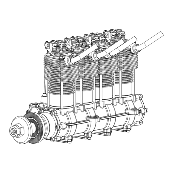
Inline four-cylinder overhead-valve
four-stroke-cycle engine
7-8
9-10
11
ENGINE PARTS LIST
12
CARBURETOR EXPLODED VIEW
13
ENGINE THREE VIEW DRAWINGS
18
1
CONTENTS
19-22
23
24-26
27
28-29
30
31
32
33
34
Advertisement
Table of Contents

Related Manuals for O.S. engine IL-300


Summary of Contents for O.S. engine IL-300
-
Page 1: Table Of Contents
CONTENTS SAFETY INSTRUCTIONS AND 19-22 WARNINGS ABOUT YOUR O.S. ENGINE STARTING NOTES WHEN APPLYING AN RUNNING-IN ("Breaking-in") ELECTRIC STARTER THROTTLE VALVE ADJUSTMENT 24-26 ABOUT THE ENGINE FLIGHT &... -
Page 2: Safety Instructions And Warnings About Your O.s. Engine
(see 'NOTES' all times. section relating to propeller safety). If at some future date, your O.S. engine is acquired by another person, we would respectfully request that these Model engine fuel is poisonous. Do not allow it to instructions are also passed on to its new owner. -
Page 3: Notes When Applying An Electric Starter
NOTES Take care that the glow plug clip or battery leads do not come into contact with the propeller. Also check the linkage to the throttle arm. A disconnected linkage could also foul the propeller. After starting the engine, carry out any needle-valve readjustments from a safe position behind the rotating propeller. -
Page 4: About The Engine
ABOUT THE ENGINE The O.S. IL-300 (Dia-Star) is a four-cylinder inline Booster Cable Set overhead-valve four-stroke-cycle engine of 50cc Leads for glow plug with clip (4pcs.) displacement. The engine maintains the same Lead for earth (ground) (1pc.) features of stress free starting, super smooth idling and high torque power which is always the hallmark of O.S. -
Page 5: Installation
Cylinder Head 3 Cylinder Head 4 Cylinder Head 2 Cylinder Head 1 Exhaust Pipe Cylinder Jacket Front Housing Propeller Washer Lock Nut Crankcase Under Cover Drive Hub Propeller Nut INSTALLATION Needle-valve extension It is essential that the firewall is strong and rigid (e.g. at least 15mm thick) and firmly integrated with the structure of The needle-valve with this engine is designed to incorporate the aircraft. -
Page 6: Fuel Tank & Lines
Exhaust pipe adjustment Carburetor cleanliness It is recommended that the fuel is passed through a filter The direction of the exhaust pipes may be altered in when the tank is filled and that a good in-line filter is accordance with individual installation requirements. The installed between the fuel tank and carburetor. -
Page 7: Glowplug
GLOWPLUG Since the compatibility of the glowplug and Glowplug life fuel may have a marked effect on Particularly in the case of very high performance engines, performance and reliability, it is suggested glowplugs must be regarded as expendable items. However, to use the O.S. -
Page 8: Propeller
PROPELLER The choice of propeller depends on the design and weight of PROPELLER & SPINNER ATTACHMENT the aircraft and on the type of flying in which you will be There is a risk, particularly with powerful four-stroke engines, engaged. Determine the best size and type after practical of the propeller flying off if the prop nut loosens due to experimentation. -
Page 9: Glowplug Heating
GLOWPLUG HEATING Glowplug battery Install Ni-Cd battery in the fuselage, and switch on or off by means of transmitter. (On-board battery) It is necessary to use a glowplug battery of fairly large capacity (10Ah or more) as this is required to heat four glowplugs simultaneously. -
Page 10: Fuel And Lubrication
Lubrication Rear Housing Breather Nipple All parts of the IL-300 are automatically lubricated by the oil Breather Nipple content of the fuel mixture. It is suggested, however, to apply small amount of machine oil or grease to moving parts of the rocker arms before starting the engine. - Page 11 Set the throttle valve approximately 1/4 open from the fully Starting with an electric starter. closed position. Make sure that the direction of rotation of the starter is correct. Connect the glowplug battery. Apply the electric starter. Connect the battery to the glowplug. Fully closed Fully open Set at this position...
-
Page 12: Running-In ("Breaking-In")
Now disconnect the glowplug battery. How to stop the engine Pull down the throttle lever and trim lever on the transmitter Adjust the needle-valve fully. Abrupt adjustment of the needle-valve may cause the Note: engine to stop, especially when it is new and insufficiently Make sure that the throttle linkage is made so that the run-in. -
Page 13: Throttle Valve Adjustment
Needle-valve adjustment Mixture control valve adjustment Adjust the needle-valve following the instructions given in The carburetor of your IL-300 has been factory set for the STARTING section. approximate best result with the fuel tank located in the normal position (i.e. close to the back of the engine and where the... -
Page 14: Flight & Maintenance
Adjusting the mixture control valve In the case of the idle speed being too low, re-set the idle If the engine hesitates, puffing Mixture Control Valve position a little higher by means of the throttle trim on the out a good deal of smoke, before transmitter. -
Page 15: Valve Clearance Adjustment
VALVE CLEARANCE ADJUSTMENT ALL O.S. four-stroke engines have their valve (tappet) The standard valve clearance, on both inlet and exhaust clearances correctly set before they leave the factory. valves, is between 0.04mm and 0.1mm(0.0015-0.004 inch), However, if, after many hours of running time have been measured between valve stem and rocker arm. -
Page 16: Engine Exploded View
ENGINE EXPLODED VIEW C.M2.6x7 C.M3.5x10 C.M3.5x10 C.M3x10 S.M3x3 19-1 C.M2.6x7 C.M3x14 C.M3x8 C.M3x8 48-1 C.M2.6x7 17-1 17-2 10-2 10-1 39 40 C.M3.5x10 32-1 C.M2.6x7 CAP SCREW SETS (10pcs./sets) C.M2.6x7 Code No. Size Pcs. used in an engine 79871020 M2.6x7 Front Housing (4pcs.) Under Cover (8pcs.) C.M3.5x10 Intake Manifold A (2pcs.) Gear Cover (2pcs.) 26-1... -
Page 17: O.s. Genuine Parts & Accessories
EXPLODED VIEW & PARTS LIST Code No. Description 27681900 Needle-valve Assembly 27681970 Needle Assembly S.M3X3 24981837 "O" Ring (2pcs.) 26381501 Set Screw 27381940 Needle-valve Holder Assembly 26711305 Ratchet Spring 22781420 Throttle Lever Retaining Screw 22781411 Throttle Lever 46581200 Carburetor Rotor 26781309 Mixture Control Valve Assembly 24881824... -
Page 18: Three View Drawing
THREE VIEW DRAWING Specifications 12.5 cc x 4 / 0.765 cu.in. x 4 Displacement 25.8 mm / 1.02 in. Bore 24.0 mm / 0.94 in. Stroke 1,800-8,000r.p.m. PracticalR.P.M. Output 2,350 g / 82 oz. Weight Dimensions (mm) 121.3 234.3 6-15 3-Chome Imagawa Higashisumiyoshi-ku Osaka 546-0003, Japan TEL.
Need help?
Do you have a question about the IL-300 and is the answer not in the manual?
Questions and answers