
Subscribe to Our Youtube Channel
Related Manuals for CTS swh-2109

Summary of Contents for CTS swh-2109
-
Page 1: Network Management
SWH-2109 7 x 10/100Base-TX to 2 x 100Base-FX Managed Converter Switch Network Management User's Guide Ver : 1.4... -
Page 2: Copyright Statement
Trademarks CTS is a registered trademark of Connection Technology Systems Inc. Contents subject to revise without prior notice. All other trademarks remain the property of their owners. Copyright Statement Copyright © Connection Technology Systems Inc. This publication may not be reproduced as a whole or in part, in any way whatsoever unless prior consent has been obtained from Connection Technology Systems Inc. -
Page 3: Table Of Contents
Table of Content 1. INTRODUCTION ....................... 4 1.1 Management Options ....................4 1.2 Management Software & Interfaces ................5 1.3 Management Preparations ................... 6 2. CONSOLE PROGRAM ..................... 8 2.1 Local Console Management..................8 2.2 Remote Console Management - Telnet ................ 9 2.3 Console Program Overview .................. -
Page 4: Introduction
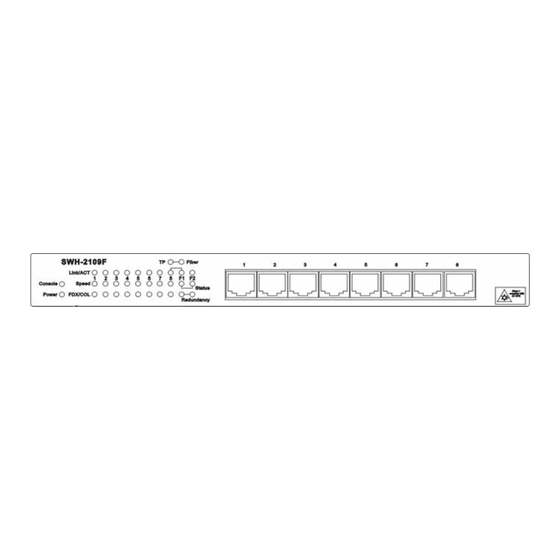
1. INTRODUCTION Thank you for using the 7x10/100TX plus 2x100FX managed converter switch. The built-in management module allows user to configure this managed converter switch and monitor the operation status locally or thru network remotely. 1.1 Management Options Fig. 1 Front Panel RS-232 Duplex SC Connector... -
Page 5: Management Software & Interfaces
1.2 Management Software & Interfaces Following list the choices of management software and interfaces: • Converter switch Console Program • SNMP-based management software Console Program The converter switch has a built-in, menu-driven interface called the Console Program that you can use to: •... -
Page 6: Management Preparations
1.3 Management Preparations After you have decided how to manage your converter switch, you need to make the cable connection, determine the converter switch IP address and, in some cases, install MIB shipped with your converter switch. Connecting the converter switch It is extremely important that cables have the correct pin arrangement and that the proper cables be used when connecting converter switch to another switches, hubs, workstations, etc. - Page 7 addresses allocated to you, consult the allocation organization from which your IP addresses were obtained. Remember that no two devices on a network can have the same address. If you connect to the outside, you must change all the arbitrary IP addresses to comply with those you have been allocated by the allocation organization.
-
Page 8: Console Program
2. CONSOLE PROGRAM This chapter describes how to use your converter switch Console Program, specifically in: • Local Console Management (out-of-band) • Telnet Management (in-band) • Configuring the system • Resetting the system The interface and options are the same with Local Console and Telnet Management. The difference is the type of connection and the port that is used to manage the converter switch. -
Page 9: Remote Console Management - Telnet
2.2 Remote Console Management - Telnet You can manage the converter switch via Telnet session. However, you must first assign a unique IP address to the converter switch before doing so. Use the Local Console to log into the converter switch and set up the IP address for the first time. Follow these steps to manage the converter switch through Telnet session: 1. -
Page 10: Console Program Overview
2.3 Console Program Overview Once you gain the access, a Login Console appear as following, Enter the user name and password then press ENTER to login to the Console Program main menu, Press Tab or or Number directly to select. 1. - Page 11 3. Network Management: Set up or view the IP address and related information of the converter switch required for network management application. Switch Management: Setup switch/port configuration, VLAN configuration and other functions. 5. Switch Monitor: View the operation status and traffic statistics of the ports. 6.
-
Page 12: Navigating The Console Program Screens
2.4 Navigating the Console Program Screens To do this… Use this key… Highlight an option in menu. Tab and or press number directly Select a highlighted option. Enter Pull Down Menu in a choice field. Spacebar Select within Pull Down Menu in a choice field. Toggle between available options in a choice field. - Page 13 1. Timer: X day XX:XX:XX Timer is view-only, shows how long the switch has been up since it was turned on or reset. 2. Pull Down Menu: [ XXXX |] Pull down menu is used if there are more than 2 selections, for example: Port Number Press Spacebar will display the pull down menu as below.
- Page 14 7. Cancel Press Cancel to skip the change and quit the current menu. 8. Help Press Help to view On-Line help as below, This pop up message alerts user that the configuration change will take effect after reset. However, before perform System Reset, user must save the configuration change first.
-
Page 15: System Information
2.5 System Information Select System Information in the Console Program Main menu, following screen appears. Company Name: Enter a company name for this converter switch, up to 55 alphanumeric characters. System Object ID: View only field, predefined System OID. System Contact: Enter contact information for this converter switch, up to 55 alphanumeric characters. - Page 16 RAM size <KB>: View only field shows the product RAM size. Fiber Port: View only field shows the fiber port number and fiber port perimeters. - 1310 fiber transceiver operation wavelength (nm) - SC fiber transceiver connector type - 2KM fiber transceiver operation length TP Port: View only field shows the total TP port number.
-
Page 17: User Authentication
2.6 User Authentication To prevent any un-authorized operation, only registered users are allowed to operate the converter switch. Any user wants to operate the converter switch need to register into the user list first. To view or change current registered users, select 2. User Authentication from the main menu, following screen appears. - Page 18 Current/Total/Max Users: View only field. Specify: Current: Current registered user number. Total: Total registered user number. Max Users: Maximum available registered user number, default 10. Account State: Press Spacebar to Enable or Disable this User Account. User Name: Specified the authorized user login name, up to 20 alphanumeric characters. Password: Enter desired user password, up to 20 alphanumeric characters.
- Page 19 Full access right but cannot modify user account & system information, Read & Write cannot load factory setting Allow to view only. Read Only Complete forbid to access. Access Denied NOTICE: To prevent un-caution operation, a user cannot Delete, Modify User Name or Enable/Disable account states.
-
Page 20: Network Management
2.7 Network Management In order to enable network management of the converter switch, proper network configuration is required. To do this, select option Network Management from the Console main menu, following screen appears. 1. Network Configuration: Setup the required IP configuration of the converter switch. 2. -
Page 21: Network Configuration
2.7.1 Network Configuration Select option Network Configuration from the Network Management menu, following screen appears. MAC Address: This view-only field shows the unique and permanent MAC address assigned to the converter switch. You cannot change the converter switch MAC address. Configuration Type: Press Spacebar to select using "DHCP"... -
Page 22: System Service Management
The default value of this parameter is 0.0.0.0, which means no gateway exists and the network management station and converter switch are on the same network. Current State: This view only field shows currently assigned (by DHCP or manual) IP address, Subnet Mask &... -
Page 23: Rs232/Telnet/Console Configuration
2.7.3 RS232/Telnet/Console Configuration Select option RS232/Telnet/Console Configuration from the Network Management menu, following screen appears. Baud Rate: 9600 bps, RS-232 setting, view only field. Stop Bits: 1, RS-232 setting, view only field. Parity Check: None, RS-232 setting, view only field. Word Length: 8, RS-232 setting, view only field. -
Page 24: Device Community
2.7.4 Device Community Select option Device Community from the Network Management menu, following screen appears. Up to 10 Device Community maybe set. Use Delete to remove a registered community. Press New to add a new community. Press Edit to view the current community setting. Following screen appears, Current/Total/Max Agents: View only field. - Page 25 Current: Current registered community number. Total: Total registered community user number. Max Users: Maximum available registered community number, default 10. Account State: Press Spacebar to Enable or Disable this Community Account. Community: Specified the authorized SNMP community name, up to 20 alphanumeric characters.
-
Page 26: Trap Destination
2.7.5 Trap Destination Select option Trap destination from the Network Management menu, following screen appears. State: Enable or Disable to send Trap to the specified destination. Destination: Enter the specified IP address of the network management system that will receive the trap. Community: Enter the community name of the network management system. -
Page 27: Trap Configuration
2.7.6 Trap Configuration Select option Trap Configuration from the Network Management menu, following screen appears. Cold Start Trap: Enable or Disable the converter switch to send Cold Start trap after power Warm Start Trap: Enable or Disable the converter switch to send Warm Start trap after system reset. -
Page 28: Switch Management
2.8 Switch Management In order to manage the converter switch and setup required switching function, select option Switch Management from the Console main menu, following screen appears. 1. Switch Configuration: Setup acceptable frame size and address learning, etc. 2. Priority and Rate Limit Configuration: Enable/Disable Port priority and setup Port Rate limit, etc. -
Page 29: Switch Configuration
2.8.1 Switch Configuration Select option Switch Configuration from the Switch Management menu, following screen appears. Maximum Frame Size: Press Spacebar to toggle 1522 and 1536 two ranges. Address Learning: Enable is default to learn MAC addresses in RAM, otherwise disable option would stop learn MAC address. -
Page 30: Priority And Rate Limit Configuration
2.8.2 Priority and Rate limit Configuration Select option Priority and Rate limit Configuration from the Switch Management menu, following screen appears. Priority Mode: Use spacebar to select Default, IP, TAG, IP+Tag, Tag+IP modes. Default mode: default value which Schedule mode is Weight (8:4:2:1) and port priority set Q1, where Weight (8:4:2:1) mean Q4:Q3:Q2:Q1 4 kinds of frames type quantity occupied bandwidth ratio is 8:4:2:1 when frames passing over switch based on IP TOS Priority MAP and Tag Priority Map. - Page 31 Tag Priority Map: Use spacebar to select 0,1,2,3 tag values as priority level. The second field is up to first field use which TAG with what kind of queue. Ingress Rate Limit Mode: There are two options, first field is All Frames and Broadcast.It could be toggle by space bar, All Frames mean limit all of frames pass.
-
Page 32: Port Configuration
2.8.3 Port Configuration Port Number: Using spacebar to select All, port 1, port 2, and port 3. Port State: Enable or disable current port state. Port Type: Press Spacebar to choice Auto-Negotiation, manual,10M bps and Half Flow Control: Press spacebar to select Enabled/Disabled. -
Page 33: Vlan Configuration
2.8.4 VLAN Configuration A Virtual Local Area Network (VLAN) is a network topology configured according to a logical scheme rather than the physical layout. VLAN can be used to combine any collection of LAN segments into a group that appears as a single LAN. VLAN also logically segment the network into different broadcast domains. -
Page 34: Port Based Vlan Configuration
2.8.4.1 Port Based VLAN Configuration Port-based VLAN can effectively segment one network into several Broadcast Domains, Broadcast/Multicast and unknown packets will be limited to within the VLAN. Port Based VLAN is uncomplicated and fairly rigid in implementation, it is best used for network administrators who wish to quickly and easily setup VLAN in order to isolate the effect of broadcast packets on their network Press New to add a new VLAN entity. - Page 35 VLAN Name: Use default name or specify a VLAN name. VLAN Members: Moving cursor to VLAN member mark with V to denote which port belong to VLAN.
-
Page 36: 802.1Q Vlan Concept
2.8.4.2 802.1Q VLAN Concept Port Based VLAN is simple to implement and use, but it cannot deploy cross switches VLAN. The 802.1Q protocol was developed in order to provide the solution. By tagging VLAN membership information to Ethernet frames, the IEEE 802.1Q can help a network administrator to break up large switched networks into smaller segments so that broadcast and multicast traffic won't grab too much of the available bandwidth, as well as providing a higher level of security between segments of internal networks. - Page 37 Ingress The point at which a frame is received on a switch and the switching decisions must be made. The switch examines the VID (if present) in the received frames header and decides whether and where to forward the frame. If the received frame is untagged, the switch will tag the frame with the PVID for the port on which it was received.
- Page 38 1. If an egress port is connected to an 802.1Q-compliant switch or end system, tagging should be Enable so the other device can utilize the VLAN and priority tags. 2. If an egress port is connected to a non-compliant switch or end-station, the tags should be stripped off and the frame transmitted untagged so that the receiving device can read the normal Ethernet frame.
-
Page 39: 802.1Q Vlan Configuration
2.8.4.3 802.1Q VLAN configuration Press New to add a new VLAN entity. Press Edit to view the current VLAN setting. Use Delete to remove a VLAN entity. Following screen appears, if you choice IEEE 802.1Q Tag VALN mode. - Page 40 VLAN ID: From 1 to 4094, specify a VLAN ID VLAN Name: Use default name or specify a VLAN name. VLAN Members: Moving cursor to VLAN member mark with V to denote which port belong to VLAN. And, the following screen appears, if you choice IEEE 802.1Q Tag VLAN mode...
-
Page 41: Configuration Default Port Vlan Id
2.8.4.4 Configuration Default Port VLAN ID There are 4 modes to select for 802.1q Tag VLAN Mode: It ignores all setting below and Tagged packet. This setting depends on Port Disabled: Based VLAN. If receive a packet without Tag, the packet follows up the setting of Tagging. If Fallback: receive a Tagged packet, the packet follows up the previous setting of VLAN table. - Page 42 Default Port VLAN ID (PVID): 1 ~ 4094 setting Default Egress Mode: F: When VLAN table dose not exist or VLAN mode is disabled, the Egress packet will be unmodified forwarded. U: When VLAN table dose not exist or VLAN mode is disabled, the Egress packet will be untagged.
-
Page 43: Switch Monitor
2.9 Switch Monitor Switch monitor allow user to monitor the real time operation status of the converter switch. User may monitor the port link up status or traffic counters for maintenance or diagnostic purpose. Select option Switch Monitor from the Console main menu, following screen appears. -
Page 44: Switch Port State
2.9.1 Switch Port State In order to view the real time port status of the switch, select Switch Port State from the Switch Monitor menu, following screen appears, Port Number: The number of the port. Media Type: The media type of the port; could be TP or Fiber. Link State: The current link status of the port, could be Up or Down. -
Page 45: Port Traffic Statistics
2.9.2 Port Traffic Statistics In order to view the real time port traffic statistics status of the switch, select Port Traffic Statistics from the Switch Monitor menu, following screen appears Bytes Received: Total bytes received from current port. Frames Received: Total frames received from current port. Utilization: real port traffic ratio to current port total bandwidth. -
Page 46: Port Packet Error Statistics
2.9.3 Port Packet Error Statistics Port Packet Error Statistics Mode Counters allow viewing the port error history of the converter switch, Event Mode counters are calculated since the last time that counter was reset or cleared. Select Port packet Error Statistics from the Switch Monitor menu, following screen appears, Use <- &... - Page 47 RX Undersized Frames: Total frames received shorter than 64 bytes. Total frames received longer than maximum frame size. RX Oversized Frames: Total frames received had both Oversize & CRC error. RX Jabbers: Total received frames dropped due to resources shortage. RX Dropped frames: Total frames not transmitted due to resources shortage.
-
Page 48: Port Analysis Statistics
2.9.4 Port Analysis Statistics Port Analysis Statistics Mode Counters allow viewing the port analysis history of the converter switch, Event Mode counters are calculated since the last time that counter was reset or cleared. Select Port analysis Statistics from the Switch Monitor menu, following screen appears, Total 64 bytes packets received. -
Page 49: Mac Address Table
2.9.5 MAC address table MAC address table display MAC addresses learned since reset system and MAC address learning enable. Above table mean MAC addresses learn from each port of the switch. Press “U” to Update Table Press “C” to Clear Table... -
Page 50: System Utility
2.10 System Utility System Utility allow user easy to operate and maintain the system. Select option System Utility from the Console main menu, following screen appears. 1. Ping: Ping allow user to ping a specified network device. 2. Update Firmware: Allow user to update the latest firmware, save current configuration, or restore previous configuration to the converter switch. - Page 51 4. Load Factory Setting Except Network Configuration: Select this will also return the configuration of the converter switch to the factory default settings. However, this will not return the IP and Gateway addresses to the factory default.
-
Page 52: Ping
2.10.1 Ping Ping refer to ICMP Echo Request, a device receive the Ping request will respond with an ICMP Echo Reply. The converter switch built in Ping function allow network administrator easily identify the network connection. Select Ping from the System Utility menu, following screen appears, IP Address: Enter the desired IP address that the converter switch will Ping. -
Page 53: Event Log
2.10.2 Event Log Event log keep tract of user login, logout timestamp, Select Event Log from the System Utility menu, following screen appears... -
Page 54: Update Firmware
2.10.3 Update Firmware The converter switch has built-in both TFTP and FTP clients. User may save or restore their configuration and update their Firmware on line. Select Update Firmware from the System Utility menu, following screen appears, Protocol: Press Space Bar to select preferred protocol - FTP or TFTP. File Type: Press Space Bar to select the file to process - Firmware or Configuration. -
Page 55: Load Factory Setting
2.10.4 Load Factory Setting Load Factory Setting will return all the configuration of the converter switch to the factory default settings include the IP and Gateway address. Load Factory Setting is useful when network administrator like to re-configure the system. A system reset is required to put all changes effect after Load Factory Setting. -
Page 56: Load Factory Setting Except Network Configuration
2.10.5 Load Factory Setting Except Network Configuration Load Factory Setting Except Network Configuration will return all the configuration of the converter switch to the factory default settings. However, IP and Gateway addresses will not return to the factory default. Load Factory Setting Except Network Configuration is extremely useful when a network administrator need to re-configure the system "REMOTELY". -
Page 57: Save Configuration
2.11 Save Configuration In order to save configuration setting permanently, user need to save configuration first before reset the converter switch. Select Save Configuration from the Console main menu, following screen appears. To save the Configuration, select OK then press Enter. -
Page 58: Reset System
2.12 Reset System After configuration change, reset system to take change effect. Select Reset System from the Console main menu, following screen appears. To perform System Reset, Select OK then press Enter. -
Page 59: Logout
2.13 Logout Console Logout will stop current RS-232 or Telnet connection between the system and the To perform Logout, select option Logout from the Console main menu, following screen appears. To logout, select OK then press ENTER. -
Page 60: Snmp Network Management
3. SNMP NETWORK MANAGEMENT The Simple Network Management Protocol (SNMP) is an application-layer protocol that facilitates the exchange of management information between network devices. It is part of the TCP/IP protocol suite. SNMP enables network administrators to manage network performance, find and solve network problems, and plan for network growth. SNMP consists following key components, Managed device is a network node that contains SNMP agent.
Need help?
Do you have a question about the swh-2109 and is the answer not in the manual?
Questions and answers