
Subscribe to Our Youtube Channel
Related Manuals for Behringer Autocom Pro MDX1400


Summary of Contents for Behringer Autocom Pro MDX1400
- Page 1 User’s Manual Version 1.4 June 2001 www.behringer.com Downloaded from www.Manualslib.com manuals search engine...
-
Page 2: Safety Instructions
AUTOCOM PRO MDX1400 SAFETY INSTRUCTIONS CAUTION: To reduce the risk of electric shock, do not remove the cover (or back). No user serviceable parts inside; refer servicing to qualified personnel. WARNING: To reduce the risk of fire or electric shock, do not expose this appliance to rain or moisture. - Page 3 It is our philosophy to share our joy with you, because you are the most important member of the BEHRINGER family. With your highly competent suggestions for new products you’ve greatly contributed to shaping our company and making it successful.
- Page 4 Switchable sidechain input with sidechain monitor function s Operating level switchable from +4 dBu to -10 dBV s Servo-balanced gold-plated XLR and 1/4" TRS connectors s High-grade output transformer BEHRINGER OT-1 can be retrofitted s Manufactured under ISO9000 certified management system Downloaded from www.Manualslib.com...
-
Page 5: Table Of Contents
AUTOCOM PRO MDX1400 TABLE OF CONTENT 1. INTRODUCTION........................6 1.1 The Design Concept ........................6 1.2 Before you begin ..........................7 2. CONTROLS ..........................8 2.1 Expander/Gate Section ........................8 2.2 Compressor Section ........................9 2.3 Dynamic Enhancer Section ......................10 2.4 Rear Panel Control Elements Of The AUTOCOM PRO .............. -
Page 6: Introduction
Additionally, we have succeeded in refining the audio properties as well as the circuit topology. For the first time, the AUTOCOM PRO MDX1400 uses SMD technology (Surface Mounted Device). These sub-miniature components known from aerospace technology allow for an extreme packing density, plus improve the unit’s reliability. -
Page 7: Before You Begin
If the unit is damaged, please do not return it to BEHRINGER, but notify your dealer and the shipping company immediately, otherwise claims for damage or replacement may not be granted. -
Page 8: Controls
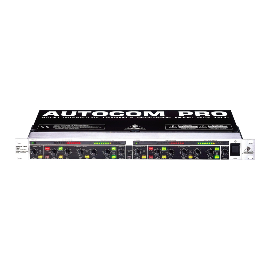
2. CONTROLS Fig. 2.1: AUTOCOM PRO front panel The BEHRINGER AUTOCOM PRO has two identical channels. Each channel is equipped with 8 backlit push-buttons, 7 rotary controls and 26 LED’s. The COUPLE switch is for stereo operation: By engaging the COUPLE switch the AUTOCOM PRO is converted to stereo mode, where the controls of the left channel take over the control of both audio channels. -
Page 9: Compressor Section
AUTOCOM PRO MDX1400 2.2 Compressor Section Fig. 2.3: Control elements of the compressor section The THRESHOLD control sets the threshold point for the compressor section. It has a range of -40 to +20 dB. If the channel is switched to INTERACTIVE mode (Interactive Knee Adaptation), a “Soft Knee”... -
Page 10: Dynamic Enhancer Section
Or use our online registration option available on the Internet at www.behringer.com. FUSE HOLDER / VOLTAGE SELECTOR. Please make sure that your local voltage matches the voltage indicated on the unit, before you attempt to connect and operate the AUTOCOM PRO. -
Page 11: Applications
3. APPLICATIONS In this section, several typical applications of the BEHRINGER AUTOCOM PRO are discussed. The following basic settings can resolve most dynamic problems. They are the ideal starting point. Please take the time to study the application examples carefully, in order to be able to make full use of the AUTOCOM PROs capabilities in the future. -
Page 12: Expander/Gate Section
Noise gates however, can be seen as “high ratio” expanders. If the signal falls below the threshold, it is radically attenuated. The BEHRINGER AUTOCOM PRO is equipped with a newly developed IRC (Interactive Ratio Control) Expander, the ratio of which is automatically adjusted dependent on the program material. The response characteristics of conventional expanders tend to cut into the signal abruptly and the result of this is unacceptable most of the time. -
Page 13: Initial Settings For The Expander/Gate Section
Patch the BEHRINGER AUTOCOM PRO into a snare drum channel for example and adjust it so that triggering only occurs on snare hits. Each mic should be set to its maximum operating level, monitored (see SC MON switch) and the THRESHOLD level set so that each snare hit sounds acoustically clean and seperate, as though it was played on its own. -
Page 14: Reducing Feedback In Stage Mics
It will prove useful to use the BEHRINGER AUTOCOM PRO as the last component in the chain of effects units and use the noise reduction function of the Expander/Gate section. We recommend that you use a slow release time in order to maintain the natural reverb. -
Page 15: Initial Settings For The Compressor Section
AUTOCOM PRO MDX1400 Output Gain 0 dB Threshold Ratio 2:1 Hard Knee Ratio 4:1 Limiter oo:1 IKA Curve Input Fig. 3.2: IKA characteristic of the compressor section The new IKA (Interactive Knee Adaptation) circuit prevents aggressive compression, created by high ratios, from sounding too unnatural. -
Page 16: The Autocom Pro As A Sound Effects Unit
The AUTOCOM PRO MDX1400 offers a solution to this problem that is by much more elegant. The SC Filter switch allows you to activate a highpass filter in the control signal path of the compressor. This filter makes sure that midrange and treble range frequencies are taken into account to a greater extent, and that a low-frequency signal triggers less compression than a midrange/treble signal of comparable level. -
Page 17: Initial Settings For The Dynamic Enhancer Section
AUTOCOM PRO MDX1400 Output 0 dB No Gain Reduction With Enhancer -20 dB 20 dB Gain Reduction Without Enhancer Frequency Fig. 3.3: The frequency response with and without dynamic enhancer 3.4.1 Initial Settings For The Dynamic Enhancer Section Turn the PROCESS control beginning from “Off” to a value, where you have the impression of a correct frequency response at compression. -
Page 18: The Autocom Pro In Digital Recording And Sampling
It is recommended that you use the Behringer AUTOCOM PRO in order to protect the speaker. “Brick Wall” peak limiters are not normally necessary for PA systems, as amplifiers and loudspeakers are tolerant of short signal peaks. -
Page 19: Protection Of A System With An Active Crossover
4.2.2 Protection Of A System With An Active Crossover For systems using active crossovers, there are two ways to use the BEHRINGER AUTOCOM PRO. The unit may be inserted between the console output and the crossover input. In this application, the BEHRINGER AUTOCOM PRO will process the entire audio frequency spectrum. -
Page 20: External Sidechain Applications
When de-essing, simply insert an equalizer not into the audio path but into the sidechain path of the BEHRINGER AUTOCOM PRO. The equalizer is inserted between the SC SEND output and the SC RETURN input of the BEHRINGER AUTOCOM PRO. -
Page 21: Frequency Selective Filtering Of Unwanted Signals
5.2.4 Emphasizing Musical Instruments During Recording On the other hand, you can use the BEHRINGER AUTOCOM PRO to bring out an instrument solo or a lead vocal in a cluttered mix. Using the SC MON switch, match the frequencies of the equalizer to the frequencies of the instruments to be emphasized and for this it is best to use a notch filter with a high slope. -
Page 22: X93;Voice-Over” Compression (“Ducking”)
Compressor and Dynamic Enhancer sections are switched off. The bass guitar track is connected to the audio chain of the BEHRINGER AUTOCOM PRO, while the bass drum is connected to the SC RETURN input. By activating the SC EXT switch, the bass guitar is now triggered by the bass drum. -
Page 23: Compressors/Limiters
The need therefore arises for a fast acting automatic gain control system which will constantly monitor the signals and which will always adjust the gain to maximize the signal-to-noise ratio without incurring signal distortion. This device is called a compressor or limiter. This system is a part of the BEHRINGER AUTOCOM PRO. Compressors/Limiters By measuring the dynamic range of musical instruments in live recording situations, you will find that extreme amplitudes occur which often lead to overload in subsequent signal processing equipment. -
Page 24: Expanders/Noise Gates
7.1 Inputs And Outputs 7.1.1 Balanced Inputs And Outputs As standard, the BEHRINGER AUTOCOM PRO is installed with electronically servo-balanced inputs and outputs. The new circuit design features automatic hum and noise reduction for balanced signals and thus allows for trouble-free operation, even at high operating levels. Externally induced mains hum etc. will be effectively suppressed. -
Page 25: Audio Connections
The BEHRINGER transformer OT-1 is designed to the highest exacting standards and is available as an accessory. The audio inputs and outputs on the BEHRINGER AUTOCOM PRO are fully balanced. If possible, connect the unit to other devices in a balanced configuration to allow for maximum interference immunity. -
Page 26: Technical Data
AUTOCOM PRO MDX1400 8. TECHNICAL DATA AUDIO INPUT Connectors XLR and 1/4" jack Type RF filtered, servo-balanced input Impedance 50 kOhm balanced, 25 kOhm unbalanced Nominal Operating Level +4 dBu/-10 dBV switchable Max. Input Level +21 dBu balanced and unbalanced CMRR typ. -
Page 27: Technical Data
3.4 kg BEHRINGER is constantly striving to maintain the highest professional standards. As a result of these efforts, modifications may be made from time to time to existing products without prior notice. Specifications and appearance may differ from those listed or illustrated. -
Page 28: Warranty
(user included) will void the warranty. at its sole discretion, either repair or replace the product. 6. If an inspection of the product by BEHRINGER shows that the 2. If the warranty claim proves to be justified, the product will be defect in question is not covered by the warranty, the inspection returned to the user freight prepaid.
Need help?
Do you have a question about the Autocom Pro MDX1400 and is the answer not in the manual?
Questions and answers