Table of Contents
Advertisement
Quick Links
Advertisement
Table of Contents

Subscribe to Our Youtube Channel
Related Manuals for SOYO 5ehm


Summary of Contents for SOYO 5ehm
- Page 1 Ê 5EH5/5EHM 586 CPU Supported PCI Mainboard User’s Guide & Technical Reference...
-
Page 2: About This Guide
It is the policy of Soyo Computer Inc. to respect the valid patent rights of third parties and not to infringe upon or assist others to infringe upon such rights. -
Page 3: Table Of Contents
Table of Contents Chapter 1: Introduction ..........1 Key Features ................1 Unpacking the Mainboard ............2 Electrostatic Discharge Precautions..........2 Mainboard Layout w/ Default Settings ........3 Chapter 2: Hardware Setup ..........5 Jumpers ..................5 JP5: CMOS Clear Jumper ............ 5 JP22: CPU Burst Mode Jumper ........... - Page 4 ATX PWR (P1)Ð ATX Power Supply Connector ....17 JP12 Ð CPU Cooling Fan Connector ........18 IR Ð Infrared Device Connector .......... 18 Chapter 3: BIOS Setup ..........19 Standard CMOS Setup .............. 20 BIOS Features Setup ..............22 Chipset Features Setup..............
-
Page 5: Chapter 1: Introduction
1 Introduction The EQ82C663X PCI mainboard is a high-performance AT form-factor system board that supports P54C/P55C family CPUs. This mainboard is fully compatible with industry standards and adds many technical enhancements. Key Features ¥ CPU Ñ Supports P54C/P55C family CPUs running at 90~233 MHz speeds;... -
Page 6: Unpacking The Mainboard
Introduction Unpacking the Mainboard The mainboard package contains: ¥ The EQ82C663X Mainboard ¥ One CD (including UserÕs Manual, Drivers, and Utilities) Note: Do not unpack the mainboard until you are ready to install it. Follow the precautions below while unpacking the mainboard. 1. -
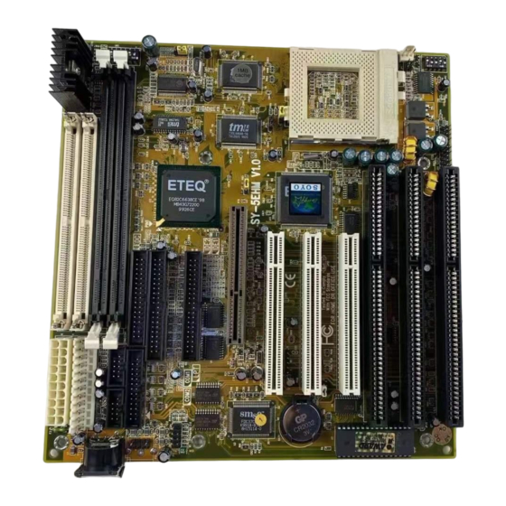
Page 7: Mainboard Layout W/ Default Settings
Introduction Mainboard Layout w/ Default Settings 16 15 Figure 1Ð1. Mainboard Layout 1. ZIF socket 7 12. IDE1/IDE2 Connectors 2. EQ82C663X Chipset 13. Parallel Port Connector 3. Pipelined Burst SRAM 14. COM1/COM2 Connector 4. Super I/O 15. ATX Power Connector 5. - Page 8 JP37 (for 586 CPUs) P.B. SRAM JP30 64Kx64 * If the board is 1 2 3 5EHM (1M Cache) then it should have JP12 two P.B. SRAM. JP10 Figure 1Ð2. Regular Mainboard Default Setting Note: Make sure the system is well ventilated to prevent overheating...
-
Page 9: Chapter 2: Hardware Setup
2 Hardware Setup This chapter explains how to configure the mainboardÕs hardware. After you install the mainboard, you can set jumpers, install memory on the mainboard, and make case connections. Refer to this chapter whenever you upgrade or reconfigure your system. CAUTION: Turn off power to the mainboard, system chassis, and peripheral devices before performing any work on the... -
Page 10: Jp22: Cpu Burst Mode Jumper
Hardware Setup JP22: CPU Burst Mode Jumper Due to different designs, there are two kinds of CPU burst modes: Interleave Burst and Linear Burst. Select the correct mode according to the CPU you are using. CPU Burst Mode JP22 Interleave (for P54C/P55C and AMD K5/K6 CPU) Linear... -
Page 11: Jp2, Jp6: Power Supply Selection Jumpers
Hardware Setup JP2, JP6: Power Supply Selection Jumpers These two jumpers let you select either the AT or the ATX power supply. Use only one power supply at a time on this mainboard. AT Power Supply (default) ATX Power Supply JP37: DIMM Voltage Jumper There are two kinds of DIMM voltages in the marketÑ3.3V and 5VÑ... -
Page 12: Jp9, Jp10: Sdram Frequency Selection Jumper
Hardware Setup JP9, JP10: SDRAM Frequency Selection Jumper SDRAM frequency is the same as CPU frequency (60/66/75/83/100 MHz) (default) SDRAM frequency is the same as AGP frequency (66 MHz) SDRAM is running at CPU frequency JP10 (default) SDRAM is running at AGP frequency Note: 1. -
Page 13: Cpu Type Configuration
Hardware Setup CPU Type Configuration SW1 and JP30 are the only switchs/jumpers that you need to set for your CPU on this mainboard. Make sure that you know the type of CPU that you are installing and refer to the proper settings which are listed below. If you have a higher frequency CPU then the one listed below, see the ÒQuick Installation GuideÓ... -
Page 14: P54C/P55C Series Cpus Settings (Continued)
Hardware Setup P54C/P55C Series CPUs Settings (Continued) Voltage Setting Frequency Setting (SW1) JP7 JP8 JP9 JP10 (JP30) External• : 60MHz P54CÐ120MHz Ratio• : 2.0x 1 2 3 4 5 6 P54CÐ133MHz External• : 66MHz JP30 (default) Ratio• : 2.0x 1 2 3 4 5 6 External•... -
Page 15: Amd K5/K6 Series Cpus Setting
Hardware Setup AMD K5/K6 Series CPUs Setting Voltage Setting Frequency Setting (SW1) JP7 JP8 JP9 JP10 (JP30) External• : 60MHz AMD K5ÐPR90 Ratio• : 1.5x 1 2 3 4 5 6 JP30 External• : 66MHz AMD K5ÐPR100 Ratio• : 1.5x 1 2 3 4 5 6 2-3 open 2-3 1-2 External•... -
Page 16: Cyrix 6X86/L/Mx Series Cpus Setting
Hardware Setup Cyrix 6x86/L/MX Series CPUs Setting Voltage Setting Frequency Setting (SW1) JP7 JP8 JP9 JP10 (JP30) JP30 JP30 Cyrix 6x86/6x86L External• : 60MHz ÐPR150 Ratio• : 2.0x 1 2 3 4 5 6 2-3 open 2-3 1-2 Cyrix 6x86/6x86L External•... -
Page 17: Memory Configuration
Hardware Setup Memory Configuration The mainboard supports two strips of 72-pin 5V FPM/EDO DRAM (SIMM) from 4 to 32MB and two strips of 168-pin 3.3V/5V Unbuffered DIMM modules from 8 to 128MB. The mainboard requires SIMM modules of at least 70ns access time. You can install memory in any combination without having to rely on a memory configuration table. -
Page 18: Multi I/O Port Addresses
Hardware Setup Multi I/O Port Addresses Default settings for multi-I/O port addresses are shown in the table below. Port I/O Address Status LPT1* 378H ECP + EPP COM1 3F8H COM2 2F8H * If default I/O port addresses conflict with other I/O cards (e.g. sound cards or I/O cards), you must adjust one of the I/O addresses to avoid address conflict. -
Page 19: Hd Led Ð Ide Device Led Connector
Hardware Setup HD LED – IDE Device LED Connector Attach a 2-pin IDE drive LED cable to this connector. The LED lights when an IDE device is active. KB_LOCK – Keylock & Power LED Connector It is a 5-pin connector for a lock that may be installed on the system case for enabling or disabling the keyboard. -
Page 20: Jp44 Ð Wake-On-Lan (Wol) Header
Hardware Setup JP44 – Wake-On-LAN (WOL) Header Attach a 3-pin connector from the LAN card which supports the Wake- On-LAN (WOL) function. This function lets users wake up the connected computer through the LAN card. (The cable should be included with the LAN card.) JP44 Pin Assignment SENSOR PS1 –... -
Page 21: At Pwr (Cn1)Ð At Power Supply Connectors
Hardware Setup AT PWR (CN1)– AT Power Supply Connectors The mainboard requires a power supply with at least 200 watts and a Òpower goodÓ signal. AT PW has two 6-pin male header connectors. Plug the dual connectors from the power directly onto the board connector while making sure the black leads are in the center. -
Page 22: Jp12 Ð Cpu Cooling Fan Connector
Hardware Setup JP12 – CPU Cooling Fan Connector Attach a 3-pin CPU cooling fan cable to this connector. Make sure the pin assignment of the fan matches this connector or you may damage the system. This fan will stop when the system is into the suspend mode, if you enable the Suspend Mode in the BIOS setup. -
Page 23: Chapter 3: Bios Setup
3 BIOS Setup The mainboardÕs BIOS setup program is the ROM PCI/ISA BIOS from Award Software Inc. Enter the Award BIOS programÕs Main Menu as follows: 1. Turn on or reboot the system. After a series of diagnostic checks, you are asked to press DEL to enter Setup. 2. -
Page 24: Standard Cmos Setup
BIOS Setup Standard CMOS Setup Run the Standard CMOS Setup as follows. 1. Choose ÒSTANDARD CMOS SETUPÓ from the Main Menu. A screen appears. ROM PCI/ISA BIOS STANDARD CMOS SETUP AWARD SOFTWARE, INC. Date (mm:dd:yy) : Sat, Jan 10 1998 Time (hh:mm:ss) : 7 : 30 : 33 HARD DISKS... - Page 25 BIOS Setup Primary Large Ð Large IDE hard disk (for certain (Secondary) hard disk) Master & Slave Note: If you have any questions on your hard (Continued) disk type or mode, ask your hard disk provider or previous user for details. Drive A &...
-
Page 26: Bios Features Setup
BIOS Setup BIOS Features Setup Run the BIOS Features Setup as follows. 1. Choose ÒBIOS FEATURES SETUPÓ from the Main Menu and a screen with a list of items appears. (The screen below shows the BIOS default settings.) ROM PCI/ISA BIOS BIOS FEATURES SETUP AWARD SOFTWARE, INC. - Page 27 BIOS Setup Quick Power Enabled provides a fast POST at boot-up . On Self Test Boot Sequence Choose the boot device sequence as your need. For example, ÒA, C, SCSIÓ means BIOS will look for an operating system first from drive A, drive C, then SCSI device.
- Page 28 BIOS Setup Security Option Choose Setup or System. Use this feature to prevent unauthorized system boot-up or use of BIOS Setup. ÒSystemÓ Ð Each time the system is booted the password prompt appears. ÒSetupÓÐ If a password is set, the password prompt only appears if you attempt to enter the Setup program.
-
Page 29: Chipset Features Setup
BIOS Setup Chipset Features Setup The Chipset Features Setup option changes the values of the chipset registers. These registers control system options in the computer. Note: Change these settings only if you are familiar with the Chipset. Run the Chipset Features Setup as follows. 1. - Page 30 BIOS Setup Linear Burst Choose Enabled or Disabled (default). Set this option to Enabled when using Cyrix processor. Video BIOS Cacheable Disabled Ð The video BIOS C0000H- C7FFFH is not cached. Enabled Ð The video BIOS C0000H- C7FFFH is cacheable if cache controller is enabled.
-
Page 31: Power Management Setup
BIOS Setup Power Management Setup The Power Management Setup option sets the systemÕs power saving functions. Run the Power Management Setup as follows. 1. Choose ÒPOWER MANAGEMENT SETUPÓ from the Main Menu and a screen with a list of items appears. ROM PCI/ISA BIOS CMOS SETUP UTILITY POWER MANAGEMENT SETUP... - Page 32 BIOS Setup PM Control by Choose Yes (default) or No. APM stands for Advanced Power Management. To use APM, you must run Òpower.exeÓ under DOS v6.0 or later version. Video Off Option Susp, Stby→off: Video off when the system runs into Suspend or Standby mode.
- Page 33 BIOS Setup Suspend Mode The default is Disabled. Only an SL-Enhanced (or SMI) CPU can enter this mode. Time is adjustable from 1 Min to 1 Hour. Under Suspend mode, the CPU stops completely (no instructions are executed.) Choose Off (default) or On to disable or enable the power management.
-
Page 34: Pnp/Pci Configuration Setup
BIOS Setup IRQ# When set at ÒPrimaryÓ the processor will power down only after the BIOS detects a Òno IRQ activityÓ during the time specified by the Suspend time. If set at ÒSecondary eventÓ the system will distinguish whether an interrupt accesses and I/O address or not. - Page 35 BIOS Setup 2. Use the arrow keys to move between items and select values. Modify selected fields using the PgUp/PgDn/+/Ð keys. A short description of screen items follows: Resources Manual Ð BIOS doesnÕt manage PCI/ISA PnP Controlled By card (i.e., IRQ) automatically. Auto Ð...
-
Page 36: Load Setup Defaults
BIOS Setup Load Setup Defaults This item loads the system values you have previously saved. Choose this item and the following message appears: ÒLoad SETUP Defaults (Y/N)? NÓ To use the SETUP defaults, change the prompt to ÒYÓ and press <Enter>. -
Page 37: Integrated Peripherals
BIOS Setup Integrated Peripherals The Integrated Peripherals option changes the values of the chipset registers. These registers control system options in the computer. Note: Change these settings only if you are familiar with the Chipset. Run the Integrated Peripherals as follows. 1. - Page 38 BIOS Setup IDE Primary Master PIO/ Choose Auto (default) or mode 0~4. IDE Primary Slave PIO/ Mode 0 is the slowest speed, and HDD IDE Secondary Master mode 4 is the fastest speed. For better PIO/ performance and stability, we suggest IDE Secondary Slave PIO you use the Auto setting to set the HDD control timing.
- Page 39 BIOS Setup Onboard Parallel Port Choose the parallel port I/O address: 378H/IRQ7 (default), 3BCH/IRQ7, 278H/IRQ5, or Disabled to disable this port. Parallel Port Mode Choose ECP+EPP (default), SPP, EPP, or ECP. The mode depends on your external device that connects to this port. ECP Mode Use DMA Choose DMA3 (default) or DMA1.
-
Page 40: Supervisor Password
BIOS Setup Supervisor Password Based on the setting you made in the ÒSecurity OptionÓ of the ÒBIOS FEATURES SETUPÓ, this Main Menu item lets you configure the system so that a password is required every time the system boots or an attempt is made to enter the Setup program. -
Page 41: User Password
BIOS Setup User Password Based on the setting you made in the ÒSecurity OptionÓ of the ÒBIOS FEATURES SETUPÓ, this Main Menu item lets you configure the system so that a password is required every time the system boots or an attempt is made to enter the Setup program. -
Page 42: Ide Hdd Auto Detection
BIOS Setup IDE HDD Auto Detection This Main Menu item automatically detects the hard disk type and configures the STANDARD CMOS SETUP accordingly. This function is only valid for IDE hard disks. Note: ROM PCI/ISA BIOS CMOS SETUP UTILITY AWARD SOFTWARE, INC. HARD DISKS TYPE SIZE... -
Page 43: Quick Installation Guide
JP37 (for 586 CPUs) P.B. SRAM JP30 64Kx64 * If the board is 1 2 3 5EHM (1M Cache) then it should have JP12 two P.B. SRAM. JP10 Table 2: Jumper Settings CMOS clear: JP5 AT Power Supply Connector: CN1... -
Page 44: Connectors And Jumper Settings
Settings for Various Processors Settings CPU Frequency: SW1 CPU Voltage: JP30 JP10 SDRAM Timing Porcessor Bus Clock Multiplier Voltage 9-10 11-12 AMD K5 PR90 60MHz 1.5x 3.52V close open open open open close AMD K5 PR100 66MHz 1.5x AMD K5 PR120 60MHz 1.5x The AMD K5 and K6 come in several versions with different voltages.
Need help?
Do you have a question about the 5ehm and is the answer not in the manual?
Questions and answers