Table of Contents
Advertisement
Advertisement
Table of Contents

Subscribe to Our Youtube Channel
Related Manuals for White Rodgers NP110


Summary of Contents for White Rodgers NP110
- Page 1 Single-Stage Thermostat Install Guide Model # NP110 Made in China 37-7581...
-
Page 2: Table Of Contents
GUIDE CONTENTS Preparations ..........3 Thermostat details ........4 Removal of your old thermostat....5 Mounting and wiring your new thermostat .. 10 Checking thermostat operation....12 Specifications ..........20 Troubleshooting .......... 21 WARNING Failure to follow and read all instructions carefully before installing or operating this control could cause personal injury and/or property damage. -
Page 3: Preparations
1. PREPARATIONS 1.1 Check package contents This package should contain the following items: • Thermostat • Mounting screws and wall anchors (x2) • 2 AAA batteries • Terminal wire label stickers • Installation instructions 1.2 Gather tools Required tools: □ Flat-head Screwdriver □ Small pliers (needle-nose) □ Drill with 3/16” (4 mm) bit Optional tools: □... -
Page 4: Thermostat Details
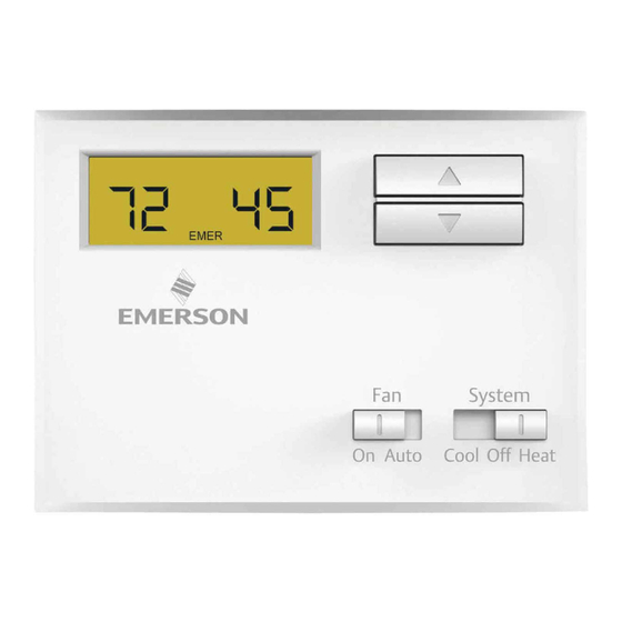
2. THERMOSTAT DETAILS The thermostat buttons and switches (Up arrow) Raises temperature setting. (Down arrow) Lowers temperature setting. FAN switch (ON, AUTO). SYSTEM switch (COOL, OFF, HEAT). System On Auto Cool Off Heat... -
Page 5: Removal Of Your Old Thermostat
3. REMOVING OLD THERMOSTAT 3.1 Turn off power WARNING To prevent electrical shock and/or equipment damage, disconnect electrical power to the system at the main fuse or circuit breaker box, or by flipping a switch at the air handler. Do not restore power until installation is complete. To ensure the power to your heating and cooling system has been turned off, try to turn on heating or cooling by changing the temperature on your old thermostat. - Page 6 3.2 Remove the old thermostat cover Remove the old thermostat’s front cover from the wall base. Some covers pull off easily, while others may need to be released by using a screwdriver. CAUTION Your old thermostat may have a sealed glass tube containing mercury. Be careful not to damage the tube or dispose of the tube in your trash. For safe disposal information, please see Mercury Notice on page 27.
- Page 7 Terminal labeling reference chart If your current terminal has Label the wires with the Terminal function the following letter following letters RH, R, R5, 5 24V Power (Heating) 24V Power (Cooling) W, W1, 4 Heating Relay Y, Y1 Cooling Relay Fan Relay Reversing Valve (for heat pump applications energized in Cool mode)
- Page 8 3.4 Identify jumper wire For terminal RC and RH: On your old thermostat, if… Then, on your new thermostat… Terminal RC and RH are connected Leave the jumper wire in its place with a jumper wire There’s only one R wire (RC, RH, R or R5) Leave the jumper wire in its place coming out of the wall Terminal RC and RH (or 5 or R5) are NOT...
- Page 9 3.5 Remove old thermostat base With all of your wires disconnected and properly labeled, you may now safely remove the thermostat base from your wall. Tip: Worried about having your wires falling into your wall? Keep the wires secure by wrapping the them around a pencil.
-
Page 10: Mounting And Wiring Your New Thermostat
4. MOUNTING AND WIRING YOUR NEW THERMOSTAT 4.1 Install new thermostat base Mount your new thermostat base using the supplied screws. Drill holes and insert wall anchors to secure the thermostat base to the wall, if necessary. 4.2 Connect wires to corresponding terminal blocks Match each labeled wire to it’s corresponding terminal on the mounted thermostat base. - Page 11 4.3 Set switch and advanced wiring W904 Jumper Electric / Gas switch If you have either a gas or oil furnace, set the switch to GAS. If you have an electric furnace, set the switch to ELEC.
-
Page 12: Check Thermostat Operation
4.4 Install the batteries and attach front cover Install the included AAA alkaline batteries and push the front cover on to the thermostat base until it’s secure. 4.5 Turn on power Turn on your power at the source. Congratulations! You’ve completed the thermostat installation process 5. -
Page 13: Fan Operation
5.1 Fan operation If your system does not have a G terminal connection, skip to Heating System. 1. Turn on the power system 2. Move FAN switch to ON position. The blower should begin to operate. 3. Move FAN switch to AUTO position. The blower should stop immediately. 5.2 Cooling system CAUTION To prevent compressor and/or property damage, if the outdoor temperature is below 50°, DO NOT operate the cooling system... -
Page 14: Heating System
1. Mose SYSTEM switch to COOL position. 2. Press to adjust thermostat setting below room temperature. The blower should come on immediately on high speed, followed by bold air circulation 3. Press to adjust temperature setting above room temperature. The cooling system should stop operating. 5.3 Heating system 1. - Page 15 5.4 The thermostat buttons and switches (Up arrow) Raises temperature setting. (Down arrow) Lowers temperature setting. FAN switch (ON, AUTO). SYSTEM switch (COOL, OFF, HEAT). System On Auto Cool Off Heat...
- Page 16 5.5 The display is displayed when the SYSTEM switch is in the HEAT position. displayed (non-flashing) when the SYSTEM switch is in the COOL position. is displayed (flashing) when the compressor is in lockout mode. Displays current temperature. is displayed when the 2 “AAA” batteries are low and should be replaced.
- Page 18 5.6 Operating features Now that you are familiar with the thermostat buttons and display, read the following information to learn about the many features of the thermostat. • SIMULTANEOUS HEATING/COOLING SETPOINT STORAGE — You can enter both your heating and cooling setpoints at the same time.
- Page 19 • TEMPERATURE DISPLAY ADJUSTMENT — Your new thermostat has been accurately set in our factory. However, if you wish, you may adjust your new thermostat temperature display to match your old thermostat. This can be accomplished (within a ±3° range) as follows: 1.
-
Page 20: Specifications
6. THERMOSTAT SPECIFICATIONS ELECTRICAL DATA THERMAL DATA Electrical Rating: Setpoint Temperature Range: 45°F to 90°F (7°C to 32°C) 0 to 30 VAC 50/60 Hz. or D.C. Operating Ambient Temperature Range: 0.05 to 1.0 Amps (Load per terminal) 32°F to 105°F (0°C to 41°C) 1.5 Amps Maximum Total Load (All terminals combined) Operating Humidity Range: 0 to 90% RH (non-condensing) -
Page 21: Troubleshooting
7. TROUBLESHOOTING Reset Operation If a voltage spike or static discharge blanks out the display or causes erratic thermostat operation you can reset the at the same time while moving the SYSTEM switch from OFF to HEAT. thermostat by pressing This also resets the factory defaults. - Page 22 Symptom Possible Cause Corrective Action No Heat/No Cool/No Fan 1. Blown fuse or tripped circuit breaker. Replace fuse or reset breaker. (common problems) 2. Furnace power switch to OFF. Turn switch to ON. 3. Furnace blower compartment door or Replace door panel in proper position to panel loose or not properly installed.
- Page 23 Symptom Possible Cause Corrective Action No Heat 1. Pilot light not lit. Re-light pilot. 2. SYSTEM Switch not set to HEAT. Set SYSTEM Switch to HEAT and raise setpoint temperature above room temperature. 3. Loose connection to thermostat or system. Verify thermostat and system wires are securely attached.
- Page 24 Symptom Possible Cause Corrective Action Heat, Cool or Fan Runs Constantly. 1. Possible short in wiring. Check each wire connection to verify they are not shorted or touching together. No bare wire should 2. Possible short in thermostat. stick out from under terminal screws. Try resetting 3.
- Page 25 Symptom Possible Cause Corrective Action Cooling Cycles Too Fast or Too Slow 1. The location of the thermostat The cycle rate for cooling is fixed and can not (narrow or wide temperature swing) and the size of the Cooling be adjusted. Contact a local service person for System can influence the suggestions.
- Page 26 CONTACT US Customer support: 877.654.9394 or wr.techsupport@emerson.com...
- Page 27 MERCURY NOTICE This product does not contain mercury. However, this product may replace a product that contains mercury. Mercury and products containing mercury must not be discarded in household trash. Refer to thermostat-recycle.org for location to send product containing mercury. FOR CALIFORNIA RESIDENTS Warning: This product contains a chemical known to the state of California to cause cancer and birth defects and other reproductive harm.
Need help?
Do you have a question about the NP110 and is the answer not in the manual?
Questions and answers