Advertisement
TB3 Series Communicating Thermostats
FOR 2-PIPE AND 4-PIPE FAN COIL UNITS
APPLICATION
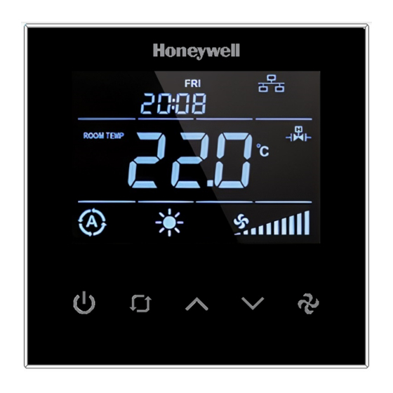
TB3 Series Fan Coil Thermostats are used in individual
rooms or zones in buildings. It is designed for two and
four-pipe fan coil units. TB3 Series has one universal
input as an external sensor (NTC10k) or open/close
contact input, three relay fan outputs, two relay valve
outputs (TB3140), two analog valve outputs (TB3240),
and one EIA-485 (BACnet MS/TP). It controls the fan
coil unit depending on the internal room sensor or
external return sensor temperature.
The following NTC10K sensor and flange are
recommended: VF10-3B65NW and LF-MF
® U.S. Registered Trademark
Copyright © 2022 Honeywell Inc. • All Rights Reserved
INSTALLATION INSTRUCTIONS
CAUTION
CAUTION
• The authorized service must do assembly,
maintenance, diagnostic, and repair. The device's
power supply is 220 VAC (TB3140) and 24V
AC/DC (TB3240), and it has no internal fuse.
• External protection with max C10A (TB3140)
and C5A (TB3240) circuit breakers are required
in all cases.
• Disconnect the power supply before separating
the front plate.
INSTALLATION
• Read these instructions carefully. Failure to follow
them could damage the product or cause a
hazardous condition.
• Check the ratings in the instructions and the product
to ensure the product is suitable for your application.
The Installer must be a trained, experienced service
technician.
• After installation is complete, check out product
operation as provided in these instructions.
• All wiring must agree with applicable codes,
ordinances, and regulations, as specified in
installation wiring diagrams.
• TB3 Series thermostat safety rules are in accordance
with the latest technological developments designed
and manufactured. Adhere to the safety precautions
to avoid injury and property damage.
CAUTION
CAUTION
Power off the supply at circuit breaker or fuse
before installation to avoid fire, shock, or death!
31-00576-01
Advertisement
Table of Contents

Related Manuals for Honeywell TB3 Series


Summary of Contents for Honeywell TB3 Series
- Page 1 • All wiring must agree with applicable codes, ordinances, and regulations, as specified in installation wiring diagrams. • TB3 Series thermostat safety rules are in accordance with the latest technological developments designed and manufactured. Adhere to the safety precautions APPLICATION to avoid injury and property damage.
-
Page 2: Dimensions And Overview
TB3 SERIES COMMUNICATING THERMOSTATS INSTALLATION INSTRUCTIONS DIMENSIONS AND OVERVIEW ORDERING INFORMATION Part number TB3240B/U TB3240W/U TB3140B/U TB3140W/U Digital Outputs (Relay) Fan Control Analog Outputs (0-10 V) Valve Control Relay Output Valve Control Universal Input Colour Black White Black White 24 V AC/DC,... -
Page 3: Product Specification
1 mm Battery for Real Network Security Lithium CR1220 3.3 V Time Clock (RTC) Honeywell hereby expressly states that the TB3 Series Communication Thermostat are not inherently Table 4 Sensors and Inputs protected against all cyber-security risks from the Parameter... -
Page 4: Installation
INSTALLATION NOTE: This Communicating thermostat is suitable for mounting on standard 75 X 75 X 52 mm Honeywell recommended back box as per BS4662:2006 + A1:2009 standard or equivalent. The installation of the device should be performed by an authorized technician. Install the thermostat using the screws provided in the box. - Page 5 TB3 SERIES COMMUNICATING THERMOSTATS INSTALLATION INSTRUCTIONS 4. Pull the power cable and communication cables through the wall box. 5. Connect the wires well according to the wiring diagram. Refer to Wiring Connection on page 6. Fix the base with four screws to the wall box.
-
Page 6: Wiring Connection
TB3 SERIES COMMUNICATING THERMOSTATS INSTALLATION INSTRUCTIONS WIRING CONNECTION There are two types of modulating connection diagrams. Refer to the wiring diagram that corresponds to the series you are using. TB3140 Modulating Connection Diagram Connection Diagram for 4-Pipe Fan Coil Connection Diagram for 2-Pipe Fan Coil... -
Page 7: Users Interface
TB3 SERIES COMMUNICATING THERMOSTATS INSTALLATION INSTRUCTIONS USERS INTERFACE The TB3 thermostat user interface consists of a multi-segment display and five function keys. Name Description Symbol On/Off Switch device state on/off. 1. Mode Selection: To change the modes, press the mode key. The modes available for selection will vary depending on the available pipe system. -
Page 8: Troubleshooting
TB3 SERIES COMMUNICATING THERMOSTATS INSTALLATION INSTRUCTIONS TROUBLESHOOTING Trouble Possible Cause Solution • Use key to set the mode to (Cooling). The system is not • Check if the set point is lower than room temperature. Cooling mode is not cooling, even though the •... -
Page 9: Password Setting
TB3 SERIES COMMUNICATING THERMOSTATS INSTALLATION INSTRUCTIONS PASSWORD SETTING IMPORTANT: It is recommended that a 4-digit pin be set during the first installation. The pin should be kept confidential and should be changed frequently. Users must set a password when the thermostat is installed for the first time or restored to factory settings. The thermostat will display a screen to configure the password in these cases. - Page 10 TB3 SERIES COMMUNICATING THERMOSTATS INSTALLATION INSTRUCTIONS Universal Input (P32 or via BACnet) Parameter Definition Description The device operates based on the value of the internal P32 = 0 Not Used temperature sensor. The device operates based on the value of the external...
-
Page 11: Restore Factory Setting
TB3 SERIES COMMUNICATING THERMOSTATS INSTALLATION INSTRUCTIONS RESTORE FACTORY SETTING FIRMWARE UPDATE (FILE OBJECT) To factory reset the device, press the “On/Off Key,” “Increase/Up Key,” and “Fan Key” together for 5 seconds Upload the binary files for a firmware update to the while the device is on or off. -
Page 12: Configuration Menu Parameters
TB3 SERIES COMMUNICATING THERMOSTATS INSTALLATION INSTRUCTIONS CONFIGURATION MENU PARAMETERS FACTORY NAME OF PARAMETER PARAMETER DEFINITION DEFAULT Hardware Version Device hardware version Firmware Version Device firmware version Setpoint High Limit Range: 5°C to 40 °C (41 °F to 104 °F) 30 °C (86 °F) Setpoint Low Limit Range: 5°C to 40 °C (41 °F to 104 °F) - Page 13 TB3 SERIES COMMUNICATING THERMOSTATS INSTALLATION INSTRUCTIONS FACTORY NAME OF PARAMETER PARAMETER DEFINITION DEFAULT 0: Screen off 1: Room temperature Screen Off State Status 2: Room temperature and off 3: Room temperature and clock This parameter determines the output value of the valve...
- Page 14 TB3 SERIES COMMUNICATING THERMOSTATS INSTALLATION INSTRUCTIONS FACTORY NAME OF PARAMETER PARAMETER DEFINITION DEFAULT MAC Address Range: 001 to 127 Startup Waiting Time Range: 0 to 300 Only valid for TB3240x model. BACnet Parameters Based on BACnet standard MS/TP port configurations are given below;...
- Page 15 TB3 SERIES COMMUNICATING THERMOSTATS INSTALLATION INSTRUCTIONS End Of Line (EOL) Resistor The EOL resistor DIP Switch is located in the top right corner of the TB Series thermostat, behind the front plate. The default is OFF (Left). Turn it to the ON position (Right) to activate the EOL (120 Ohm) resistor.
- Page 16 TB3 SERIES COMMUNICATING THERMOSTATS INSTALLATION INSTRUCTIONS TB3240 Series BACnet Registers Analog Inputs OBJECT READ (R)/ NO OBJECT VALUE FUNCTION DEFAULT NAME WRITE (W) PROPERTY Analog -9.9 °C to 99.9 °C Room This parameter shows the Input #1 (14 °F to 212 °F) Temperature room temperature value.
- Page 17 TB3 SERIES COMMUNICATING THERMOSTATS INSTALLATION INSTRUCTIONS OBJECT READ (R)/ OBJECT VALUE FUNCTION DEFAULT NAME WRITE (W) PROPERTY This parameter adjusts the device's condition to continue when the power Analog Power fails. 0 to 2 Value #7 Failure 0 = Device starts off...
- Page 18 TB3 SERIES COMMUNICATING THERMOSTATS INSTALLATION INSTRUCTIONS OBJECT READ (R)/ OBJECT VALUE FUNCTION DEFAULT NAME WRITE (W) PROPERTY 0 = Off Analog 1 = Low 0 to 3 Fan Status Value #19 2 = Med 3 = High This parameter indicates the alarm state.
- Page 19 TB3 SERIES COMMUNICATING THERMOSTATS INSTALLATION INSTRUCTIONS OBJECT READ (R)/ OBJECT VALUE FUNCTION DEFAULT NAME WRITE (W) PROPERTY This parameter adjusts Analog 5°C to 40 °C Set Point 5 °C the low limit for desired Value #5 (41°F to 104°F) Low Limit (41°F)
- Page 20 TB3 SERIES COMMUNICATING THERMOSTATS INSTALLATION INSTRUCTIONS OBJECT READ (R)/ OBJECT VALUE FUNCTION DEFAULT NAME WRITE (W) PROPERTY If “Universal Input” is Changeover set to “3”, this 11 Analog 10 °C to 25 °C Temperature parameter adjusts 16 °C Value #11 (50 °F to 77 °F)
- Page 21 TB3 SERIES COMMUNICATING THERMOSTATS INSTALLATION INSTRUCTIONS OBJECT READ (R)/ OBJECT VALUE FUNCTION DEFAULT NAME WRITE (W) PROPERTY This parameter indicates the alarm state. 0 = No alarm 23 Analog 1 = Onboard Sensor 0 to 3 Alarm Value #23 Alarm...
- Page 22 TB3 SERIES COMMUNICATING THERMOSTATS INSTALLATION INSTRUCTIONS Binary Values for TB3140x READ (R)/ NO OBJECT VALUE OBJECT NAME FUNCTION DEFAULT WRITE (W) PROPERTY Binary 0 = Stop 0 to 1 Start/Stop Value #1 1 = Start Binary Celsius or 0 = Celsius...
- Page 23 TB3 SERIES COMMUNICATING THERMOSTATS INSTALLATION INSTRUCTIONS SAFE BATTERY REMOVAL 4. Unscrew four screws to remove the back cover from the front plate. 1. Switch OFF the power supply before initiating the TB3 installation. 2. Loosen the bottom screw by turning it anticlockwise 5.
- Page 24 The material in this document is for information purposes only. The content and the product described are subject to change without notice. Honeywell makes no representations or warranties with respect to this document. In no event shall Honeywell be liable for technical or editorial omissions or mistakes in this document, nor shall it be liable for any damages, direct or incidental, arising out of or related to the use of this document.
Need help?
Do you have a question about the TB3 Series and is the answer not in the manual?
Questions and answers