Table of Contents
Advertisement
IMPORTANT: Read safety rules and instructions carefully before operating equipment.
Warning:
This unit is equipped with an internal combustion engine and should not be used on or near any unimproved forest-covered, brush-
covered or grass-covered land unless the engine's exhaust system is equipped with a spark arrester meeting applicable local or state laws (if
any). If a spark arrester is used, it should be maintained in effective working order by the operator. In the State of California the above is required
by law (Section 4442 of the California Public Resources Code). Other states may have similar laws. Federal laws apply on federal lands. A spark
arrester for the muffler is available through your nearest engine authorized service dealer or contact the service department, P.O. Box 361131
Cleveland, Ohio 44136-0019.
PRINTED IN U.S.A.
Operator's Manual
Troy-Bilt LLC, P.O. BOX 361131 CLEVELAND, OHIO 44136-0019
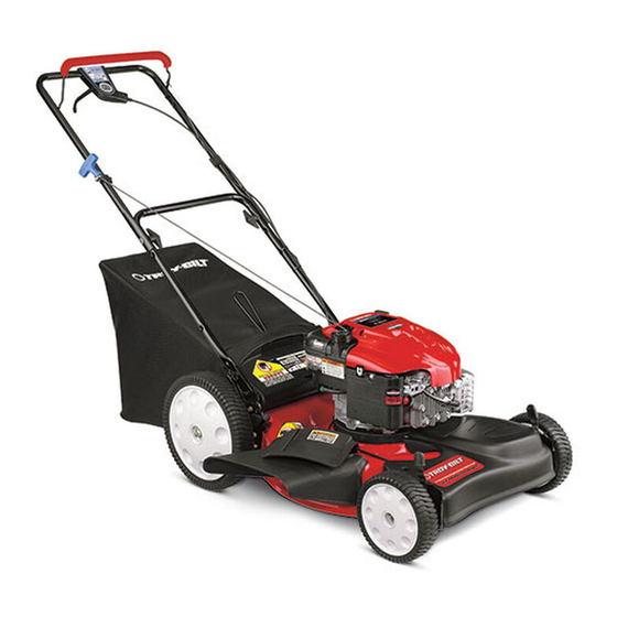
Models 566 & 569
Variable Speed
21" Self Propelled
Mulching Mower
FORM NO.
769-01542.fm
(12/2004)
Advertisement
Table of Contents

Related Manuals for Troy-Bilt 566


Summary of Contents for Troy-Bilt 566
-
Page 1: Box 3 6 1 1 3
(Section 4442 of the California Public Resources Code). Other states may have similar laws. Federal laws apply on federal lands. A spark arrester for the muffler is available through your nearest engine authorized service dealer or contact the service department, P.O. Box 361131 Cleveland, Ohio 44136-0019. Troy-Bilt LLC, P.O. BOX 361131 CLEVELAND, OHIO 44136-0019 769-01542.fm FORM NO. -
Page 2: Table Of Contents
Customer Support Department or an authorized service dealer. Copy the model number here: Copy the serial number here: TROY-BILT LLC P. O. BOX 3 6 1 1 3 1 www.troybilt.com CLEVELAND, OH 44136... -
Page 3: Important Safe Operation Practices
SECTION 1: IMPORTANT SAFE OPERATION PRACTICES WARNING: This symbol points out important safety instructions which, if not followed, could endanger the personal safety and/or property of yourself and others. Read and follow all instructions in this manual before attempting to operate this machine. Failure to comply with these instructions may result in personal injury. -
Page 4: Slope Operation
your footing, release the blade control handle 2. Do not mow slopes greater than 15 degrees as immediately and the blade will stop rotating within shown on the slope gauge. three seconds. 3. Do not mow on wet grass. Unstable footing could 9. - Page 5 9. Never remove gas cap or add fuel while the engine lead to improper performance and compromise is hot or running. Allow engine to cool at least two safety!” minutes before refueling. 4. Mower blades are sharp and can cut. Wrap the 10.
-
Page 6: Slope Gauge
SECTION 2: SLOPE GAUGE Use this page as a guide to determine slopes where you may not operate safely. -
Page 7: Assembling Your Lawn Mower
SECTION 3: ASSEMBLING YOUR LAWN MOWER Removing Unit From Carton Assembling Handle • Remove staples, break glue on top flaps, or cut • Remove grass bag from the unit and set it out of the tape at carton end and peel along top flap to open. way. - Page 8 Assembling Grass Catcher NOTE: If the grass catcher came pre-assembled, Carriage Bolt proceed to the next section. If not, follow the steps below to assemble it before attaching to the mower. Wing Nut Handle • Insert frame into grass bag with the black plastic Mounting Bracket side on the bottom of bag.
- Page 9 Attaching Grass Catcher Converting To Side Discharge • Lift the rear discharge door and place the grass • Make sure the grass catcher is off the unit and the catcher on the pivot rod. Let go of discharge door rear discharge door is closed. Refer to Figure 7. so that it rests on the grass catcher.
-
Page 10: Know Your Lawn Mower
SECTION 4: KNOW YOUR LAWN MOWER Blade Control Handle Read this owner’s manual and safety rules before operating your lawn mower. Compare the illustrations The blade control handle is located on the upper handle in Figure 8 with your lawn mower to familiarize yourself of the mower. -
Page 11: Operating Your Lawn Mower
Remove spark plug Do not prime to restart a warm engine after a short wire from the spark plug and thoroughly inspect shutdown. Model 566 has no primer and requires for any damage. Repair the damage promptly no priming. -
Page 12: Maintaining Your Lawn Mower
Mulching For best results in mowing, keep the cutting height position high until you can determine a suitable height. For effective mulching, do not cut wet grass because it tends to stick to the underside of the deck, preventing Bagging Grass Clippings proper mulching of grass clippings. -
Page 13: Blade Care
Lubrication • Turn mower on its side making sure that the air filter and the carburetor are up. To Remove Blade: • Remove the hex bolt which holds the blade adapter- pulley assembly to the engine crankshaft. See Figure 10 . Remove the pulley assembly and the bell support from Lube the crankshaft. -
Page 14: Service And Adjustments
SECTION 7: SERVICE & ADJUSTMENTS Replacing Drive Belt • Tighten the screw, loosened earlier, to secure the belt tension spring to the transmission, and • Remove two shoulder screws securing the front reassemble the front drive cover. drive cover to the mower deck. See Figure 11. Right Front Left Front Wheel... -
Page 15: Off Season Storage
Height Adjustment Bottom View Lever Upper Adjustment Handle Wheel Drive Clutch Control Figure 15 Figure 14 NOTE: For some people the drive clutch control may not be in a comfortable position. You can adjust the handle by tightening the adjustment wheel. Drive Clutch Control Engine Adjustments The adjustment wheel is located in the drive clutch... -
Page 16: Trouble Shooting
NOTE: • Drain the fuel from the tank by running the engine Fuel stabilizer is an acceptable alternative to until the fuel tank is empty. emptying the tank of fuel in minimizing the formation of • Remove spark plug, pour approximately 1/2 ounce fuel gum deposits during storage. - Page 17 NOTES...
-
Page 18: Illustrated Parts List
SECTION 10: PARTS LIST FOR MODEL SERIES 566 & 569... - Page 19 Model Series 566 & 569 Ref. Ref. Part No. Description Part No. Description 710-0599 TT Screw 1/4-20 x 0.5 738-0507B Shoulder Scr.500 Dia. x.434 736-0270 Bell Washer.265 x 0.75 710-1652 Tt Screw 1/4-20 x.625” 17032A Deflector Chute Adapter 734-04127 Wheel, 12 x 2.125...
-
Page 20: Warranty
Model Series 566 & 569... - Page 21 Model Series 566 & 569 Ref. No Part No. Description Ref. No Part No. Description 731-04204 Deluxe Bail Cover 732-04089A Torsion Spring LH 731-1059 Cable Mounting Cap 732-04090A Torsion Spring RH 731-1058 Control Cover Lower Half 714-0104 Cotter Pin 731-1057...
- Page 22 NOTES...
- Page 23 NOTES;...
- Page 24 MANUFACTURER’S LIMITED WARRANTY FOR: The limited warranty set forth below is given by Troy-Bilt LLC Troy-Bilt does not extend any warranty for products with respect to new merchandise purchased and used in the sold or exported outside of the United States, its United States, its possessions and territories.