
Subscribe to Our Youtube Channel
Related Manuals for Currys Essentials CFSGWH12


Summary of Contents for Currys Essentials CFSGWH12
- Page 1 FREE STANDING GAS COOK ER I N S TRUC T IO N / I N S TAL L ATI ON MA N UA L CF S GWH 12 / C F S GS V1 2...
-
Page 2: Table Of Contents
Contents Unpacking ............................. 4 Product Overview ......................... 5 Front View ...................................5 Top View ..................................5 Control Panel ................................6 Gas Burners .................................6 Before Using Your Cooker ......................6 Using the Hob Burners ......................... 7 Flame Failure Safety Feature..........................7 If the Burner Does Not Light ..........................8 If the Flame is Irregular ............................8 General Guidelines ..............................8 Using the Oven ........................... - Page 3 Installation ..........................21 Adjusting the Feet ........................22 Moving the Cooker ........................22 Stability Bracket ......................... 22 Ventilation Requirements ......................23 Gas Installation ........................... 23 Installation and Service Regulations ..................23 Gas Connection ........................... 24 Installation Relevant to Natural Gas ....................... 24 Installation Relevant to Liquid Petroleum Gas (LPG) ................
-
Page 4: Unpacking
Thank you for purchasing your new Currys Essentials Free Standing Gas Cooker. You must read this manual in order to fully understand how to operate it correctly. This unit MUST be installed by a competent and Registered Engineer (Gas Safe in the UK). -
Page 5: Product Overview
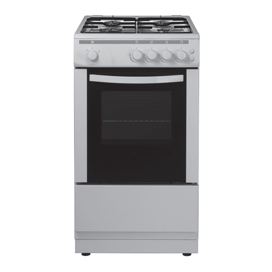
Product Overview Front View Gas Hob Oven Door Control Panel Oven Door Handle Oven Shelf Adjustable Feet Oven Tray Top View Pan Support Standard Burners Large Burner (Fast) Small Burner (Simmer) * All images are for indication only; please refer to your individual unit for actual item. -
Page 6: Control Panel
Control Panel Oven/Grill Control Rear Right Burner (Simmer) Control Rear Left Burner (Standard) Control Oven Light Switch Front Left Burner (Standard) Control Ignition Switch Front Right Burner (Fast) Control Gas Burners The relevant controls adjust the flow of gas through each of the burners. •... -
Page 7: Using The Hob Burners
Using the Hob Burners Choose the control for the burner you want to use. Press the Ignition switch and at the same time press and hold the Burner control in and then turn it anti- clockwise to the maximum position. Release the Ignition switch only, once the burner is lit. -
Page 8: If The Burner Does Not Light
If the Burner Does Not Light If the burner does not light, check that: • The cooker is switched on. • The gas is turned on. • You have held the control in for at least ten seconds. • The ignitors are sparking. If the ignitors are not sparking, they may be dirty or wet. Clean them gently with a small nylon brush such as a toothbrush as shown below. - Page 9 • Pan sizes should be as per the table shown below. Burners Diameter Minimum Diameter Maximum Diameter Small (Simmer) 12 cm 18 cm Standard 14 cm 22 cm Large (Fast) 22 cm 26 cm • Do not use cooking vessels on the hob that overlap the edges of the hob. • The use of a gas cooking appliance results in the production of heat, moisture and products of combustion in the room in which it is installed.
-
Page 10: Using The Oven
Using the Oven First Time Use of the Oven Ensure that nothing has been left in the oven. Remove any packaging, labels and handles or plastic bags. Before connecting the power, use a damp cloth to carefully wipe the inner cavity wall and housing. Clean all the detachable parts in hot, soapy water before using. -
Page 11: Flame Failure Safety Feature
Flame Failure Safety Feature The flame supervision device (FSD) probe cuts off the gas supply to the oven burner if the flame is blown out. When lighting the burner, hold the control in for approximately 10 seconds after the burner has lit. Releasing the control too soon will extinguish the flame. -
Page 12: Preheating
Preheating When you need to preheat the oven, we recommend you do so for 10 minutes. For recipes needing high temperatures, e.g. bread, pastries, scones, soufflés etc., best results are achieved if the oven is preheated first. For best results when cooking frozen or cooked chilled ready meals always preheat the oven first, unless the cooking instructions advise you otherwise. -
Page 13: Using The Grill
Using the Grill When using the grill, the grill deflector must be used. The grill deflector is designed to protect the control panel controls and buttons when using the oven in Grill mode and to keep the door open the specified distance. • Please use this Grill Deflector in order to avoid heat damaging the control panel and the buttons when the oven is in Grill mode. -
Page 14: Cooking With The Grill
When turning the grill off, turn the control in a anti-clockwise direction so that the control shows the OFF (O) position in line with the marking on the control panel. • If the grill burner does not light within 15 seconds, turn the control off and wait for at least 90 seconds before trying again. -
Page 15: Cleaning Instructions
Cleaning Instructions Before you start cleaning your cooker, please: • Read the cleaning instructions and the “Safety Warnings” sections. • Turn the cooker off at the wall and disconnect the plug from the socket. • Allow the cooker to cool fully before cleaning. • Do not use a steam cleaner. -
Page 16: Cleaning The Gas Hob
Cleaning the Gas Hob Maintenance Period Description Daily • Clean the gas hobs as per the cleaning instructions. Monthly • Remove all burner parts, and clean using a non-abrasive detergent. Rinse in cold water, dry thoroughly, and replace. • Clean the ignitor and probe carefully, using a toothbrush. Every year • Contact your local authorized gas Service Agent to perform a thorough check on all gas components on the gas cooker. -
Page 17: Hob Controls (Gas Taps)
Hob Controls (Gas Taps) If you have problems with the hob controls (gas taps), call your Authorised Service Centre. These parts are NOT user serviceable. Removing the Oven Door • Ensure the door has cooled down. • Take care when handling glass. The oven door can easily be removed as follows: Open the door completely. -
Page 18: Replacing The Oven Lamp
Replacing the Oven Lamp Ensure that the cooker is switched off before replacing the lamp to avoid the possibility of electric shock. Let the oven cavity cool down. • Remove the glass lens by turning anti-clockwise. • Unscrew and replace the bulb with a new one suitable for high temperatures (300°C). -
Page 19: Hints And Tips
Hints and Tips Problem Possible Solutions My hob burner does • Check the cooker is switched on. not light • Check the gas supply valve is turned on and the supply to the house is working. You should hear the gas when you press and turn a burner control on. • The ignitors may be dirty. -
Page 20: Specifications
Specifications Model CFSGWH12 / CFSGSV12 Rated Voltage 230 - 240 V Rated Frequency 50 Hz Overall Dimension (W x D X H) 500 x 600 (640 to handle) x 900 - 930 (foot adjustment) mm Usable Volume 50 Litres Oven Lamp Features and specifications are subject to change without prior notice. -
Page 21: Installation
Installation • The cooker must be installed by a competent and Gas Safe Registered Engineer (in the UK) and in compliance with local safety and building regulation safety standards. • The cooker may be located in a kitchen, a kitchen/diner or bed-sitting room in accordance with the latest editions of BS6172, BS5440-2 and BS6891, but not in a room containing a bath or shower. -
Page 22: Adjusting The Feet
Adjusting the Feet Your oven stands on 4 adjustable feet. When the oven is placed where it will be used, check if the oven is level. If it is not level, you can adjust by turning the feet clockwise if required. It is possible to raise the appliance a maximum of 30mm by the feet. -
Page 23: Ventilation Requirements
Ventilation Requirements • This appliance is not connected to a combustion products evacuation device. It should be installed and connected in accordance with current installation regulations. Particular attention should be given to the relevant requirements regarding ventilation. • The appliance should be installed in a room or space with an air supply in accordance with the latest edition of BS5440-2. -
Page 24: Gas Connection
Gas Connection The installation of the cooker to Natural Gas or LP Gas must be carried out by a Gas Safe registered engineer. Installers must take account of the provisions of the relevant British Standards Code of Practice, the Gas Safety Regulations and the Building Regulations. -
Page 25: To Connect The Gas Supply
To Connect the Gas Supply: Connect the gas supply to the right gas inlet at the rear of the cooker. The gas hose must hang in a “U” behind the cooker. Undertake a full gas tightness test. To avoid damage to the appliance gas rail inlet pipe tighten the fittings using two suitable spanners. Using a suitable leak detection fluid solution check each gas connection one at a time by brushing the solution over the connection. -
Page 26: Replacement Of Burner Injectors
Replacement of Burner Injectors This section is to be used by only a Safe Gas Regisered Engineer (in the UK). Contact a Safe Gas Regisered Engineer to change the Hob Injectors. It is illegal to attempt to change the Hob Injectors yourself. Select the injectors to be replaced according to the “Table for the choice of the injectors”. -
Page 27: To Replace The Oven/Grill Injectors
To Replace the Oven/Grill Injectors Removal of the Grill Burner Injector The grill injector can be accessed by removing the single screw on the tip of the burner (as shown). Remove the screw and pull Screw the grill burner towards the front of the cooker, the injector will be revealed on the rear surface of the cavity. -
Page 28: Lubrication Of The Gas Taps
Table for the Choice of the Injectors Natural Gas Burner Injector Values (Total consumption 981 lt/h) G30 / G31 G 20 According to the Gas Type (Total Power 10.3 kW) 28-30 mBar 20 mBar Injector 0.850 1.150 Large Burner (Fast) Nominal Rating Consumption 218.1 gr/h... -
Page 29: Electrical Connection
Electrical Connection • This cooker is fitted with a BS1363 moulded plug. The mains plug must remain accessible when the cooker is in its place of use. • If the installation requires any alterations to the domestic electric system, this must be performed by a qualified electrician. -
Page 30: Safety Warnings
Safety Warnings Installation Operation and Maintenance • This appliance should be installed in accordance • This appliance is NOT intended for use by persons with the regulations in force and only used in a (including children) with reduced physical, sensory well ventilated space. - Page 31 • CAUTION: This appliance is for cooking purposes only. It must not be used for other purposes, for example room heating. • CAUTION: The use of a gas cooking appliance results in the production of heat, moisture and products of combustion in the room in which it is installed.
-
Page 32: Small Burner Ring
If you require a replacement for any of the items listed below, please quote their corresponding part numbers: Replacement Part Part Number Oven Shelf 37015284 Oven Tray 20613041 Grill Rack 37006132 Grill Pan 20643831 Grill Pan Handle 37004739 Pan Supports (Left/Right) 20711046 Stability Bracket 37001966...
Need help?
Do you have a question about the CFSGWH12 and is the answer not in the manual?
Questions and answers