
Subscribe to Our Youtube Channel
Related Manuals for Scantronic I-KP01


Summary of Contents for Scantronic I-KP01
- Page 1 I-KP01 Keypad 2 abc 3 def 4 ghi 5 jkl 6 mno 7 pqrs 8 tuv 9 wxyz Installation Guide...
-
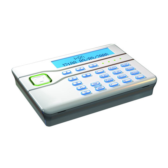
Page 2: Keypad Controls And Displays
I-KP01 Introduction The I-KP01 Keypad is designed to work with the I-ON series of control units. The keypad allows users to set and unset an i-on alarm system and installers to program the system. Keypad Controls and Displays Figure 1 shows the controls and displays available on the keypad. -
Page 3: Technical Specifications
1. Central keyhole. 3. Cable entry. 2. Rear tamper shroud. 4. Fixing holes. Figure 3. Keypad Rear Housing ABCD-ON BACKLIGHT BRIGHT A 12V 0V 1. Sounder. 4. Jumpers for addressing and LED function: 2. Sounder volume control. 4a Addressing 3. -
Page 4: Installation
I-KP01 Installation Siting the Keypad Do site the keypad: Within the area protected by the alarm system. At a convenient height and location for the user. Out of sight of potential intruders. Do NOT site the keypad: Next to electronic equipment, particularly computers, photocopiers or other radio equipment, CAT 5 data lines or industrial mains equipment. -
Page 5: Connect Keypad To End Station
Connect Keypad to End Station CAUTION: Remove all power (both mains and battery) from the control unit before connecting the keypad. Cable Type In general, the control unit requires standard 7/0.2 un-screened alarm cable for wiring to keypads. Screened cable may prove necessary if the installation site has equipment that produces high levels of R.F. -
Page 6: Keypad Addressing
I-KP01 0V 12V 0V 0V 12V 12V A 12V 0V AUX AUX Figure 6. Keypad Connection Keypad Addressing Each keypad connected to an end station must have a unique address. See Figure 4 on page 3 for the position of the addressing jumpers. -
Page 7: Backlight Control
Backlight Control You can control the appearance of the keypad backlights and set/unset LEDs by fitting links over the appropriate jumpers on the keypad pcb (see Figure 4 on page 3 for the position of the jumpers). The jumpers have the following functions:... -
Page 8: Maintenance
I-KP01 Maintenance The only maintenance required is an annual test of the keypad keys and cleaning. Testing the Keys To start testing, make sure the system is idle then: 1. Enter the Installer Menu and select Test. The display shows the Test menu.
Need help?
Do you have a question about the I-KP01 and is the answer not in the manual?
Questions and answers