
Related Manuals for EuroLite LED TMH-10


Summary of Contents for EuroLite LED TMH-10
-
Page 1: User Manual
BEDIENUNGSANLEITUNG USER MANUAL LED TMH-10 Spot 60 W LED Für weiteren Gebrauch aufbewahren! © Copyright Keep this manual for future needs! Nachdruck verboten! Reproduction prohibited! -
Page 2: Table Of Contents
Diese Bedienungsanleitung gilt für die Artikelnummer / This user manual is valid for the article number 51785965 Das neueste Update dieser Bedienungsanleitung finden Sie im Internet unter: You can find the latest update of this user manual in the Internet under: www.eurolite.de 2/30 00054285, Version 1.3... -
Page 3: Einführung
- sich die letzte Version der Anleitung im Internet herunter laden EINFÜHRUNG Wir freuen uns, dass Sie sich für einen EUROLITE LED TMH-10 Spot entschieden haben Wenn Sie nachfolgende Hinweise beachten, sind wir sicher, dass Sie lange Zeit Freude an Ihrem Kauf haben werden. - Page 4 Bitte überprüfen Sie vor der ersten Inbetriebnahme, ob kein offensichtlicher Transportschaden vorliegt. Sollten Sie Schäden an der Netzleitung oder am Gehäuse entdecken, nehmen Sie das Gerät nicht in Betrieb und setzen sich bitte mit Ihrem Fachhändler in Verbindung. Der Aufbau entspricht der Schutzklasse I. Der Netzstecker darf nur an eine Schutzkontakt-Steckdose angeschlossen werden, deren Spannung und Frequenz mit dem Typenschild des Gerätes genau übereinstimmt.
-
Page 5: Bestimmungsgemäße Verwendung
BESTIMMUNGSGEMÄßE VERWENDUNG Bei diesem Gerät handelt es sich um einen kopfbewegten LED-Effektstrahler, mit dem sich dekorative Lichteffekte erzeugen lassen. Dieses Produkt ist nur für den Anschluss an 230 V, 50 Hz Wechselspannung zugelassen und wurde ausschließlich zur Verwendung in Innenräumen konzipiert. Dieses Gerät ist für professionelle Anwendungen, z. -
Page 6: Gerätebeschreibung
Soll das Gerät transportiert werden, verwenden Sie bitte die Originalverpackung, um Transportschäden zu vermeiden. Beachten Sie bitte, dass eigenmächtige Veränderungen an dem Gerät aus Sicherheitsgründen verboten sind. Der Serienbarcode darf niemals vom Gerät entfernt werden, da ansonsten der Garantieanspruch erlischt. Wird das Gerät anders verwendet als in dieser Bedienungsanleitung beschrieben, kann dies zu Schäden am Produkt führen und der Garantieanspruch erlischt. -
Page 7: Installation
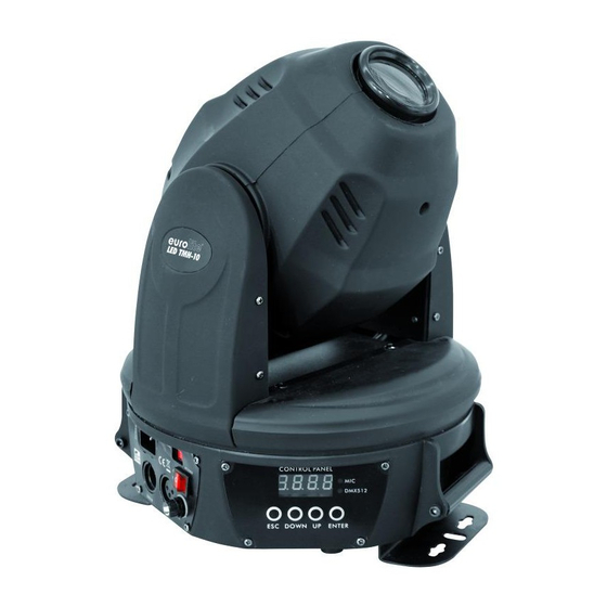
(10) Mode/Esc-Taste (11) Display (12) Up-Taste (13) Down-Taste (14) Enter-Taste (15) DMX-Anzeige (16) Auto/Sound-Anzeige (17) Netzanschluss/Sicherungshalter (18) Netzschalter (19) DMX-Ausgangsbuchse (20) DMX-Eingangsbuchse INSTALLATION Montage BRANDGEFAHR! Achten Sie bei der Installation des Gerätes bitte darauf, dass sich im Abstand von mind. 0,5 m keine leicht entflammbaren Materialien (Deko, etc.) befinden. Das Gerät kann sowohl hängend als auch stehend installiert werden. -
Page 8: Befestigung
Die Aufhängevorrichtungen des Gerätes muss so gebaut und bemessen sein, dass sie 1 Stunde lang ohne dauernde schädliche Deformierung das 10-fache der Nutzlast aushalten kann. Die Installation muss immer mit einer zweiten, unabhängigen Aufhängung, z. B. einem geeigneten Fangnetz, erfolgen. Diese zweite Aufhängung muss so beschaffen und angebracht sein, dass im Fehlerfall der Hauptaufhängung kein Teil der Installation herabfallen kann. -
Page 9: Traversenmontage
Vorgehensweise: Schritt 1: An den beiden Montageplatten des Gerätes befinden sich Löcher zur Installation. Schritt 2: Halten Sie das Gerät mit der Montageplatten an die Stelle, wo es installiert werden soll. Schritt 3: Markieren Sie Ihre Bohrlöcher mit einem Bleistift oder einem geeigneten Werkzeug. Schritt 4: Bohren Sie die Löcher. -
Page 10: Anschluss An Den Dmx-512 Controller / Verbindung Gerät - Gerät
Anschluss an den DMX-512 Controller / Verbindung Gerät – Gerät Achten Sie darauf, dass die Adern der Datenleitung an keiner Stelle miteinander in Kontakt treten. Die Geräte werden ansonsten nicht bzw. nicht korrekt funktionieren. Beachten Sie, dass die Startadresse abhängig vom verwendeten Controller ist. Unbedingt Bedienungsanleitung des verwendeten Controllers beachten. -
Page 11: Bedienung
Über den Netzschalter lässt sich das Gerät ein- bzw. ausschalten. Wenn Sie das Gerät an die Spannungsversorgung angeschlossen haben, nimmt der LED TMH-10 Spot den Betrieb auf. Während des Reset justieren sich die Motoren aus und das Gerät ist danach betriebsbereit. - Page 12 Einstellen der DMX-Startadresse Mit dieser Funktion können Sie die DMX-Startadresse über das Control Board einstellen. Automatischer Program Modus, wenn kein DMX-Signal anliegt Mit dieser Funktion lässt sich das interne Programm aufrufen. Das Gerät lässt sich im Stand-Alone-Betrieb in zwei verschiedenen Geschwindigkeiten betreiben. Wählen Sie "Au01"...
-
Page 13: Dmx-Gesteuerter Betrieb
Bitte vergewissern Sie sich, dass sich die Steuerkanäle nicht mit anderen Geräten überlappen, damit der LED TMH-10 Spot korrekt und unabhängig von anderen Geräten in der DMX-Kette funktioniert. Werden mehrere LED TMH-10 Spot auf eine Adresse definiert, arbeiten sie synchron. - Page 14 Steuerkanal 4 - Farbrad Lineare Farbänderung gemäß der Bewegung des Reglers. Sie können den Farbwechsler an jeder gewünschten Position anhalten. Decimal Hexad. Percentage Eigenschaft 00 07 0% 3% S Offen/weiß 8 15 08 0F 3% 6% S Weiß/violett 16 23 10 17 6% 9% S Violett...
-
Page 15: Reinigung Und Wartung
Steuerkanal 9 - Prisma Decimal Hexad. Percentage Eigenschaft 0 10 00 0C 0% 4% Keine Funktion 11 255 0D FF 4% 100% 3-Facetten-Prisma Steuerkanal 10 - Reset Decimal Hexad. Percentage Eigenschaft 0 149 00 95 0% 58% Keine Funktion 150 200 96 FA 59% 98% Reset... -
Page 16: Sicherungswechsel
Sicherungswechsel Wenn die Feinsicherung des Gerätes defekt ist, darf diese nur durch eine Sicherung gleichen Typs ersetzt werden. Vor dem Sicherungswechsel ist das Gerät allpolig von der Netzspannung zu trennen (Netzstecker ziehen). Vorgehensweise: Schritt 1: Öffnen Sie den Sicherungshalter an der Geräterückseite mit einem passenden Schrauben- dreher. -
Page 17: Introduction
- download the latest version of the user manual from the Internet INTRODUCTION Thank you for having chosen a EUROLITE LED TMH-10 Spot. If you follow the instructions given in this manual, we are sure that you will enjoy this device for a long period of time. - Page 18 Please make sure that there are no obvious transport damages. Should you notice any damages on the A/C connection cable or on the casing, do not take the device into operation and immediately consult your local dealer. This device falls under protection-class I. The power plug must only be plugged into a protection class I outlet.
-
Page 19: Operating Determinations
OPERATING DETERMINATIONS This device is a LED moving-head lighting effect for creating decorative effects. This product is only allowed to be operated with an alternating current of 230 V, 50 Hz and was designed for indoor use only. This device is designed for professional use, e.g. on stages, in discotheques, theatres etc. Lighting effects are not designed for permanent operation. -
Page 20: Description Of The Device
DESCRIPTION OF THE DEVICE Features High performance LED Head Spot • Compact lightweight • Equipped with 1 LED 60 W • 7 brilliant, dichroic colors plus white • Rainbow effect with adjustable speed in both directions • Gobo wheel with 6 rotating gobos plus open •... -
Page 21: Installation
(10) Mode/Esc-button (11) Display (12) Up-button (13) Down-button (14) Enter-button (15) DMX indicator (16) Auto/sound indicator (17) Power supply/fuseholder (18) Power switch (19) DMX-Out socket (20) DMX-In socket INSTALLATION Rigging DANGER OF FIRE! When installing the device, make sure there is no highly-inflammable material (decoration articles, etc.) within a distance of min. -
Page 22: Attachment
The installation of the device has to be built and constructed in a way that it can hold 10 times the weight for 1 hour without any harming deformation. The installation must always be secured with a secondary safety attachment, e.g. an appropriate catch net. This secondary safety attachment must be constructed in a way that no part of the installation can fall down if the main attachment fails. -
Page 23: Mounting On A Trussing System
If the projector shall be lowered from the ceiling or high joists, professional trussing systems have to be used. The projector must never be fixed swinging freely in the room. Mounting on a trussing system Mount the device to your trussing system using the mounting plates and two appropriate clamps. CAUTION! Use 2 appropriate clamps to rig the fixture on the truss. -
Page 24: Connection With The Mains
Occupation of the XLR-connection: If you are using controllers with this occupation, you can connect the DMX-output of the controller directly with the DMX-input of the first fixture in the DMX-chain. If you wish to connect DMX-controllers with other XLR-outputs, you need to use adapter-cables. Building a serial DMX-chain: Connect the DMX-output of the first fixture in the DMX-chain with the DMX-input of the next fixture. -
Page 25: Operation
With the power switch, you can switch the device on and off. After you connected the effect to the mains, the EUROLITE LED TMH-10 Spot starts running. During the Reset, the motors are trimmed and the device is ready for use afterwards. - Page 26 DMX address setting With this function, you can adjust the desired DMX-address via the Control Board. Automatic program mode when there is no DMX signal With this function, you can run the internal program. This mode allows a single unit to run to a factor y installed program in one of two speeds.
-
Page 27: Dmx-Controlled Operation
If you set, for example, the address to channel 13, the device will use the channel 13 to 24 for control. Please, be sure that you don’t have any overlapping channels in order to control each LED TMH-10 Spot correctly and independently from any other fixture on the DMX-chain. - Page 28 Decimal Hexad. Percentage Feature 00 07 0% 3% Open/white 8 15 08 0F 3% 6% White/Purple 16 23 10 17 6% 9% Purple 24 31 18 1F 9% 12% Purple/green 32 39 20 27 13% 15% Green 40 47 28 2F 16% 18% Green/light blue 48 55...
-
Page 29: Cleaning And Maintenance
Control-channel 10 - Reset Decimal Hexad. Percentage Feature 0 149 00 95 0% 58% No function 150 200 96 FA 59% 100% Reset 201 255 FB FF 98% 100% No function Control-channel 11 - Pan-movement with 16 Bit-resolution Control-channel 12 - Tilt-movement with 16 Bit-resolution CLEANING AND MAINTENANCE The operator has to make sure that safety-relating and machine-technical installations are inspected by an expert after every four years in the course of an acceptance test. -
Page 30: Technical Specifications
Procedure: Step 1: Open the fuseholder on the rear panel with a fitting screwdriver. Step 2: Remove the old fuse from the fuseholder. Step 3: Install the new fuse in the fuseholder. Step 4: Replace the fuseholder in the housing. Should you need any spare parts, please use genuine parts.
Need help?
Do you have a question about the LED TMH-10 and is the answer not in the manual?
Questions and answers