Samsung AQ07A1VE Service Manual
Hide thumbs
Also See for AQ07A1VE:
- Owner's instructions manual (26 pages) ,
- Service manual (66 pages) ,
- Installation manual (20 pages)

Related Manuals for Samsung AQ07A1VE


Summary of Contents for Samsung AQ07A1VE
-
Page 1: Table Of Contents
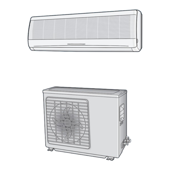
ROOM AIR CONDITIONER INDOOR UNIT OUTDOOR UNIT AQ07A1VE UQ07A1VE AQ09A1VE/B UQ09A1VE/B AQ12A1VE/B UQ12A1VE/B Manual SERVICE AIR CONDITIONER CONTENTS 1. Pre c a u t i o n s 2. Product Specifications 3. Operating Instructions and I n s t a l l a t i o n 4. - Page 2 © Samsung Electronics Co., Ltd. OCT. 1998. Printed in Korea. Code No. DB81-10197A(1)
-
Page 3: Precautions
9 . Keep children away from the unit while it is being re p a i re d . Fig. 1-3 No Kids Nearby! 1 0 . Be sure to clean the unit and its surro u n d- ing are a . Fig. 1-4 Clean the Unit Samsung Electronics... - Page 4 M E M O Samsung Electronics...
- Page 5 2-2 Dimensions 2-2-1 Indoor Unit (Front view) (Remote control) Air out Installation plate (Rear view) 2-2-1 Outdoor Unit (Rear view) (Front view) 145 55 Samsung Electronics...
- Page 6 2-3 Refrigerating Cycle Block Diagram INDOOR UNIT OUTDOOR UNIT Capillary tube Check valve 2-way valve Liquid side Capillary tube Heat Heat exchanger exchanger (Evaporator) (Condenser) Gas side 3-way valve 4-way valve Cooling Heating Compressor Gas leak check point Samsung Electronics...
- Page 7 M E M O Samsung Electronics...
-
Page 8: Operating Instructions And
Without regard to ON/OFF condition in remote controller, use this button to set current time. TIME Adjust the current time using button. (Data can be transmitted after setting up the time) Samsung Electronics... - Page 9 De-ice end by sensing of the pro c e s s i n g 7. FAN SPEED : Manual (3 step), Auto (4 step) time by de-ice Condition. Fan speed automatically varies depending on both the diff e rence between setting and the room temperature . Samsung Electronics...
- Page 10 The LCD also displays the time re m a i n i n g . 11 . 24-Hour ON/OFF Real Setting Ti m e r. : The air conditioner is turned ON at a specified time using ON TIMER Samsung Electronics...
- Page 11 It is harmful to the air conditioner if it is used in the following environments: greasy areas (including areas near machines), salty areas such as coast areas, areas where sulfuric gas is present such as hot spring areas. Contact your dealer for advice. Samsung Electronics...
-
Page 12: Installation Diagram Of Indoor Unit And Outdoor Unit
200mm or more 250mm or more Cut the piping hole sloped slightly Remote control Remote control holder Piping (Liquid) 1/4" Clamper tube 7K/9K BTU Piping(Gas)3/8” Installation plate 12K BTU Piping(Gas)1/2” Installation tube Pipe-connection Vinyl tape Screw Putty Drain hose Samsung Electronics... - Page 13 Result : All inert gas escapes from the indoor unit. • To prevent dirt or foreign objects from getting into the pipes during installation, do NOT remove the caps completely until you are ready to connect the piping. Samsung Electronics...
- Page 14 4. Pass the drain hose through the hole in the wall, making sure that it is sloping downwards, as shown in the illustrations above. The hose will be fixed permanently into position once Shield the whole installation has been tested for gas leaks; refer to page 16 for further details. Drain hose Extension drain hose Samsung Electronics...
- Page 15 Cap Drain B. 3 . Insert Drain plug into Hole , and then connect drain hose to drain plug. • Inside diameter of drain hose is 18mm. Hole C Hole Hole B Drain Plug Cap-Drain A Cap-Drain B Samsung Electronics...
- Page 16 Caution : Burrs not removed may result in leakage of gas. Pipe Reamer Oblique Raughness Burr 3 ) Insert a flare nut into the pipe and modifty flare . Outer diameter A(mm) ø6.35mm ø9.52mm ø12.7mm * Unproper flaring Inclined Surface Cracked Uneven damaged thickness Samsung Electronics...
- Page 17 Liquid pipe side Gas pipe side 6. Open the 2-way valve and 3-way valve completely 2-way valve 3-way valve Outdoor Unit 7. Close the cap of each valve. 8. Check each valve for leakage. 3-10 Samsung Electronics...
- Page 18 7. Stop operation of the air conditioner. 8. Close the 3-way valve, disconnect the pressure gauge, and open the 3-way valve again. 9. Close the cap of each valve. 3-11 Samsung Electronics...
- Page 19 (R-22) for every 1m. (R-22) for every 1m. 3-2-2(j) Flare unt fixing torque Torque (kg-cm) Outter diameter Fixing Torque Final Torque ø 6.35 (9000Btu, 12000Btu) (Liquid Side) ø 9.52 (9000Btu) (Gas Side) ø 12.7 (12000Btu) (Gas Side) 3-12 Samsung Electronics...
- Page 20 At this time, cover the pipe of the indoor 8. Remove the mounting plate for the indoor unit and the other pipe using a cap or vinyl unit and move it to a new location. plug to avoid foreign material entering. 3-13 Samsung Electronics...
- Page 21 M E M O 3-14 Samsung Electronics...
-
Page 22: Disassembly And Reassembly
7) Pull the upper left and right of discharge softly for the outside cover to be pulled out. 8) Pull softly the lower part of discharge and push it up. Caution; Assemble the front panel and fix the hooks of left and right. Samsung Electronics... - Page 23 4) Separate the bush body at the upper side and holder at the rearside. 5) Loosen the two fixing screws of left side. 6) Lifting the heat exchanger up a little to push the up side for separation from the indoor unit. Samsung Electronics...
- Page 24 2) Loosen the fixing three screws and separate the motor holder. 3) Loosen the fixing screw of fan motor. (By use of M3 wrench) 4) Separate the fan motor from the fan. 5)Separate the fan from the left holder bearing. Samsung Electronics...
- Page 25 Fan and Motor 1) Do “1”, above. 2) Loosen two fixing screw, of the front cabinet. 3) Push the brackets of the outer cover to sepa- rate the protection mesh from the rear side of front cabinet. Samsung Electronics...
- Page 26 3) Disassemble the inlet and outlet pipe of com- pressor by welding. 4) Disassemble the inlet and outlet pipe of con- denser by welding 5) Loosen the three bolts of the lower part. 6) separate the compressor. Samsung Electronics...
- Page 27 M E M O Samsung Electronics...
-
Page 28: Troubleshooting
Indoor unit Room sensor Error (open or short) 3 O P E R ATING and TIMER LED blinking (1Hz) Indoor unit heat exchanger temperature sensor Error (open or short) 4 FAN LEA blinking (1Hz) Indoor fan malfunctioning (for spead is Below 38Orpm) Samsung Electronics... -
Page 29: Fault Diagnosis By Symptom
Replace Check PCB pattern . ICO2 10ms Replace main PCB. Is voltage output terminal of D101~D105(IN4007) normal? Are voltage at #30 and #31 of the micom normal? Replace resonator (X501) 100ns Replace IN4007 Is operation normal? Replace micom Samsung Electronics... - Page 30 Is the supply voltage of the fan out of order. be replaced. motor sufficient? Test rod location Normal voltage PCB CN73 Condition Fan operate AC 180V MF-C is out of order Replace MFC Fan motor Fan motor should be is out of order. replaced. Samsung Electronics...
- Page 31 Tap(TB71) and RY 71 terminal No. 3 Outdoor unit is out of order. 1 NO 2 NO Is the room sensor normal register? 10°C 20°C 30°C 17.96k Ω 12.09k Ω 8.3k Ω YES 3 Samsung Electronics...
- Page 32 Is the munber #15 of IC07 (KID65003) LOW? Abnormal IC07 Is the voltage between CN71 #3 and RY71 NO AC198~264? Abnormal RY73 Abnormal 4way valve of Outdoor Unit. or connecting Cable PCB should be replaced. 4 way valve should be replaced or connecting Cable Check. Samsung Electronics...
- Page 33 Voltage at PIN #30 of Remocon Micom change? Voltage at collecter of Q601 or Q602 change? Q601(C4375Y) or Q602(C1623Y) is faulty. IR LED(CL-1L5EU) is faulty. Voltage at pin #26 of micom (IC04) change (INDOOR UNIT)? Receiver module is faulty. Micom (IC04) is faulty. Samsung Electronics...
-
Page 34: Pcb Inspection
The parts should be replaced in the following pro c e d u re . Check for any faulty part. Detach the faulty part. Replace it with a new part. Check the operation of the new part. The repair is completed. Samsung Electronics... - Page 35 1. Indoor unit fan motor is faulty. RMC switch pushed. above 180V~ 1. [FAN] mode 2. Fan speed [Hi] 2. Indoor unit fan motor does not operate. 2. Poor connection of indoor fan motor 3. Continuously operation and connector of RPM sensing (CN43) Samsung Electronics...
-
Page 36: Fault Diagnosis Of Major Parts
Black, Red ∞, O Ω … open or short Abnormal Measure resistance between red wire and each terminal. Stepping Motor Normal Approx. 380Ω at ambient temperature (20°C ~30°C) (UP/DOWN swing motor) ∞, O Ω … open or short Abnormal Samsung Electronics... -
Page 37: Exploded Views And Parts List
6. Exploded Views and Parts List 6-1 Indoor Unit Samsung Electronics... - Page 38 ASS´Y ” DB93-10483A ASS´Y ” DB93-10609A ASS´Y ” DB93-10610A ASS´Y ” DB32-10008D ASS´Y-THERMISTOR ASS´Y DB39-10062V ASS´Y POWER CORD UCP2 DB61-10151A CASE CONTROL DB61-60093A BODY-BUSH HIPS DB94-20030C ASS´Y BACK BODY ASS´Y DB61-40247A HOLDER PIPE HIPS DB70-10618A PLATE HANGER SGCC-M Samsung Electronics...
- Page 39 6-2 Outdoor Unit 18-1 24-1 25-3 25-4 25-5 25-1 25-2 Samsung Electronics...
- Page 40 ASS´Y FLARE NUT 1/4” & 1/2” DB99-90033D ASS´Y FLARE NUT 1/4” & 3/8” 25-1 DB60-30010A FLARE NUT 1/4” 25-2 DB60-30010B FLARE NUT 3/8” DB60-30010C FLARE NUT 1/2” 25-3 DB67-20008A DRAIN PLUG 25-4 DB63-10354A CAP DRAIN 25-5 DB63-10355A CAP DRAIN Samsung Electronics...
-
Page 41: Remote Control
DB68-10790A LABEL DOOR ART 90 PH-M2 SCREW TAP PH-M2 DB67-60061A SPRING BATTERY SUS 304 DB67-60062A SPRING BATTERY SUS 304 DB67-60063A SPRING BATTERY SUS 304 90 250 PE BAG 90 X 250 DB93-40179C ASS’Y PCB REMOCON DB61-40243A HOLDER REMOCON Samsung Electronics... - Page 42 Q’TY CODE NO Specification Description Remark AQ07A1VE AQ09A1VE AQ12A1VE AQ09A1VB AQ12A1VB D B 6 1 - 1 0 1 3 6 A Case-control D B 9 3 - 1 0 4 8 3 A Ass'y MAIN PCB D B 9 3 - 1 0 4 8 5 A...
- Page 43 M E M O Samsung Electronics...
-
Page 44: Block Diagrams
OUTDOOR FAN MOTOR DRIVE 4-WAY VALVE • 4-WAY VALVE DRIVE TEMPERATURE SELECT STEPPING MOTOR STEPPING MOTOR • DRIVE BUZZER SLEEP SELECT • BUZZER DRIVE TIME SETTING DC 5V DC 12V VOLTAGE REGULATOR AC INPUT POWER TRANSFORMER VE : 220-240V/50HZ Samsung Electronics... - Page 45 OUTDOOR FAN MOTOR DRIVE 4-WAY VALVE • 4-WAY VALVE DRIVE TEMPERATURE SELECT STEPPING MOTOR STEPPING MOTOR • DRIVE BUZZER SLEEP SELECT • BUZZER DRIVE TIME SETTING DC 5V DC 12V VOLTAGE REGULATOR AC INPUT POWER TRANSFORMER VE : 220-240V/50HZ Samsung Electronics...
-
Page 46: Pcb Diagrams
8. PCB Diagrams 8-1-1 Main PCB-7000Btu(DB93-10483A) Samsung Electronics... - Page 47 PCB Diagrams PART LIST AQ07A1VE Description CODE NO DESIGN LOCATION Specification F701 DE32-10037A FUSE FST 250V 3.15A F701 DE47-40024A HOLDER-FUSE FH-51H 7.5A IC01 DE13-20008A IC-VOLT REGU KA7812A IC01 DE62-30032A HEAT-SINK AL H25 IC01 DE60-10100A SCREW-PH M3*6 FeFzY IC02 DE13-10016A IC-VOLT REGU...
- Page 48 8-1-2 Main PCB-9000Btu(DB93-10485A) 12000Btu(DB93-10471A) Samsung Electronics...
- Page 49 WIRE SO COPER OP01 DE39-60001A WIRE SO COPER PI0.6 SN T 52MM OP02 DE39-60001A WIRE SO COPER PI0.6 SN T 52MM OP03 DE39-60001A WIRE SO COPER PI0.6 SN T 52MM OP04 DE39-60001A WIRE SO COPER PI0.6 SN T 52MM Samsung Electronics...
- Page 50 PCB Diagrams 8-1-3 Main PCB-9000Btu(DB93-10610A) 12000Btu(DB93-10609A) Samsung Electronics...
- Page 51 PI0.6 SN T 52MM OP01 DE39-60001A WIRE SO COPER PI0.6 SN T 52MM OP02 DE39-60001A WIRE SO COPER PI0.6 SN T 52MM OP03 DE39-60001A WIRE SO COPER PI0.6 SN T 52MM OP04 DE39-60001A WIRE SO COPER PI0.6 SN T 52MM Samsung Electronics...
- Page 52 DIODE SWITCHING 0401-000005 1N4148 C/W DIS & MODULE DB39-20346A UL1007 AWG#26/9 CASE-CENTER PCB UP DB61-10191A PC, BLUE CASE-CENTER PCB LOW DB63-10494A ABS, BLK SEAL DISPLAY UPP DB72-10233A FOAM-PE, BLK SEAL CASE DISPLAY DB72-10220F 30FOAM-PE R-CARBON 2001-000429 RD 1/8TP 102-J Samsung Electronics...
-
Page 53: Wiring Diagrams
9. Wiring Diagrams 9-1 Indoor Unit AQ07A1VE AQ09A1VB AQ09A1VE AQ12A1VB AQ12A1VE Samsung Electr onics... - Page 54 9-2 Outdoor Unit UQ07A1VE CAPACITOR UQ07A1VE: 1.5/25µF X 450VAC UQ09A1VE UQ09A1VB CAPACITOR UQ09A1VE: 1.5/30µF X 450VAC CAPACITOR UQ09A1VB : 1.7/20µF X 450VAC UQ12A1VB UQ12A1VE CAPACITOR UQ12A1VB : 1.5/25µF X 450VAC CAPACITOR UQ12A1VE: 0.9/30µF X 450VAC Samsung Electr onics...
- Page 55 And if you need more information, please see the service bulletin Copyright Tr a d e m a r k s Samsung is a registered trademark and ®œ 1995 by Samsung Electronics Co., Ltd. SyncMaster 17GLi/CMG7387L and MacMaster All rights reserved. Cable Adapter are trademark of Samsung This manual may not, in whole or in part, be Electronics Co., Ltd.
-
Page 56: Schematic Diagrams
10. Schematic Diagrams 10-1 Indoor Unit 10-1-1 AQ07A1VE / AQ09A1VE / AQ12A1VE 1K-1/8W 10-1 Samsung Electronics... - Page 57 10-1-2 AQ09A1VB / AQ12A1VB 10-2 Samsung Electronics...
- Page 58 10-2 Remote Control 10-3 Samsung Electronics...
Need help?
Do you have a question about the AQ07A1VE and is the answer not in the manual?
Questions and answers