
Related Manuals for nord NORDAC SK 700E


Summary of Contents for nord NORDAC SK 700E
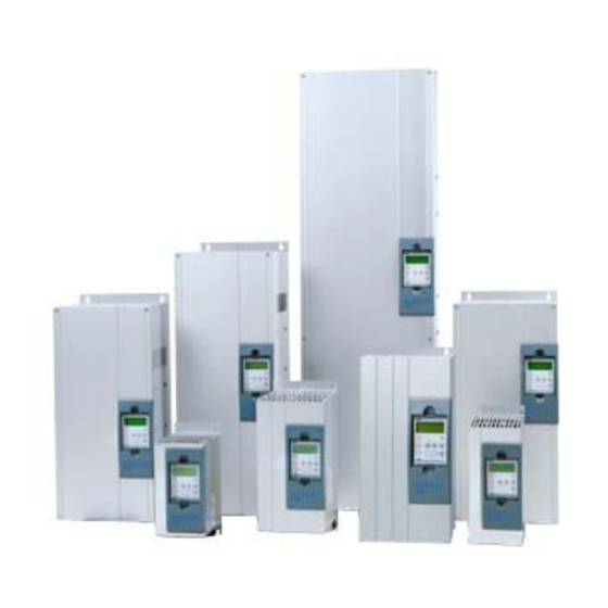
- Page 1 MANUAL NORDAC SK 700E Frequency inverter SK 700E-151-340-A ... SK 700E-163-340-O-VT (1.5kW … 160kW, 3~ 380-480V) SK 700E with option: Parameterbox BU 0700 EN Getriebebau NORD GmbH & Co. KG...
- Page 2 NORDAC SK 700E Operating Manual NORDAC SK 700E frequency inverter Safety and operating instructions for the drive power converter (as per: Low voltage guideline 73/23/EEC ) 1. General information 4. Installation During operation, drive power converters may have, depending on...
-
Page 3: Table Of Contents
Table of contents 1 GENERAL INFORMATION ..........4 3.3 Special extension units ........... 50 1.1 Overview ..............4 3.3.1 PosiCon I/O ............54 3.3.2 Encoder I/O ............55 1.2 Delivery ..............5 1.3 Scope of supply ............5 3.4 Customer I/Os terminals ......... 56 1.4 Safety and installation information ...... -
Page 4: General Information
NORDAC SK 700E Operating Manual General information The series NORDAC SK 700E is the follow-on development of the proven vector series. These devices are characterised by the high modularity and excellent control characteristics. These devices are provided with non-sensor vector current control system which constantly ensures an optimised voltage-to- frequency ratio in combination with a motor model of an three-phase asynchronous motor. -
Page 5: Delivery
Line and output choke, IP 00 (Chapter 2.5/2.6) Interface converter RS 232 → RS 485 (supplemental description BU 0010) NORD CON, PC parameterising software p-box (ParameterBox), external control panel with LCD plain text display, connection cable (supplemental description BU 0040 DE) -
Page 6: Safety And Installation Information
NORDAC SK 700E Operating Manual 1.4 Safety and installation information NORDAC SK 700E frequency inverters are equipment for use in industrial high voltage systems and are operated at voltages that could lead to severe injuries or death if they are touched. -
Page 7: Certifications
An appropriate measure would be the inclusion of a recommended line filter. 1.5 Certifications 1.5.1 European EMC guideline If the NORDAC SK 700E is installed according to the recommendations in this instruction manual, it meets all EMC directive requirements, as per the EMC product standard for motor-operated systems EN 61800-3. -
Page 8: Assembly And Installation
Assembly and installation 2.1 Installation NORDAC SK 700E frequency inverters are available in various sizes depending on the output. When installed in a control cabinet, the size, power dissipation and perm. ambient temperature must be taken into account to prevent device failures. -
Page 9: Dimensions Of The Frequency Inverter
2 Assembly and installation 2.2 Dimensions of the frequency inverter Installation Detail: mounting Width Weight Length depth Device type approx. ∅ Length L2 Width B2 Length L3 SK 700E-151-340-A … 4 kg SK 700E-401-340-A SK 700E-551-340-A 5 kg SK 700E-751-340-A SK 700E-112-340-A 9 kg SK 700E-152-340-A... -
Page 10: Ub Line Filter Up To 22Kw (Accessory)
NORDAC SK 700E Operating Manual 2.3 UB line filter up to 22kW (accessory) An additional external line filter can be installed into the line supply of the frequency inverter to maintain the increased noise suppression level (class B as per EN 55011). -
Page 11: Chassis Line Filter (Accessory)
2 Assembly and installation 2.4 Chassis line filter (accessory) In contrast to the line filter described in Chapter 2.3, the HLD 110 (up to 110kW) has a UL acceptance for the North American market. The interference noise suppression level of class A is achieved with up to a maximum motor cable length of 50m, and class B with motor cables of up to 25m. -
Page 12: Line Choke (Accessories)
NORDAC SK 700E Operating Manual 2.5 Line choke (accessories) To reduce input side current harmonics, additional inductivity can be installed into the line supply to the inverter. These chokes are specified for a maximum supply voltage of 480V at 50/60 Hz. -
Page 13: Output Choke (Accessories)
2 Assembly and installation 2.6 Output choke (accessories) To reduce interference signals from the motor cable or to compensate for cable capacitance in long motor cables, an additional output choke can be installed into the inverter output. Take care during installation that the pulse frequency of the frequency inverter is set to 3-6kHz (P504 = 3-6). -
Page 14: Ub Brake Resistors (Accessory)
NORDAC SK 700E Operating Manual 2.7 UB brake resistors (accessory) During dynamic braking (frequency reduction) of a three phase motor, electrical energy is returned to the frequency inverter. In order to avoid overcurrent cut-off of the frequency inverter, the integrated brake chopper can convert the returned energy into heat by connecting an external brake resistor. -
Page 15: Chassis Brake Resistors (Accessory)
Inverter type Continuous *) Pulse output Connection Resistance Resistor type output (approx.) (approx.) terminals NORDAC SK 700E 200 Ω 1.5 ... 2.2 kW 300 W 3 kW 10 mm SK BR2- 200/300-C 100 Ω 3.0 ... 4.0 kW 400 W... -
Page 16: Wiring Guidelines
NORDAC SK 700E Operating Manual 2.9 Wiring guidelines The frequency inverter has been developed for use in an industrial environment. In this environment, high levels of electromagnetic interference can influence the frequency inverter. In general, correct installation ensures safe and problem-free operation. -
Page 17: Electrical Connections
2 Assembly and installation 2.10 Electrical connections 2.10.1 Line and motor connections WARNING THESE DEVICES MUST BE EARTHED. Safe operation of the devices presupposes that qualified personnel mount and operate it in compliance with the instructions provided in these operating instructions. In particular, the general and regional mounting and safety regulations for work on high voltage systems (e.g. -
Page 18: Mains Connection Up To 22Kw (Pe/L1/L2/L3)
NORDAC SK 700E Operating Manual 2.10.2 Mains connection up to 22kW (PE/L1/L2/L3) No special safety devices are required on the mains input side for the frequency inverter, just the normal mains protection (see technical data) and a master switch/fuse. Connection terminals cross-section: SK 700E-151-340-A ... -
Page 19: Motor Cable (U/V/W/Pe)
2 Assembly and installation 2.10.4 Motor cable (U/V/W/PE) The motor cable must have a maximum length of 150m (Please note also Chapter 8.4 EMC limit value classes). If a shielded motor cable is used, or the metallic cable duct is well earthed, the maximum length of 50m should not be exceeded. For longer cable lengths , additional output chokes must be used. -
Page 20: Control Unit Connection
NORDAC SK 700E Operating Manual 2.10.7 Control unit connection The manner and type of control unit connections are dependent on the options chosen (customer unit / special extension unit). The possible variations are described in Chapter 3.2/3.3. On these pages you will find general data and information on all customer units and special extension units. -
Page 21: Operation And Display
3 Operation and display 3 Operation and display The NORDAC SK 700E basic device is supplied with a blanking cover for the technology unit slot and the basic version has no components for parameterisation or control. Technology units, customer units and special extension units... -
Page 22: Technology Unit
NORDAC SK 700E Operating Manual 3.1 Technology unit (Technology Unit, Option) Technology units are snapped onto the inverter externally. They are for the control or parameterisation of the inverter and for the display of current operating settings.. Technology unit Description Data (SK TU1-...) -
Page 23: Parameterbox
3.1 Technology unit 3.1.1 ParameterBox (SK TU1-PAR, Option) This option is for simple parameterisation and control of the frequency inverter, as well as the display of current operating settings and states. Up to 5 data sets can be stored and managed in this device. Features of the ParameterBox •... - Page 24 NORDAC SK 700E Operating Manual Functions of the ParameterBox Graphic-capable, backlit LCD display for displaying operating values and parameters for the connected LCD display inverter and ParameterBox parameters. Using the SELECTION keys to toggle between the menu levels and menu items.
-
Page 25: Menu Structure
3.1 Technology unit Menu structure The menu structure consists of various levels that are each arranged in a ring structure. The ENTER key moves the menu on to the next level. Simultaneous operation of the SELECTION keys moves the menu back a level. 700E 3,0kW /3 PO S STD Fi/Hz 45.0... - Page 26 NORDAC SK 700E Operating Manual , Summary Language selection The following steps must be carried out to change the language used in the ParameterBox display. The default setting is "German". After the mains supply is switched on, the following displays should appear (varies depending upon output and options).
- Page 27 The frequency inverter can only be completely controlled via the ParameterBox if the parameter >Interface< (P509) is set to the >Keyboard< function (0 or 1) (the factory setting of the NORDAC SK 700E) and the inverter is not enabled via the control terminal.
- Page 28 NORDAC SK 700E Operating Manual Screen layout during parameterisation If the setting of a parameter is changed, then the value flashes intermittently until confirmed with the ENTER key. In order to retain the factory settings for the parameter being edited, both VALUE keys must be operated simultaneously. Even in this case, the setting must be confirmed with the ENTER key for the change to be stored.
- Page 29 3.1 Technology unit Parameter Setting value / Description / Note The first value on the list displayed is scaled using the standardisation factor. If this standardisation P1005 factor varies from a value of 1.00, then the units of the scaled value are hidden in the display. Scaling factor Value range: -327.67 to +327.67;...
- Page 30 NORDAC SK 700E Operating Manual Parameter Setting value / Description / Note P1304 Contrast setting of the ParameterBox display Value range: 0% ... 100%; Resolution 1% Contrast The user can set up a password in this parameter. P1305 If a value other than 0 has been entered in this parameter, then the settings of the ParameterBox or Set password the parameters of the connected inverter cannot be altered.
- Page 31 The connected inverter is not listed in the database of the ParameterBox; no communication can be established. UNRECOGNISED DEVICE • Please contact your Getriebebau Nord dealership. Software version not found. The software of the connected inverter is not listed in the ParameterBox database, no communication can be set up.
- Page 32 NORDAC SK 700E Operating Manual Display Cause • Error Remedy Warnings OVERWRITE DATA? DELETE DATA? These warnings indicate that there is a possibly significant change which needs additional confirmation. MOVE SW VERSION? CONTINUE CANCEL Once the next procedure has been selected, it must be confirmed with the "ENTER"...
-
Page 33: Controlbox
3.1 Technology unit 3.1.2 ControlBox (SK TU1-CTR, Option) This option is used for the parameterisation and control of the frequency inverter. Features • 4-figure, 7 segment LED display • Direct control of a frequency inverter • Display of the active parameter set. •... - Page 34 NORDAC SK 700E Operating Manual Controlling the frequency inverter with the ControlBox The inverter can only be controlled via the ControlBox, if it has not previously been enabled via the control terminals or via a serial interface (P509 = 0).
- Page 35 3.1 Technology unit Parameterisation with the ControlBox The parameterisation of the frequency inverter can be performed in the various operating states. All parameters can always be changed online. Switching to the parameter mode occurs in different ways depending upon the operating states and the enabling source.
- Page 36 NORDAC SK 700E Operating Manual Menu structure with the SimpleBox O perating v alues display P7- - (or operational) P6 - - following m ains O N _ _ _ _ P5 - - P4 - - P0 - -...
-
Page 37: Potentiometerbox
3.1 Technology unit 3.1.3 PotentiometerBox (SK TU1-POT, Option) The PotentiometerBox can be used as a control unit for various functions. Selection can be carried out in parameter P549. In the basic setting direct control of the output frequency within the minimum (P104 =0 Hz) and maximum frequency (P105 = 50 Hz) range is possible. -
Page 38: Rs 232 Box (Sk Tu1-Rs2)
(SK TU1-RS2) The RS 232 technology unit enables simple connection (cable: RS 232, P. No. 78910030) from a NORDAC SK 700E to a PC with serial interface. Communication between PC and frequency inverter can be achieved using the NORD CON Software (Windows). -
Page 39: Profibus 24V Module (Sk Tu1-Pbr-24V)
3.1 Technology unit 3.1.7 Profibus 24V module (SK TU1-PBR-24V) Profibus allows numerous different automation devices to exchange data. PLC's, PC's, operating and monitoring devices can all communicate via a uniform bus in serial bit mode. This Profibus option is supplied via an external 24V DC ±25% connection with voltage. -
Page 40: Interbus Module (Sk Tu1-Ibs)
NORDAC SK 700E Operating Manual 3.1.10 InterBus module (SK TU1-IBS) With InterBus up to 256 participants with different automation devices can exchange data. PLC's, PC's, operating and monitoring devices can all communicate via a uniform bus in serial bit mode. -
Page 41: Customer Units
Profibus DP serial port. SK CU1-PBR 1 x Profibus 1 x multifunction relays CAN bus This unit enables control of the NORDAC SK 700E via 5 x digital inputs the CANbus port. SK CU1-CAN-RJ 2 x CANbus connectors RJ45... - Page 42 NORDAC SK 700E Operating Manual Motor temperature protection - applies to all customer units! - For secure protection against motor overheating, a temperature sensor (PTC Supply voltage +5V thermistor (PTC, PTC) can be connected to any digital input (excluding multi-I/O).
- Page 43 3.2 Customer unit Removal of customer interfaces, up to 22kW: WARNING / NOTE Installation must be carried out by qualified personnel only, paying particular attention to safety and warning instructions. Customer units must not be inserted/removed when live. Switch off the mains voltage, observe the waiting period. Remove the cover grid from the connection area by loosening the 2 screws and levering out the device cover (slot) or simply pull it out.
- Page 44 NORDAC SK 700E Operating Manual Different position of customer units, in devices from 30 kW: WARNING / NOTE Installation must be carried out by qualified personnel only, paying particular attention to safety and warning instructions. Customer units must not be inserted/removed when live.
-
Page 45: Basic I/O
3.2 Customer unit 3.2.1 Basic I/O (SK CU1-BSC, Option) The Customer Unit Basic I/O provides sufficient control terminals for simple control tasks and is therefore an economic solution for many applications. 1 analog input and 3 digital outputs are available to control the frequency inverter. The analog differential input can process positive signals of 0...10V. -
Page 46: Standard I/O
The connected inverter can be controlled and parameterised via the interface RS485. A simple function test of the frequency inverter can be carried out using NORD CON software. Following successful parameterisation, the complete data set can be stored as a file. -
Page 47: Multi I/O
3.2 Customer unit 3.2.3 Multi I/O (SK CU1-MLT, Option) The Multi I/O Customer Unit provides the highest functionality of digital and analog signal processing. 2 analog inputs and 6 digital outputs are available to control the frequency inverter. Both analog inputs can process signals from 0...10V, 0...20mA (4...20mA) or -10V...+10V. -
Page 48: Multi I/O 20Ma
NORDAC SK 700E Operating Manual 3.2.4 Multi I/O 20mA (SK CU1-MLT-20mA, Option) The Multi I/O 20mA Customer Unit provides top functionality for digital and analog signal processing. 2 analog inputs and 6 digital outputs are available to control the frequency inverter. Both analog inputs can process signals from 0...10V, 0...20mA (4...20mA) or -10V...+10V. -
Page 49: Bus Customer Units
3.2 Customer unit 3.2.5 BUS customer units (SK CU1-USS, SK CU1-CAN/-RJ, SK CU1-PBR Option) In addition to data connections, all Bus customer units also provide conventional digital inputs and outputs. By means of a relay contact, brake control and even warnings to another system can be initiated. -
Page 50: Special Extension Units
NORDAC SK 700E Operating Manual 3.3 Special extension units (EXtension Unit, Option) Special extension units are very similar to the customer units; they are however designed for other functions and can only be placed in the lower slots. After insertion, they are automatically identified by the frequency inverter. - Page 51 3.3 Special extension unit Installation of the special extension units Locking pin NOTE Technology unit Installation must be carried out by qualified personnel only, paying particular attention to safety and warning instructions. Customer units must not be inserted/removed when Customer unit live.
- Page 52 NORDAC SK 700E Operating Manual Removal of the special extension units: WARNING / NOTE Installation must be carried out by qualified personnel only, paying particular attention to safety and warning instructions. Customer units must not be inserted/removed when live. Switch off the mains voltage, observe the waiting period.
- Page 53 Customer units must not be inserted/removed when live. The procedure is as above, however no locking lever is present. The module engages when pushed in. Getriebebau NORD Getriebebau NORD GmbH & Co. KG GmbH & Co. KG D-22941 Bargteheide / Germany...
-
Page 54: Posicon I/O
NORDAC SK 700E Operating Manual 3.3.1 PosiCon I/O (SK XU1-POS, Option) The special extension unit (EXtension Unit) PosiCon I/O is a positioning control system integrated in the frequency inverter. Previously programmed positions are reached dynamically and precisely by means of path calculations. -
Page 55: Encoder I/O
3.3 Special extension unit 3.3.2 Encoder I/O (SK XU1-ENC, Option) The special extension (EXtension Unit) encoder I/O offers the possibility of connecting an incremental encoder with a TTL signal level. The incremental encoder must be mounted directly on the motor shaft. This accessory enables highly accurate speed control from standstill to double the rated speed. -
Page 56: Customer I/Os Terminals
NORDAC SK 700E Operating Manual 3.4 Customer I/Os terminals Customer Units / Special Extension Units Desig- Function Data nation Terminal REL 1.1 X3.1.01 X1.1.01 X2.1.01 X4.1.01 X5.1.01 X6.1.01 REL 1.2 X3.1.02 X1.1.02 X2.1.02 X4.1.02 X5.1.02 X6.1.02 REL 2.1 X1.1.03 X2.1.03... -
Page 57: Colour And Contact Assignments For The Encoder
3.4 Klemmebelegung Customer Units / Special Extension Units Desig- Function Data nation Terminal RS485 + X1.4.73 X4.3.73 Electrically isolated input RS485 - X1.4.74 X4.3.74 Transfer rate USS up to 38400 Baud CAN1 H X5.3.75 Transfer rate CAN up to 500 CAN1 L X5.3.76 kBaud... -
Page 58: Commissioning
The frequency inverter is pre-programmed at the factory for standard applications using 4-pole DC standard motors. If another NORD motor is to be used, it can be selected from a motor list in P200. The data is automatically loaded into parameters P201 –... -
Page 59: Basic Operation - Quick Start Guide
4 Commissioning 4.2 Basic operation - Quick start guide ... with ControlBox (Option SK TU1-CTR) The simplest procedure to prepare the frequency inverter for operation is described below. For this operation, jog frequency (P113) is used. The standard setting only has to be changed in one parameter. Display Measure Connect power supply to the frequency inverter. -
Page 60: Minimum Configuration Of Control Connections
NORDAC SK 700E Operating Manual 4.3 Minimum configuration of control connections ... with Basic I/O and ControlBox (Option: SK CU1-BSC + SK TU1-CTR) If the frequency inverter is to be controlled via the digital and analog inputs, this can be implemented immediately in the delivery condition. -
Page 61: Parameterisation
5 Parameterisation 5 Parameterisation There are four switchable parameter sets available during operation. All parameters are always visible. All parameters can be adjusted "online". As there are dependencies between the parameters, it is possible for invalid internal data and operating faults to be Note: generated temporarily. - Page 62 NORDAC SK 700E Operating Manual Availability of the parameters Different parameters can be seen and edited when specific customer units and special extension units are used. The following tables (Chap. 5.1...) list all parameters with information regarding which option they are visible with.
-
Page 63: Parameter Description
5.1.1 Betriebsanzeige 5.1 Parameter description Abbreviations: (P) = Parameter set dependent, these parameters can be set in various ways in the four parameter sets. Frequency inverter FI = 5.1.1 Operating displays Parameter Setting value / Description / Note Available with option P000 Operating displays always visible... -
Page 64: Basic Parameters
NORDAC SK 700E Operating Manual 5.1.2 Basic parameters Parameter Setting value / Description / Note Available in Option P100 Parameter set always visible 0 ... 3 Selection of the parameters sets to be parameterised. 4 parameter sets are available. All parameter set-dependent parameters are identified by (P). - Page 65 5.1.2 Basic parameters Parameter Setting value / Description / Note Available in Option P105 (P) Maximum frequency always visible 0.1 ... 400.0 Hz The frequency supplied by the FI after being enabled and once the maximum setpoint is present, e.g. analog setpoint as per P403, a correspondingly fixed frequency or maximum via the ControlBox.
- Page 66 NORDAC SK 700E Operating Manual Parameter Setting value / Description / Note Available in Option P107 (P) Brake reaction time always visible 0 ... 2.50 s Electromagnetic brakes have a physically-dependent delayed reaction time when actuated. This can lead to load drops during lifting applications, as the brake delays in taking over the load.
- Page 67 5.1.2 Basic parameters Parameter Setting value / Description / Note Available in Option P108 (P) Disconnection mode always visible 0 ... 12 This parameter determines the manner in which the output frequency is reduced after "Blocking" (controller enable low). [ 1 ] 0 = Voltage disable: The output signal is switched off immediately.
- Page 68 NORDAC SK 700E Operating Manual Parameter Setting value / Description / Note Available in Option The limit value 20% of torque current cannot be undershot by a smaller analog setpoint (P400/405 = 2) (with P300 = 1, not below 10%)! 401% = OFF is for switching the torque current limit off! This is also the basic setting for the FI.
-
Page 69: Motor Data / Characteristic Curve Parameters
5.1.3 Motor data 5.1.3 Motor data / characteristic curve parameters Parameter Setting value / Description / Note Available with option P200 (P) Motor list always visible 0 ... 32 / 27 With this parameter, the motor data presets can be changed. The default setting is a 4 pole DC standard motor with the nominal FI power. - Page 70 NORDAC SK 700E Operating Manual Parameter Setting value / Description / Note Available with option cos ϕ P206 (P) always visible 0.50...0.90 The motor cos ϕ is a decisive parameter for the current vector control. ∗∗∗ P207 (P) Star Delta connection always visible 0 ...
- Page 71 5.1.3 Motor data Parameter Setting value / Description / Note Available with option P216 (P) Time boost precontrol always visible 0.0 ... 10.0 s Only with linear characteristic curve (P211 = 0% and P212 = 0%). [ 0 ] Application time for increased starting current. P217 Oscillation damping always visible...
-
Page 72: Control Parameters
NORDAC SK 700E Operating Manual 5.1.4 Control parameters Parameter Setting value / Description / Note Available with option P300 (P) Servo mode ENC POS 0...1 Activates the speed control with speed measurement via the incremental encoder with the special extension units PosiCon or Encoder (SK XU1-ENC, ...-POS). - Page 73 5.1.3 Motor data Parameter Setting value / Description / Note Available with option P315 (P) Field current controller P ENC POS 0...800 % Current controller for the field current. The higher the current controller parameters are set, the more precisely the current setpoint is maintained. Excessively high values for P315 generally lead to high [ 200 ] frequency vibrations at low speeds.
- Page 74 NORDAC SK 700E Operating Manual Parameter Setting value / Description / Note Available with option P326 Ratio encoder ENC POS 0.01...200.0 If the incremental encoder is not mounted directly onto the motor shaft, then the respectively correct transformation ratio of motor speed to encoder speed must be set.
-
Page 75: Control Terminals
5.1.5 Control terminals 5.1.5 Control terminals Parameter Setting value / Description / Note Available with option P400 Analog 1 input function BSC STD 0...18 The FI analog input can be used for various functions. It must be noted that only one of the functions given below is possible at any time. - Page 76 NORDAC SK 700E Operating Manual Parameter Setting value / Description / Note Available with option P401 Mode analog input 1 BSC STD 0 = 0 – 10V limited: An analog setpoint smaller than the programmed adjustment 0% (P402) does 0...3 not lead to undershooting of the programmed minimum frequency (P104).
- Page 77 5.1.5 Control terminals Parameter Setting value / Description / Note Available with option P403 Adjustment 1 100% BSC STD This parameter is used to set the voltage corresponding to the maximum value of the selected function -50.0 ... 50.0 V for analog input 1.
- Page 78 NORDAC SK 700E Operating Manual Parameter Setting value / Description / Note Available with option P410 (P) Minimum frequency analog input 1/2 always visible 0.0 ... 400.0 Hz The minimum frequency that can act on the setpoint via the auxiliary setpoints.
- Page 79 5.1.5 Control terminals Parameter Setting value / Description / Note Available with option P418 (P) Analog 1 output function 0 ... 52 Analog functions An analog voltage (0 to + 10 V) can be taken from the control terminals (max. 5 mA). Various functions [ 0 ] are available, whereby: 0 Volt analog voltage always corresponds to 0% of the selected value.
- Page 80 NORDAC SK 700E Operating Manual Parameter Setting value / Description / Note Available with option P419 (P) Normalising analog output 1 -500 ... 500 % Analog functions P418 (= 0 ... 14, 30) Using this parameter an adjustment can be made to the analog output for the selected operating zone.
- Page 81 5.1.5 Control terminals List of the possible functions of the digital inputs P420 ... P425 Value Function Description Signal No function Input switched off. Enable right FI supplies output signal, rotation field right (if setpoint positive). 0 High → 1 Flank (P428 = 0) Enable left FI supplies output signal, rotation field left (if setpoint positive).
- Page 82 NORDAC SK 700E Operating Manual Value Function Description Signal 2 3 5 Torque current limit Adjustable load limit, the output frequency is reduced when it is analog reached. → P112 2 3 4 5 Actual PID frequency Possible actual value feedback for PID controller...
- Page 83 5.1.5 Control terminals Parameter Setting value / Description / Note Available with option P426 (P) Quick stop time always visible Braking time setting for the emergency stop function, which can be triggered by digital input, bus 0 ...10.00 s control, keyboard or automatically in the case of an error. [ 0.1 ] Emergency stop time is the time for the linear frequency decrease from the set maximum frequency or [ 1.0 ]...
- Page 84 NORDAC SK 700E Operating Manual Parameter Setting value / Description / Note Available with option P434 (P) Relay function 1 BSC STD 0 ... 38 Functions for the signal relay 1 (Control terminals 1 / 2) The settings 3 to 5 and 11 work with 10% hysteresis, i.e. the relay contact closes (fct. 11 opens) when [ 1 ] the limit value is reached and opens (function 11 closes) when a 10% smaller value is undershot.
- Page 85 5.1.5 Control terminals Parameter Setting value / Description / Note Available with option P435 (P) Relay 1 scaling BSC STD Adjustment of the limit values of the relay functions. For a negative value, the output function will be -400 ... 400 % output negative.
- Page 86 NORDAC SK 700E Operating Manual Parameter Setting value / Description / Note Available with option P480 .. - 01 Function Bus I/O In Bits always visible .. - 12 The Bus I/O In Bits are perceived as digital inputs. They can be set to the same functions (P420...425).
-
Page 87: Extra Functions
5.1.6 Fehler! Verweisquelle konnte nicht gefunden werden. 5.1.6 Extra functions Parameter Setting value / Description / Note Available with option P503 Leading function output always visible 0 ... 8 To use the Master function output the source of FI control must be selected in P509. Only the master frequency (setpoint 1 and control word) is transferred with Mode 1, while the actual values selected in [ 0 ] P543, P544 and P545 are transferred in Mode 2. - Page 88 NORDAC SK 700E Operating Manual Parameter Setting value / Description / Note Available with option P505 (P) Abs. minimum frequency always visible 0.0 ... 10.0 Hz Gives the frequency value that cannot be undershot by the inverter. [ 2.0 ] At the absolute minimum frequency, braking control (P434 or P441) and the setpoint delay (P107) are actuated.
- Page 89 5.1.6 Fehler! Verweisquelle konnte nicht gefunden werden. Parameter Setting value / Description / Note Available with option P509 Interface always visible 0 ... 21 Selection of the interface via which the FI is controlled. (P503: Note Master function output!) [ 0 ] 0 = Control terminals or keyboard control **/*** with the Control Box (Option), the Parameter Box (Option, not ext.
- Page 90 NORDAC SK 700E Operating Manual Parameter Setting value / Description / Note Available with option P513 Telegram time-out always visible -0.1 / 0.0 / Monitoring function of the active bus interface. Following receipt of a valid telegram, the next one must 0.1 ...
- Page 91 5.1.6 Fehler! Verweisquelle konnte nicht gefunden werden. Parameter Setting value / Description / Note Available with option P523 Factory setting always visible 0 ... 2 By selecting the appropriate value and confirming it with the ENTER key, the selected parameter range is entered in the factory setting.
- Page 92 NORDAC SK 700E Operating Manual Parameter Setting value / Description / Note Available with option P539 (P) Check output voltage always visible 0 ... 3 This protective function monitors the output current at the U-V-W terminals and checks for plausibility.
- Page 93 5.1.6 Fehler! Verweisquelle konnte nicht gefunden werden. Parameter Setting value / Description / Note Available with option P542 .. - 01 Set analog output 1...2 .. - 02 0.0 ... 10.0 V This function provides the opportunity to control the analog outputs of the FI (depending on the option) independently of its actual operating status.
- Page 94 NORDAC SK 700E Operating Manual Parameter Setting value / Description / Note Available with option P547 (P) Function bus setpoint 2 always visible 0 ... 20 In this parameter, a function is allocated to the output setpoint 2 during bus actuation.
- Page 95 InterBus Technology module SK TU1-CAO SK TU1-DEV SK TU1-IBS Setting USS protocol (Profile "Nord") DS402 profile AC Drives profile Drivecom profile With the use of the internal CANbus (CANnord) via the integrated customer interface (SK Note: CU1-…), the settings in this parameter have no effect. The DS402 profile cannot be activated.
-
Page 96: Positioning
NORDAC SK 700E Operating Manual 5.1.7 Positioning For the description of parameter P6xx please refer to the instructions BU 0710. (www.nord.com) 5.1.8 Information Parameter Setting value / Description / Note Available with option P700 Current fault always visible 0.0 ... 20.9 Actual error present. - Page 97 5.1.8 Information Parameter Setting value / Description / Note Available with option P706 .. - 01 Parameter set last error 1...5 always visible .. - 05 0 ... 3 This parameter stores the parameter set code that was active when the error occurred. Data for the previous 5 faults are stored.
- Page 98 NORDAC SK 700E Operating Manual Parameter Setting value / Description / Note Available with option P717 Current speed immer sichtbar -9999 ... 9999 rpm Displays the actual motor speed calculated by the FI. Positive values are given for rotation in either direction.
- Page 99 5.1.8 Information Parameter Setting value / Description / Note Available with option P733 Phase V current always visible 0.0 ... 500.0 A Displays the actual V phase current. Note: This value can, due to the measurement procedure used even with symmetrical output currents, deviate somewhat from the value in P719.
- Page 100 NORDAC SK 700E Operating Manual Parameter Setting value / Description / Note Available with option P745 ... - 01 Option version always visible ... - 02 ... - 03 0 ... 32767 Array level: [01] Technology unit Software version of the integrated modules [02] Customer unit (only when own processor is present).
-
Page 101: Parameter Overview, User Settings
5.2 Parameter overview, User settings 5.2 Parameter overview, User settings (P) ⇒ Parameter set-dependent, these parameters can be differently adjusted in 4 parameter sets. Setting after commissioning Parameter Factory Name setting OPERATING DISPLAYS (5.1.1) P000 Operating display P001 Select of displayed value P002 Display factor 1.00... - Page 102 NORDAC SK 700E Operating Manual Setting after commissioning Parameter Factory Name setting CONTROL PARAMETERS (5.1.4) Encoder option P300 (P) Servo Mode [On / Off] P301 Incremental encoder P310 (P) Speed controller P [%] P311 (P) Speed controller I [%/ms] P312...
- Page 103 5.2 Parameter overview, User settings Setting after commissioning Parameter Factory Name setting P426 (P) Quick stop time [s] P427 Quick stop on error P428 (P) Automatic starting [Off / On] P429 (P) Fixed frequency 1 [Hz] P430 (P) Fixed frequency 2 [Hz] P431 (P) Fixed frequency 3 [Hz] P432...
- Page 104 NORDAC SK 700E Operating Manual Setting after commissioning Parameter Factory Name setting P537 Pulse disconnection P538 Check input voltage P539 (P) Output monitoring P540 Mode phase sequence P541 Set relays 000000 P542 Set analog output 1 ... 2 P543 (P) Bus - actual value 1...
- Page 105 5.2 Parameter overview, User settings Setting after commissioning Parameter Factory Name setting P623 Digital input 12 P624 (P) Relay 3 function P625 (P) Relay 3 hyst. 1.00 P626 (P) Rel. 3 position P627 (P) Relay 4 function P628 (P) Relay 4 hyst. 1.00 P629 (P) Rel.
- Page 106 NORDAC SK 700E Operating Manual Parameter Name Actual status and displayed values INFORMATION (5.1.8), read only P733 Phase V current [A] P734 Phase W current [A] P735 Speed encoder [rpm] P736 DC link voltage [V] P740 PZD bus in P741...
-
Page 107: Error Messages
6 Error messages Error messages Errors can cause the frequency inverter to switch off. The following options are available to reset a malfunction (acknowledge): By switching mains off and on again, By an appropriately programmed digital input (P420 ... P425 = Function 12), by removing the "enable"... - Page 108 NORDAC SK 700E Operating Manual Display Error Cause Group Detail in Remedy P700 / P701 Inverter overcurrent t limit has triggered, e.g. > 1.5 x I for 60s (please also note E003 P504) Continuous overload at inverter output Overcurrent chopper...
- Page 109 6 Error messages Display Error Cause Group Detail in Remedy P700 / P701 Customer unit type incorrect Database number incorrect Original and reflection are not identical ControlBox error SK-TU1-CTR memory is too small. Replace ControlBox ControlBox error SPI Bus faulty, no communication with ControlBox. E009 Check ControlBox for correct position.
- Page 110 NORDAC SK 700E Operating Manual Display Error Cause Group Detail in Remedy P700 / P701 Slip error switch-off monitoring "Safe stop" was carried out 13.2 Torque limit (P112) was reached, switch-off or increase as necessary. Current limit (P536) was reached, switch-off or increase as necessary.
- Page 111 6 Error messages Display Error Cause Group Detail in Remedy P700 / P701 External RAM error 20.0 E020 Watchdog 20.1 Stack overflow 20.2 Stack underflow 20.3 Undefined opcode 20.4 Protected instruction System error in program execution, triggered by EMC interference. 20.5 Illegal word access Please comply with wiring guidelines in Section 2.9.
-
Page 112: Technical Data
NORDAC SK 700E Operating Manual 7 Technical data 7.1 General Data Function Specification Output frequency 0.0 ... 400.0 Hz Pulse frequency 1.5 to 7.5kW: 3.0 ... 20.0kHz (Standard = 6kHz = Nominal power 100% ED) 11 - 37kW: 3.0 ... 16.0kHz (Standard = 6kHz = Nominal power 100% ED) 45 to 110kW: 3.0 ... -
Page 113: Continuous Thermal Output
7 Technical data 7.2 Continuous thermal output If the pulse frequency (P504) of the power end stage is increased, deviating from the standard settings, this will lead to a reduction in continuous output power. The corresponding trend can be seen in the following diagram. The power loss is approx. 5% of the inverter nominal power (kW). - Page 114 NORDAC SK 700E Operating Manual Size 4 Device type: SK 700E ... -182-340-A -222-340-A Nominal motor power 400V 18.5kW 22.0kW (4-pole standard motor) 460...480V 25hp 30hp Mains voltage 3 AC 380 - 480V, -20% / +10%, 47...63 Hz Output voltage...
-
Page 115: Electrical Data For Ul/Cul Certification
7 Technical data 7.4 Electrical data for UL/cUL certification The data given in this section must be taken into account to comply with UL/CUL certification- Size 1 Device type: SK 700E ..-151-340-A -221-340-A -301-340-A -401-340-A Nominal motor power 380V 1½hp (4-pole standard motor) 460...480V... -
Page 116: Additional Information
NORDAC SK 700E Operating Manual Additional information 8.1 Setpoint processing in the SK 700E Main setpoint sources Frequency master setpoint Funct. digital input: Rotation direction P429-P433 Fixed frequency 1-5 Jog frequency P113 (also with ControlBox) Scaling Scaling P105 Analog input 1... - Page 117 8 Additional information PosiCon special extension unit (option) Setpoint generation POSITION NORDAC SK 700E CONTROLLER Limitation Frequency Min/Max Current Masking Auxiliary ramp limitation frequencies limit setpoint function P600 P105 P112 contro- SETPOINT ller P102,P103 P516- P111 P104 FREQUENCY P106,P107 P413-...
-
Page 118: Process Controller
NORDAC SK 700E Operating Manual 8.2 Process controller The process controller is a PI controller which can be used to limit the controller output. In addition, the output is scaled as a percentage of a master setpoint. This provides the option of controlling any downstream drives with the master setpoint and readjusting using the PI controller. -
Page 119: Process Controller Parameter Settings
8 Additional information 8.2.2 Process controller parameter settings (Example: Setpoint frequency: 50Hz, control limits: +/- 25%) × ⎛ ⎞ Setpoint freq. P415 ≥ ⎜ ⎟ P105 (maximum frequency) [Hz] Setpoint freq. 100% ⎝ ⎠ × ≥ : E.g. 62.5 Hz P400 (Funct. -
Page 120: Electromagnetic Compatibility (Emc)
EMC behaviour in power drives. The limit values correspond to the basic standards EN 50081-1 and EN 50082-1 for radiation and interference resistance. NORDAC SK 700E Frequency inverters are intended exclusively for commercial use. They are therefore not Note: subject to the requirements of the standard EN 61000-3-2 for radiation of harmonics. - Page 121 +10%, -15%; 90% Voltage asymmetries and frequency EN61000-2-4 3%; 2% changes Wiring recommendations for compliance with Class 3 Brake resistor (Accessories) Shield angle BR/+B +UZW/-B 380-480V 50-60Hz Aux. mains NORDAC SK 700E filter BU 0700 EN Subject to technical alterations...
-
Page 122: Maintenance And Servicing Information
8.7 RS 232 PC interface on RJ12 socket To parameterise a NORDAC SK 700E, a PC can be used in addition to the TU ControlBox or ParameterBox. The NORD CON software is required. It can be downloaded free of charge from the Internet (www.nord.com). -
Page 123: Sk 700E Up To 22Kw
8 Additional information Pin assignment RJ 12 Pin assignment SUB-D 9 Function RS 232 / RS 485 RS 232 A_485 B_485 GND_EX TXD_232 RXT_232 +5V_EX When used as RS485 (for USS Bus), the termination resistor of the last subscriber must be switched on NOTE: using the DIP switch next to the RJ12 socket. -
Page 124: Keyword Index
NORDAC SK 700E Operating Manual Keyword index Accessories ........5 DC standard motor ....... 69 Language selection ...... 26 Additional parameters ....87 Delivery condition ......60 Lifting equipment with brake ..66 Analog output ....... 85 DeviceNet ........39 Line choke ........ - Page 125 9 Keyword index Parameter loss ......108 Reference voltage ......20 Technical data ......112 Parameter overview ....101 Relay ..........84 Technology unit ......5, 21 ParameterBox ......23 RJ12 pin assignment ....123 Temperature sensor ..... 42 ParameterBox error messages ..30 RJ12 socket .......
-
Page 126: Representatives / Branches
Co.Ltd. Singapore / Singapur 地址:苏州工业园区长阳街510号 NORD Gear Pte. Ltd. NORD Gear Corporation 800 Nord Drive / P.O. Box 367 33 Kian Teck Drive, Jurong No. 510 Changyang Street, USA - Waunakee, WI 53597-0367 Singapore 628850 Suzhou Ind. Park, Jiangsu, China. - Page 127 Fax: +41-71-388 99 15 Fax: +46-8-594 114 14 Fax: +34-93-7233147 info@nord-ch.com info@nord-se.com info@nord-es.com Ukraine / Ukraine Turkey / Türkei NORD-Remas Redüktör San. ve Tic. Ltd. GETRIEBEBAU NORD GmbH Sti. Repräsentanz Tepeören Köyü Vasilkovskaja, 1 office 306 TR - 34959 Tuzla – Istandbul 03040 KIEW Tel.: +90-216-304 13 60...
- Page 128 Fax +49-4532 / 401 - 253 info@nord-de.com www.nord.com North branches South branches Getriebebau NORD GmbH & Co. KG Getriebebau NORD GmbH & Co. KG Rudolf- Diesel- Str. 1 ⋅ 22941 Bargteheide Katharinenstr. 2-6 ⋅ 70794 Filderstadt- Sielmingen Telefon 04532 / 401 - 0...
Need help?
Do you have a question about the NORDAC SK 700E and is the answer not in the manual?
Questions and answers