Table of Contents
Advertisement
Installation, Operation,
and Maintenance
C-Series
Cassette Indoor Units
Models: 4MUC4518A10N0A, 4MUC4524A10NA, 4MUC4530A10N0A, 4MUC4536A10N0A, 4MUC4542A10N0A,
4MUC4548A10N0A
Only qualified personnel should install and service the equipment. The installation, starting up, and
servicing of heating, ventilating, and air-conditioning equipment can be hazardous and requires specific
knowledge and training. Improperly installed, adjusted or altered equipment by an unqualified person could
result in death or serious injury. When working on the equipment, observe all precautions in the literature
and on the tags, stickers, and labels that are attached to the equipment.
May 2015
SAFETY WARNING
MS-SVX039A-EN
DB68-05139A(1)
Advertisement
Table of Contents

Subscribe to Our Youtube Channel
Related Manuals for Ingersoll-Rand 4MUC4518A10N0A


Summary of Contents for Ingersoll-Rand 4MUC4518A10N0A
- Page 1 Installation, Operation, and Maintenance C-Series Cassette Indoor Units Models: 4MUC4518A10N0A, 4MUC4524A10NA, 4MUC4530A10N0A, 4MUC4536A10N0A, 4MUC4542A10N0A, 4MUC4548A10N0A SAFETY WARNING Only qualified personnel should install and service the equipment. The installation, starting up, and servicing of heating, ventilating, and air-conditioning equipment can be hazardous and requires specific knowledge and training.
-
Page 2: Important Environmental Concerns
Introduction Read this manual thoroughly before operating or servicing this unit. WARNING Warnings, Cautions, and Notices Proper Field Wiring and Grounding Required! Safety advisories appear throughout this manual as Failure to follow code could result in death or serious required. Your personal safety and the proper operation of injury. -
Page 3: Table Of Contents
Table of Contents Model Number Description ..........4 Preparing for Installation . -
Page 4: Model Number Description
Model Number Description Digit 1: Refrigerant 4 = R-410A Digit 2: Brand name M = Mini-split indoor unit Digit 3: System type U = Universal match heat pump Digit 4: Configuration type C = 4-way cassette Digit 5: Reserved for future use 4 = Standard model Digit 6: Connection type 5 = Flare... -
Page 5: Preparing For Installation
Preparing for Installation Accessories In addition to product literature, the following accessories are supplied with this unit. The type and quantity may differ, depending on the model. Flexible hose Template Insulation A Insulation B Insulation C clamp Flexible hose Cable tie Conduit bracket Note: The required panel is not included with the indoor unit. -
Page 6: Unit Dimensions
9.5 (240) Sub duct connection 10.6 (270) 11.8 (300) Model 4MUC4530A10N0A 4MUC4536A10N0A 4MUC4542A10N0A Dimension/Weight/Diameter 4MUC4518A10N0A 4MUC4524A10N0A 4MUC4548A10N0A 8 (204) 11.3 (288) 10 (253) 13.3 (337) Net dimension 33 x 8 x 33 (840 x 204 x 840) 33 x 11.3 x 33 (840 x 288 x 840) Net weight 34.2 lb (15.5 kg) -
Page 7: Service Clearances
Preparing for Installation Service Clearances 59 (1500) minimum 0.67 (17) 0.79 (20) Obstruction Model 4MUC4530A10N0A Clearance 4MUC4536A10N0A 4MUC4518A10N0A 4MUC4542A10N0A 4MUC4524A10N0A 4MUC4548A10N0A 10 (253) 13.3 (337) MS-SVX039A-EN... -
Page 8: Installation
Installation Review “Installation Considerations” before proceeding with installation. Follow the procedures in these sections in the order given. Mounting the Unit If the ceiling is already constructed, piping must be laid into position before placing the unit inside the ceiling. CAUTION Avoid equipment damage and personal injury! Ensure that the ceiling is strong enough to support the weight of the indoor unit. -
Page 9: Purging The Unit
Installation 0.79 in. (20 mm) Indoor unit Ceiling 0.67 in. (17 mm) Gauge Adjust the level of the unit with a leveler. Purging the Unit The unit is shipped from the factory with a holding charge of nitrogen. All of this gas must be purged from the unit. -
Page 10: Installing Refrigerant Piping
Installation Installing Refrigerant Piping Connect field-supplied piping using flared connections (not supplied) or by brazing. The large unit port is for gas refrigerant; the small one is for liquid refrigerant. Cut or extend field-supplied piping as needed. Use the following procedures. NOTICE System Failure! If brazing is used for pipe connections, a nitrogen purge is required to prevent the formation of... - Page 11 Installation Conventional flare tool R-410A clutch type Clutch type Wing nut type 0–0.020 in. 0.04–0.06 in. 0.06–0.08 in. 3. Attach the yoke to the flaring bar, centering the conical part over the end of the pipe that is extending above the flaring bar. 4.
-
Page 12: Leak Testing Pipe Connections
Installation Leak Testing Pipe Connections WARNING Confined Space Hazards! Do not work in confined spaces where refrigerant or other hazardous, toxic or flammable gas may be leaking. Refrigerant or other gases could displace available oxygen to breathe, causing possible asphyxiation or other serious health risks. Some gases may be flammable and or explosive. -
Page 13: Installing The Drain System
Installation Installing the Drain System 1. Push the supplied drain hose as far as possible over the drain hose port. • Do not apply excessive force to the piping on the unit side when connecting the drain hose. • Drain hose port locations differ depending on the unit type. Drain connection Drain hose Drain hose port... - Page 14 Installation • Do not install the hose with an upward gradient after the connection port or leaks will result. • The hose should not be allowed to hang loose from its connection to the unit. Fasten the hose to a wall, frame or other support as close to the unit as possible. 3.28–4.92 ft (1–1.5 m) •...
-
Page 15: Centralized Drainage
Installation Centralized Drainage If the installation requires more than three indoor units, install the main air vent at the front of the indoor unit that is farthest from the main drain. It may be necessary to install individual air vents to prevent water flowing back to each indoor unit. See figure below. -
Page 16: Insulation
Insulation After determining that there are no leaks in the refrigerant pipes or drainage hose, insulate them as described in these sections. Refrigerant Pipes 1. Use the table below to select the insulation type for each pipe size. Insulation Type Standard conditions High humidity conditions (86°F [30°C], 85%) -
Page 17: Wiring The Unit
Wiring the Unit Observe the following precautions when making electrical connections. WARNING Hazardous Voltage! Disconnect all electric power, including remote disconnects before servicing. Follow proper lockout/tagout procedures to ensure the power can not be inadvertently energized. Failure to disconnect power before servicing could result in death or serious injury. NOTICE Use Copper Conductors Only! Unit terminals are not designed to accept other types of conductors. - Page 18 Wiring the Unit Figure 1. Wiring diagram Outdoor unit Communication cable Circuit breaker Disconnect Indoor unit Grounding Power cable Figure 2. Wiring terminals Indoor unit L1 L2 L1 L2 1(L) 2(N) Cable ties Indoor power Main power cable Communication cable Cable clamp Outdoor unit MS-SVX039A-EN...
-
Page 19: Electrical Conduit Installation
Wiring the Unit Electrical Conduit Installation A conduit bracket must be installed to secure the conduit, as illustrated in Figure 3, p. Figure 3. Conduit bracket installation Push Click MS-SVX039A-EN... -
Page 20: Configuration
Configuration All indoor units are factory configured. If modifications are required, The Technician Utilities Tool (TUT) is strongly recommended. However, any of the following devices can be used: • Technician Utilities Tool (TUT) (instructions follow) • Wireless Remote Control (instructions follow) •... -
Page 21: Using The Wireless Remote Control
Configuration Using the Wireless Remote Control To change system configurations using the Wireless Remote Control, follow this procedure: 1. Remove the batteries from the remote control, and re-insert them while pressing the Temp+ and Temp- buttons simultaneously (refer to Figure 4, p. 21). -
Page 22: The 2-Digit Segments
Configuration The 2-Digit Segments Each 2-digit segment is differentiated from the others by a combination of operation mode and timer on/off icons as shown in Figure Use digit 2 (shown in red in Figure 5) to set the wireless remote to Installation Option #1. Figure 5. -
Page 23: Installation Option #1
Configuration Installation Option #1 When digit 2 is set to a value of “2, ” the options shown in Table 1 can be set to the values in the right column. Table 1. Installation option #1: Digit 2 = 2 Display screen Digit... - Page 24 Configuration Table 1. Installation option #1: Digit 2 = 2 (continued) Display screen Digit (mode and On/Off) Option description Set digit to... 0: Disabled External control 1: On/Off control 2: Off-only control External control output Thermal on External control output Operation on Not available.
-
Page 25: Operation
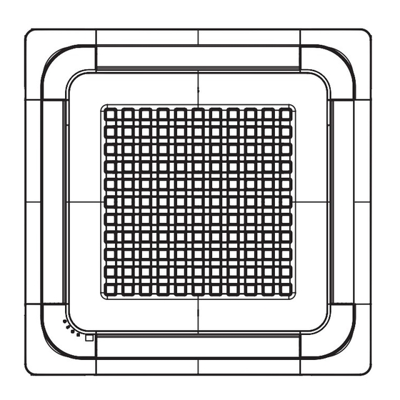
Operation Familiarize yourself with the unit components and operating tips before operating the unit. Components Air flow blade Air intake Air filter (under grill) Display Defrost indicator Filter reset indicator Power indicator (On/Off) Timer indicator Remote control sensor Note: Your unit and display may look slightly different from the illustration shown above, depending on your model. -
Page 26: Internal Protections
Operation Internal Protections Internal protections operate if an internal fault occurs in the unit. Type Description Cold air dump The internal fan will be off to prevent a cold air dump when the heat pump is in defrost mode. Defrost cycle The internal fan will be off to prevent a cold air dump when the heat pump is in defrost mode. -
Page 27: Cleaning The Grill And Air Filter
Operation Cleaning the Grill and Air Filter 1. Open the blades on the left and right sides of the grill. Press both levers and pull the grill downward. Two safety clips are mounted to the grill to prevent it from dropping. 2. -
Page 28: Periodic Maintenance Checks
Operation 4. Clean the grill and air filter with a vacuum or soft brush. If the dust is too thick, rinse them under running water and dry in a well-ventilated area. Note: Drying the air filter in a confined or humid area may cause odors to develop. If odors occur, re-clean and dry it in a well-ventilated area. -
Page 29: Troubleshooting
Troubleshooting Refer to Table 3 for solutions to common problems and to Table 4, p. 30 for a list of alarm conditions with corresponding error codes and LED behavior. Table 3. Solutions to common problems Problem Solution The unit does not operate The anti-short cycle timer prevents the unit from operating immediately to keep immediately after restarting it. -
Page 30: Error Code
Troubleshooting If an error occurs, one of more of the LEDs on the display (see “Components” for their location) will flicker. As a protection strategy, the unit stops operating (and the LED turns off). If the unit is turned on before the problem is resolved, the LED will resume flickering and the unit will stop operating again. -
Page 31: Warranty For Trane C-Series Ductless Systems And Related Accessories
Warranty For Trane C-Series Ductless Systems and Related Accessories Warranty For Trane C-Series Ductless Systems and Related Accessories Products Covered This warranty is extended by Trane, and applies to all Trane C-Series Ductless Systems and Accessories for these products which are sold by Trane and applied in accordance with Trane specifications. - Page 32 The manufacturer optimizes the performance of homes and buildings around the world. A business of Ingersoll Rand, the leader in creating and sustaining safe, comfortable and energy efficient environments, the manufacturer offers a broad portfolio of advanced controls and HVAC systems, comprehensive building services, and parts. For more information, visit www.IRCO.com.
Need help?
Do you have a question about the 4MUC4518A10N0A and is the answer not in the manual?
Questions and answers