Table of Contents
Advertisement
REFRIGERATOR
RS26**
For the latest information, Please access to our service web site (http://itself.sec.samsung.co.kr)
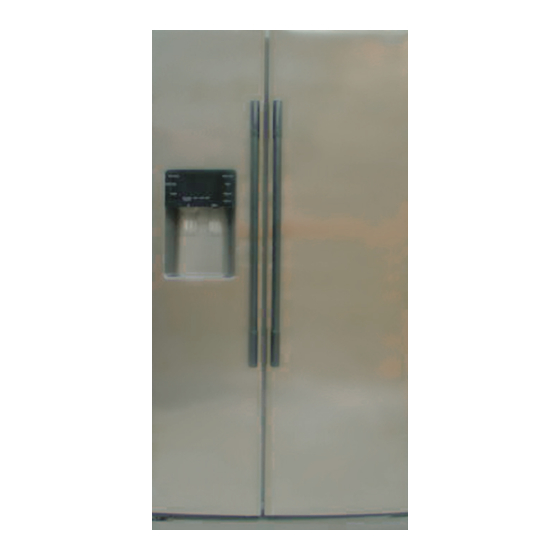
REFRIGERATOR
SIDE BY SIDE
BASIC : RS265BBWP, RS267LBBP
MODEL NAME : RS263BBWP RS265LBBP
RS263BBBB RS265LBWP
RS263BBSH RS267LBSH
RS264ABBP RS264ABRS
RS264ABSH RS264ABWP
RS267BBBB RS269LBRS
RS267BBSH RS267BBRS
MODEL CODE : RS263/264/265/267/269**/XAA
PRODUCT FEATURE
● ● NEW DIGITAL DISPLAY(LED)
● ● TOWER LIGHTING
● ● CONTOUR DOOR/HIDDEN HINGE
● ● CLEAN LOOK DRAWER
● ● TWIN COOLING
● ● HUMAN TOUCH HANDLE
Advertisement
Chapters
Table of Contents


Need help?
Do you have a question about the RS265BBWP and is the answer not in the manual?
Questions and answers
How old is the fridge?