Table of Contents
Advertisement
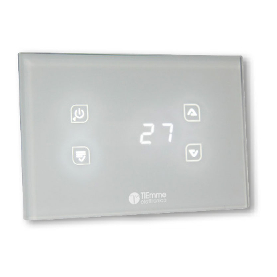
GLH110 Glass
1.
MAIN FEATURES
The GLH110 Temperature Controller manages Wood Fireplaces and Boilers, for heating and domestic hot water production, with the
possibility to integrate it to a Gas Boiler.
Regulations:
EN 60730-1 50081-1
EN 60730-1 A1 50081-2
Technical data
Supply:230 Vac 50 Hz 10%
Absorption:2,5 VA
Outputs Range:5A 250 Vac
Internal fuse:3,15 A
2.
INSTALLATION
Make sure that the Main Power Supply is OFF prior to installing the device
Install the product in a dry environment with proper climatic conditions
Insert a bipolar main switch compliying to local regulations
Avoid coupling the probe cables with these of power
Use for wiring, cables with conductors of appropriate section and in according the rules
Position the probes to detect correctly the temperature
Make sure the probe wires are placed away from direct/indirect flame
3.
ELECTRICAL CONNECTIONS
Code
Connectors
1 – 2
LINE
13 – 14
S1
15 – 16
S2
16 – 17
S3
16 – 17 – 18
3 – 4
P1
5 – 6 – 7
P2
8 – 9 – 10
P3
P4
11 - 12
19 – 16 o 14
PWM1
20 – 16 o 14
PWM2
Temperature Controller
Safety Rules
Read carefully the following safety regulations, in order to prevent accidents
damage to people and things.
Before working on the hydraulic plant, please be aware of the following:
Accident prevention measures
Environmental protection measures
National Institute for Work accidents measures
Recognized prevention measures
This manual is intended for qualified technical staff only
Electrical wiring and connection must be performed by qualified
technicians only
The first installation of the hydraulic plant must be performed expert
personnel
Declaration of Conformity
06055 Marsciano (PG) Italy Tel.+39.075.874.3905; Fax.
+39.075.874.2239info@tiemmeelettronica.it
Mechanical Characteristics
Material: PA
Flush mount Installation:Incasso 3
Modules/ Wall
Dimensions:Flush mount: 132x68x50 mm
Degree of Protection:IP40
Device
Voltage Supply
Fireplace Temperature Probe
Sanitary Boiler Probe / Buffer
Flow Switch
Ambient Probe/Thermostat
Buffer, Manifold
Pump 1
Diverter Valve / Pump 2
Boiler Integration Consent
Service = Thermostat
Service = Grill
Combustion Air Shutter
Pump 2
Control PWM1
Control PWM2
Pag. 1/15
TiEmme elettronica
Installation conditions and Use
Operating Temperature: 0÷40 °C
Storage Temperature:0 ÷ 60 °C
Umidity: 85% @25°C
All the probe inputs and command outputs are controlled
automatically according to the type of hydraulic/plumbing
plant selected.
For electrical connections
you must refer to Chapter 7 and the following paragraphs
concerning the hydraulic/plumbing schematic drawings.
Fig.2 –
Electrical connections
Characteristics
230 Vac 50 Hz 10%
Operating Range: -50°C ÷ 125 °C
NTC 10K Measure: -10 ÷ 110 °C 1°C
NTC 100K Measure: -10 ÷ 300 °C 1°C
PT 1000 Measure: -40 ÷ 300 °C 1°C
Flow switch contact ON/OFF
Operating Range: 0 ÷3 bar / 0 ÷ 3V
230 Vac 5A
230 Vac 5A
Contact in exchange: COM.(9)-N.O.(8) - N.C.(10)
230 Vac 5A
0-5Vdc, Frequency 1Khz, Duty Cycle 0-100%
0CAR6IN019124_Manual_GLH110_Rev_0.3
User Manual
Advertisement
Table of Contents

Related Manuals for TiEmme GLH110


Summary of Contents for TiEmme GLH110
-
Page 1: Main Features
User Manual Temperature Controller MAIN FEATURES The GLH110 Temperature Controller manages Wood Fireplaces and Boilers, for heating and domestic hot water production, with the possibility to integrate it to a Gas Boiler. Safety Rules Read carefully the following safety regulations, in order to prevent accidents damage to people and things. - Page 2 Control Panel: USE AND FUNCTIONS ON/OFF Scroll/Increase Exit the Menu Pump1 Test Service Probes Menu Shutter Manual Start Scroll/Decrease Enter User Menu Pump2 Test Probes Menu Shower Key Fig. 3 Main Screen S1 Probe Temperature S1 Probe Displayed P1 Output Activated S2 Probe Displayed P2 Output Activated S3 Probe Displayed...
- Page 3 PUMP P1 FUNCTIONING TEST When the controller is OFF, prolongued pressure of K3 key: P1 output is activated for as long as the key is pressed and the display will show tSt1 PUMP P2 FUNCTIONING TEST When the controller is OFF, prolongued pressure of K4 key: ...
- Page 4 SOLAR CIRCUIT Buffer Tank Loading: The Solar Manifold Pump is activated: If the Temperature of (S3) >A33 and Δ (S3-S2) > d02 The Buffer Loading is disabled once the Buffer Comfort Thermostat has been reached on S2 (A20). Manifold and Buffer Safety: If the Temperature of the Manaifold (S3) >...
- Page 5 SOLAR Profile On the basis of this profile it is advisable to set the PWM duty cycle parameters as shown below: PWM2 Vmin: U01 >= 15% Vmax: U02 <= 95% In the following conditions the PWM can be setup with the following parameters: ...
- Page 6 Description Cod. U.M. Thermostat to close Air Damper on S1 probe [°C] Antifreeze Thermostat on S1 probe [°C] SAFETY Thermostat on S1 probe [°C] ALARM Thermostat on S1probe [°C] High Temp. Thermostat on high Buffer Tank probe [°C] Manifold Pump Activation Thermostat [°C] ANTIFREEZE Thermostat on manifold probe [°C]...
- Page 7 Enable SHOWER Function Enable ANTISEIZE of Pump1 Abilitazione ANTISEIZE of Pump2 Type of manifold Probe PWM1 Management PWM2 Management Percentage of PWM1 Duty Cycle at Minimum Speed HEATING profile Percentage of PWM1 Duty Cycle at Maximum Speed HEATING profile Percentage of PWM1 Duty Cycle in Antifreeze HEATING profile Percentage of PWM1 Duty Cycle in Safety HEATING profile Percentage of PWM1 Duty Cycle in Antiseize HEATING profile Percentage of PWM1 Duty Cycle in Manual Mode HEATING profile...
- Page 8 Hydraulic Plant 1 (ConF = 1) Hydraulic Plant 2 (ConF = 2) Name Symbol Pins Name Symbol Pins 3 – 4 3 – 4 Fireplace Pump Fireplace Pump 19 – 16 o 14 19 - 16 o 14 PWM1 PWM1 5 –...
- Page 9 Hydraulic Plant 3 (ConF = 3) Hydraulic Plant 4 (ConF = 4) Name Symb Pins Name Symb Pins 3 – 4 3 – 4 Fireplace Pump Fireplace Pump PWM1 19 - 16 o 14 PWM1 19 - 16 o 14 5 –...
- Page 10 Hydraulic Plant 5 (ConF = 5) Hydraulic Plant 6 (ConF = 6) Name Symb Pins Name Symb Pins 3 – 4 3 – 4 Fireplace Pump Fireplace Pump PWM1 19 - 16 o 14 PWM1 19 - 16 o 14 5 –...
- Page 11 Hydraulic Plant 7 (ConF = 7) Hydraulic Plant 8 (ConF = 8) Name Symb Pins Name Symb Pins 3 – 4 3 – 4 Fireplace Pump Fireplace Pump PWM1 19 - 16 o 14 PWM1 19 - 16 o 14 5 –...
- Page 12 * Se P06=3 See Par. 5.11 S1> 75° [A05 Air Damper Hydraulic Plant 9 (ConF = 9) See Par. 5.10 S1> 45° [A09 Service Name Symb Pins * Se P06=3 Hydraulic Plant 10 (ConF = 10) 3 – 4 Name Symb Pins Fireplace Pump...
- Page 13 Hydraulic Plant 11 (ConF = 11) Hydraulic Plant 12 (ConF = 12) Name Symb Pins Name Symb Pins 3 – 4 3 – 4 Fireplace Pump Fireplace Pump PWM1 19 - 16 o 14 PWM1 19 - 16 o 14 5 –...
- Page 14 Hydraulic Plant 13 (ConF = 13) Hydraulic Plant 14 (ConF = 14) Name Symb Pins Name Symb Pins 3 – 4 3 – 4 Fireplace Pump Fireplace Pump PWM1 19 - 16 o 14 PWM1 19 - 16 o 14 5 –...
- Page 15 Hydraulic Plant 15 (ConF = 15) Hydraulic Plant 16 (ConF = 16) Name Symb Pins Name Symb Pins 3 - 4 3 - 4 Fireplace Pump Fireplace Pump PWM1 19 - 16 o 14 PWM1 19 - 16 o 14 5 –...
Need help?
Do you have a question about the GLH110 and is the answer not in the manual?
Questions and answers