Snom M700 Admin And Installation Manual
Hide thumbs
Also See for M700:
- Provisioning manual (38 pages) ,
- Admin and installation manual (17 pages) ,
- Deployment manual (16 pages)
Table of Contents
Advertisement
Advertisement
Table of Contents

Related Manuals for Snom M700


Summary of Contents for Snom M700
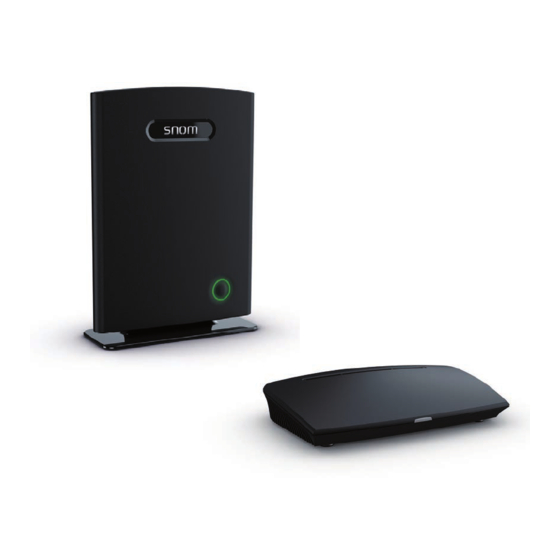
- Page 1 Admin and Installation Guide v1.02 Snom M700, Snom M300 Base stations...
-
Page 2: Table Of Contents
Opening the Web User Interface ........................25 Initial Settings ........................26 Servers ................................26 Language, Country, and Time/Date ......................26 Extensions - M700 ............................27 Setting up Extensions - M700 ......................27 Registering Handsets on M700 - Method 1 ................... 28 v1.02... - Page 3 Admin and Installation Guide M700, M300 Registering Handsets on M700 - Method 2 ................... 29 Selecting Emergency Alarm Setting on M700 ................30 Deregistering/Deleting Handsets and/or SIP Registrations on M700 ........31 Extensions - M300 ............................32 Setting up extension and handset on M300 .................. 32 Selecting Emergency Alarm Setting on M300 ................
-
Page 4: Copyright, Trademarks, Legal Disclaimers
All other product names and names of enterprises are the property of their respective owners. Product specifications are subject to change without notice. snom technology AG reserves the right to revise and change this document at any time, without being obliged to announce such revisions or changes beforehand or after the fact. -
Page 5: Important Information
Install the product at a minimum distance of 100 cm (39“) to persons and animals. ntended Use This product is designed for use with a snom M-series telephone. Any other use is considered unintended use. Any modification or reconstruction not described in the user manual is considered unintended use. -
Page 6: Additional Safety Information
Admin and Installation Guide M700, M300 Important Information • The operational temperature for the product is between -10°C and + 50°C (14°F and 122°F). • Do not install product in rooms with high humidity (for example, in bathrooms, laundry rooms, damp basements). - Page 7 Admin and Installation Guide M700, M300 Important Information Implanted medical devices Manufacturers of medical devices recommend that a minimum distance should be maintained between a wireless device and an implanted medical device, such as pacemakers or cardioverter defibrillators, to avoid potential interference with the medical device. Persons who have such devices should: •...
-
Page 8: Cleaning
Unauthorized opening, changing, or modifying the device will cause the warranty to lapse and may also result in the loss of CE conformity and the FCC certification. In case of malfunction contact authorized service personnel, your seller, or snom. The declarations of conformity can be requested from snom technology AG Wittestr. - Page 9 Admin and Installation Guide M700, M300 Important Information ◦ US: Ten Pao SMPS adapter, model no. S003GU050060, input 100-240 VAC, output 5V DC 600 mA, coaxial power connector ◦ AU: Ten Pao SMPS adapter, model no. S003GS050060, input 100-240 VAC, output 5V DC 600 mA, coaxial power connector v1.02...
-
Page 10: Additional Important Information Usa
• M700: T7HX8660 • M300: T7HX9430 Intended Use This device is designed for use with snom M-series phones. Any other use, modification or reconstruction of the product is considered unintended use. Important Safety Information Follow all instructions and warnings in the user manual, and on the equipment to prevent accidents. - Page 11 Admin and Installation Guide M700, M300 Important Information ◦ Equipment has been exposed to rain or water. ◦ Equipment does not work normally even when the operating instructions are followed. Adjust only those controls referred to in the operating instructions. Improper adjustment of other controls may result in damage and may require extensive work by an authorized service center.
-
Page 12: Fcc And Other Information
Admin and Installation Guide M700, M300 Important Information airways. Because of the inherent physical properties of radio waves, your communications can be received by radio receiving devices other than your own cordless telephone unit. Consequently, any communications using your cordless telephone may not be private. - Page 13 Bulletin 65 Supplement C (2001) and IEEE Std. 1528-2003 (December 2003). Standards Conformance This device is FCC certified and meets US health, safety, and environmental standards. The declaration of conformity can be requested from snom: snom technology AG Wittestr. 30G...
-
Page 14: Regulatory Information Canada
Admin and Installation Guide M700, M300 Introduction egulatory Information Canada IC Number: • M700: 4979B-X8660 • M300: 4979B-X9430 Interference information This device complies with Industry Canada licence-exempt RSS standard(s). Operation is subject to the following two conditions: (1) this device may not cause interference, and (2) this device must accept any interference, including interference that may cause undesired operation of the device. -
Page 15: Introduction
This admin guide covers the manual configuration of one base station. For information on multicell setup (M700 only), see "Multicell Deployment Guide snom 700". For information on provisioning settings, see "Provisioning Guide M700 and M300 Base Stations". -
Page 16: Setting Up
PoE injector, product number 00004065, as a mid-span device to provide power. Hardware Setup The M700 is delivered with the footstand attached and ready to be placed on a desktop, shelf, cabinet, or on the floor. Without the footstand, it can be hung on the wall or mounted under the ceiling. -
Page 17: Wall Or Ceiling Mounting
Setting Up Wall or Ceiling Mounting The M700 can be mounted under the ceiling or on the wall. Prior to mounting the device under the ceiling or on the wall, you must remove the footstand of the unit and connect the Ethernet cable to the RJ 45 jack on the back of the unit. - Page 18 Setting Up Wall mounting The M700 has two holes on the back (see Fig. 1 on page 16) that can be used to hang the unit on two screws or hooks on a wall. NOTE: Screws/hooks and wall anchors are not included in the delivery. Use screws and wall anchors suitable for your wall.
- Page 19 1. Bolt the ceiling plate to the ceiling with the four screw anchors and screws provided. 2. Pull off the footstand of the M700 (see Fig. 2 on page 17). 3. Plug the Ethernet cable into the jack on the back of the M700 and place it firmly into the cable guide.
-
Page 20: User Interface Of The Unit
Admin and Installation Guide M700, M300 Configuring User Interface of the Unit Status LED Fig. 6 LED Status Indicator At the front of the unit there is a multicolored LED for status signaling (Fig. 6). After the PoE cable - or the PoE injector cable, if PoE is not available - is connected to the unit, the orange LEDs will begin to blink, indicating that the unit is booting. -
Page 21: M300
Admin and Installation Guide M700, M300 Configuring Power is provided by the power adaptor included in the delivery. Hardware Setup The M300 can be placed on a desktop, a shelf, or any other flat, even surface or mounted on a wall. - Page 22 Admin and Installation Guide M700, M300 Configuring 1. Mark the centers of the two holes on the wall. The centers have to be 98 mm (3.86") apart horizontally (Fig. 2, above). Note: When the device is mounted on the wall, the connectors for the Ethernet cable and the power adapter are on what in this position is the bottom of the device (Fig.
-
Page 23: User Interface Of The Unit
Admin and Installation Guide M700, M300 Configuring User Interface of the Unit Status LED Status LED Fig. 1 Fig. 2 LED Status Indicator At the front or top of the unit, depending on whether the unit is standing on a flat surface or mounted on the wall, there is a multicolored LED for status signaling (Fig. -
Page 24: Configuring
VoIP service provider's PBX, and the handset(s) must be registered at the base station. This admin guide covers the manual configuration of the base station. For information on provisioning settings, see "Provisioning Guide M700 and M300 Base Stations". For information on multicell setup (M700 only), see "Multicell Deployment Guide snom 700". -
Page 25: Opening The Web User Interface
Admin and Installation Guide M700, M300 Configuring Opening the Web User Interface 1. Open a web browser on your PC. Enter the IP address, preceded by "http://" in the address bar (for example: http://192.168.10.115) and press ENTER. 2. Enter your user name and password in the pop-up window. The defaults for both are admin:... -
Page 26: Initial Settings
Admin and Installation Guide M700, M300 Configuring nitial Settings Servers During the initialization, the default server settings are loaded automatically. For a description of the settings, see "Servers" on page 55. Language, Country, and Time/Date The Country page contains drop-down menus for the selection of your country, a state or region within that country, if applicable, and the language to be used on the web interface of the base station. -
Page 27: Extensions - M700
To be able to use a handset, an extension must have been set up for it on the web interface of the base station, and the handset must be registered for the extension using one of two methods. On Snom corded desk phones, these extensions (or accounts) are called "identities". -
Page 28: Registering Handsets On M700 - Method 1
Central Directory Fig. 2 Registering Handsets on M700 - Method 1 1. After setting up the extension as shown in the preceding paragraph, click on the string of capital Fs underneath the IPEI header in the table on the Extensions page. -
Page 29: Registering Handsets On M700 - Method 2
For this method, you need to have all handsets within reach. Set up all extensions as described in "Setting up Extensions - M700" on page 27, then perform the following steps for each handset. 1. In the table on the Extensions page, check the box to the left of the Idx and then click on Register Handset(s). -
Page 30: Selecting Emergency Alarm Setting On M700
Admin and Installation Guide M700, M300 Central Directory 2. On the handset, select the Connectivity menu (Fig. 21). Fig. 10 Fig. 11 Fig. 12 Fig. 13 3. Select Register (Fig. 11). 4. M65/M85 y: Select the first field with the word Empty in it (Fig. 12). -
Page 31: Deregistering/Deleting Handsets And/Or Sip Registrations On M700
4. Select one of the configured profiles by clicking on its checkbox 5. Click on Save. Deregistering/Deleting Handsets and/or SIP Registrations on M700 Fig. 17 • To deregister a handset, click on the checkbox to the left of the Idx and on the link Deregister Handset(s). -
Page 32: Extensions - M300
Admin and Installation Guide M700, M300 Firmware Update Extensions - M300 To be able to use a handset, an extension must have been set up for it on the web interface of the base station, and the handset must be registered for the extension. - Page 33 Admin and Installation Guide M700, M300 Firmware Update Fig. 4 h. Click on Save. 2. On the Extensions page, click on the string of capital Fs underneath the IPEI header (Fig. 5). Fig. 5 3. Enter the IPEI of the handset (Fig. 7).
-
Page 34: Selecting Emergency Alarm Setting On M300
Admin and Installation Guide M700, M300 Firmware Update Fig. 8 Upon successful registration, the State of the Extension page should now be listed as SIP registered (Fig. 9). Fig. 9 Note: You also have to register the handset from the handset itself (Settings menu >... -
Page 35: Deleting Handset On M300
Admin and Installation Guide M700, M300 Firmware Update 4. Select one of the configured profiles by clicking on its checkbox (Fig. 10). 5. Click on Save. Deleting Handset on M300 1. Open the Handset page. 2. Click on the checkbox to the left of the Idx and on the link Delete Handset(s). -
Page 36: Registering M5 Repeaters
Admin and Installation Guide M700, M300 Firmware Update Registering M5 repeaters The maximum number of repeaters per base station is 3 (three). In a single-cell system, the base station (the DECT sync source) will always be RPN00; the repeaters will be numbered RPN01, RPN02, and RPN03. -
Page 37: Manual Registration
Admin and Installation Guide M700, M300 Firmware Update 6. Connect the repeater to a power outlet. 7. Press the reset tab on the back of the repeater for approx. 2 seconds until the LED blinks red briefly and then switches to double green flashes. - Page 38 Admin and Installation Guide M700, M300 Firmware Update Fig. 7 4. Select Manually from the DECT sync mode drop-down menu (Fig. 7). 5. Select the DECT sync source from the drop-down menu. In the example (Fig. 8, below), the DECT sync source of the second repeater is the first repeater from Fig.
- Page 39 Admin and Installation Guide M700, M300 Firmware Update Upon successful registration, the Repeater page will show the RPNs of the repeater and its DECT sync source and the state as "Enabled". Fig. 11 v1.02...
-
Page 40: Emergency Alarm
Alarm signal. The Call setting is mandatory. When the alarm button on the handset is pressed, the handset will call the phone number specified in the handset's Alarm settings (see "Selecting Emergency Alarm Setting on M700" on page 30 or "Selecting Emergency Alarm Setting on M300" on page 34, respectively). -
Page 41: Central Directory
Admin and Installation Guide M700, M300 Firmware Update entral Directory The central directory is accessible from all handsets registered at the same base station or in the same multicell installation. The central directory can be a phone list downloaded to the base station or an external source like the company LDAP register. - Page 42 Admin and Installation Guide M700, M300 Firmware Update • Number: A total of 21 characters. ◦ Valid characters: Digits 0 to 9 and the symbol +. You can use parentheses () around area codes and/or blank spaces to partition numbers into segments, but they will not be shown on the handset.
- Page 43 Admin and Installation Guide M700, M300 Firmware Update <IPPhoneDirectory> <DirectoryEntry> <Name></Name> <Telephone></Telephone> <Office></Office> <Mobile></Mobile> </DirectoryEntry> </IPPhoneDirectory> The indentations in the following example are only for demonstration purposes to set the individual entries apart. <IPPhoneDirectory> <DirectoryEntry> <Name>Name1</Name> <Telephone>phone number1</Telephone> <Office>office phone number1</Office>->...
-
Page 44: Downloading The Phone Directory File
Admin and Installation Guide M700, M300 Firmware Update Downloading the Phone Directory File 1. After preparing and saving the file as described in "Preparing the Phone Directory File", click on Browse (Fig. 1) and select the file on your PC or server (Fig. 2). The name of the file will appear to the right of the Browse button (Fig. -
Page 45: Ldap
Admin and Installation Guide M700, M300 Firmware Update On the Central Directory page, select LDAP from the drop-down menu of Location (see Fig. 1 on page 41) to open the LDAP server menu (Fig. 1, below). After saving your input, you may want to reboot the base station to make sure that the changes take effect. -
Page 46: Firmware Update
• The M700 can update up to 10, the M300 up to 5 wireless devices at a time. If more devices are registered with the base, they will be updated successively. Note: The base station randomly selects the devices for firmware transfer. It is not possible to assign priority to certain devices. -
Page 47: Using Snom's Update Server
The names of the firmware files also start with the capital M and are followed by one to three numerals, i.e., M700, M65, M5, etc. The product name is followed by the underscore _ which, in turn, is followed by a small v and the three-digit firmware version preceded by a zero, i.e., 0324, 0355, etc. -
Page 48: Downloading Update Files To Base Station And Transmitting To Wireless Devices
Admin and Installation Guide M700, M300 Firmware Update Downloading update files to base station and transmitting to wireless devices 1. Open the web user interface of the base station and click on Firmware Update in the menu on the left side. -
Page 49: Updating The Base Station
If the update was successful, the handset will turn on again, and the web interface will indicate the completion of the update and the current firmware version on the handset. rovisioning updates Please see the separate Provisioning Guide M700/M300 in our Wiki. v1.02... -
Page 50: Web Interface Settings
Admin and Installation Guide M700, M300 Firmware Update eb Interface Settings ome/Status The Home/Status page contains the summary of current operating condition and the settings of the base station and the handsets registered at the base station. It also contains the buttons for rebooting the base station. -
Page 51: Extensions
Admin and Installation Guide M700, M300 Firmware Update • MAC address: The media access control (MAC) address is a unique identifier assigned by the manufacturer. • IP address: The Internet Protocol address assigned by the network the base station is located in. -
Page 52: Add/Edit Extension
Admin and Installation Guide M700, M300 Firmware Update Setting Description Handset State Present, detached, located, removed, enabled,. Present@RPNxx: The handset is located at the base station with RPNxx (radio fixed part number). Detached: The handset is turned off. Located: The handset is configured to locate on a specific base station, but is unable to do so (e.g., the base station is turned off). - Page 53 Admin and Installation Guide M700, M300 Firmware Update Fig. 3 Parameter descriptions for Add extension and Edit Extension subpages: Setting Description Line name As required/desired. Specifies the line name for this extension on the handset. Used when user must select a line for outgoing calls.
-
Page 54: Handset (Mxx)
Admin and Installation Guide M700, M300 Firmware Update Setting Description Forwarding Unconditional Number On/off. All incoming calls for this extension will be forwarded to the number entered in the text field. Note: This setting (both the number and the enabled/disabled status) can be changed from the handset registered to the extension. -
Page 55: Servers
Admin and Installation Guide M700, M300 Firmware Update Setting Description This is the access code for registering the handset at the base station. The default is 0000 (four times zero). NOTE: This access code is not to be confused with either the PIN for resetting the handset to factory values or for deregistering it from the base station (default also 0000) or the PIN for accessing the mailbox. - Page 56 Admin and Installation Guide M700, M300 Firmware Update Setting Description NAT Adaptation Default: Disabled. Ensures that all SIP messages go directly to the NAT gateway. NOTE: Enabled: When the base station receives a SIP response to a REGISTER request with a “Via” header that includes the “received” parameter (e.g.: Via: SIP/2.0/UDP 10.1.1.1:4540;received=68.44.20.1), it will adapt its contact...
- Page 57 Admin and Installation Guide M700, M300 Firmware Update Setting Description Show extension on handset Default: Enabled. When enabled, the extensionnumber is displayed on the idle screen idle screen of the handset. Hold behavior Specifies the behaviour of the handset hold feature. The options are: RFC 3264: Hold is signaled according to RFC 3264, i.e.
- Page 58 Admin and Installation Guide M700, M300 Firmware Update Setting Description Codec priority This setting specifies the codec priority for audio compression and transmission. After changing the order of priority with the Up/Down buttons, click on Reset codes. NOTE: In a multicell setup, you must also go to the multicell page and click on Reboot chain in order to update the handsets in the multicell installation.
Need help?
Do you have a question about the M700 and is the answer not in the manual?
Questions and answers