Dell PowerVault MD3400 Owner's Manual
Storage arrays
Hide thumbs
Also See for PowerVault MD3400:
- Getting started manual (9 pages) ,
- Deployment manual (27 pages)

Related Manuals for Dell PowerVault MD3400


Summary of Contents for Dell PowerVault MD3400
- Page 1 Dell PowerVault MD3400 and MD3420 Storage Arrays Owner's Manual Regulatory Model: E03J and E04J Series Regulatory Type: E03J001 and E04J001...
- Page 2 WARNING: A WARNING indicates a potential for property damage, personal injury, or death. Copyright © 2014 Dell Inc. All rights reserved. This product is protected by U.S. and international copyright and intellectual property laws. Dell ™...
-
Page 3: Table Of Contents
Contents 1 About Your System....................7 ............................7 Introduction ....................7 Front-Panel Features and Indicators ....................10 Back-Panel Features and Indicators ....................... 10 Physical-Drive Indicator Patterns .................... 11 Power Supply and Cooling Fan Features ....................11 Power Indicator Codes and Features ........................12 Related Documentation 2 Controller Modules.................... - Page 4 ................... 23 Installing a RAID Controller Module Blank ..................23 Removing a RAID Controller Module .................... 24 Installing a RAID Controller Module ..................25 Opening the RAID Controller Module .................... 25 Closing the RAID Controller Module ...................26 RAID Controller Module Backup Battery Unit .............26 Removing the RAID Controller Module Backup Battery Unit ............26...
- Page 5 5 Technical Specifications..................43 6 Getting Help......................47 ..................... 47 Locating Your System Service Tag ........................... 47 Contacting Dell ........................47 Documentation Feedback...
-
Page 7: About Your System
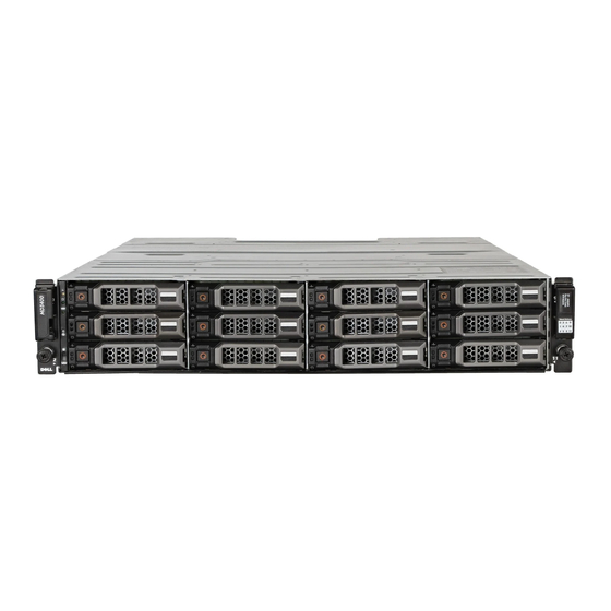
Its features support both single and dual RAID controller configurations. The Dell PowerVault MD3400 and MD 3420 Series storage array provides 12 Gbps SAS connectivity to the host server. It enables access for up to eight non-redundant servers or four redundant servers. - Page 8 Figure 2. Front-Panel Features and Indicators—Dell PowerVault MD3420 Figure 3. Front-Bezel Features and Indicators Item Indicator, Button, or Connector Description Enclosure status LED The enclosure status LED lights when the enclosure power is on. Lights blue during normal operation. Blinks blue when a host server is identifying the enclosure or when the system identification button is pressed.
- Page 9 Item Indicator, Button, or Connector Description Lights amber as enclosure boots or is reset. Blinks amber when the enclosure is either in a fault state or the hosts are not using the preferred path to a virtual disk. Power LED The power LED lights green when at least one power supply is supplying power to the enclosure.
-
Page 10: Back-Panel Features And Indicators
Back-Panel Features and Indicators Figure 4. Back-Panel Features and Indicators—Dell PowerVault MD3400 and MD3420 Series 600 W power supply/cooling fan RAID Controller Module 0 RAID Controller Module 1 600 W power supply/cooling fan Physical-Drive Indicator Patterns Figure 5. Physical-Drive Indicators... -
Page 11: Power Supply And Cooling Fan Features
Drive-Status Indicator Pattern Condition (RAID Only) Blinks green, amber, and turns Predicted drive failure Blinks amber four times per Drive failed second Blinks green slowly Drive rebuilding Steady green Drive online Blinks green three seconds, Rebuild aborted amber three seconds, and turns off six seconds Power Supply and Cooling Fan Features The MD3400 and MD3420 Series storage array includes two integrated, hot-swappable power supply/... -
Page 12: Related Documentation
Dell PowerVault MD Series Storage Arrays Administrator's Guide — Provides information about configuring and managing the system using the MDSM GUI. • Dell PowerVault Modular Disk Storage Arrays CLI Guide — Provides information about configuring and managing the system using the MDSM CLI. •... -
Page 13: Controller Modules
(simplex) and dual controller (duplex) modes, to connect the storage enclosure to hosts depending on specific redundancy needs. For information on cabling, see the MD3400 and MD3420 Series Storage Arrays Deployment Guide, at dell.com/powervaultmanuals. RAID Controller Module Connectors and Features Figure 7. MD3400 and MD3420 Series SAS RAID Controller Module... -
Page 14: Raid Controller Module-Additional Features
Item Component Function 12Gbps SAS IN port (2) Provides host-to-controller SAS connection. Seven segment display Displays status or error codes for the storage array. sequence Controller power LED Lights green when controller power is on. Turns off when controller is not powered. Controller fault LED Lights amber when controller fault is detected. -
Page 15: Storage Array Thermal Shutdown
Storage Array Thermal Shutdown The system automatically shuts down when system temperature exceeds the safe threshold. The battery backup unit protects against data loss by providing power to offload cache to non-volatile memory in the event of power loss. It is not necessary to shut down any MD1200 Series expansion enclosures attached to the storage array when thermal shutdown occurs. - Page 16 power failure is less likely to cause loss of data. The RAID controller automatically switches to write- through if cache mirroring is disabled, or if the battery is missing, or has a fault condition.
-
Page 17: Installing Array Components
Installing Array Components Recommended Tools You may need the following items to perform the procedures in this section: • Key to the system keylock • #2 Phillips screwdriver • Wrist grounding strap Front Bezel (Optional) Removing the Front Bezel Using the system key, unlock the front bezel (if locked). Lift the release latch next to the keylock. -
Page 18: Physical Drives
Secure the bezel with the keylock. Physical Drives SAFETY Models AMT E03J and E04J Models AMT, E03J, and E04J are intended for installation only in restricted access locations as defined in cl 1.2.7.3 of IEC 60950-1:2005. Depending on your configuration, your array either supports up to twenty-four 2.5-inch SAS physical drives or up to twelve 3.5-inch SAS physical drives in internal drive bays. -
Page 19: Installing A 3.5 Inch Physical-Drive Blank
Figure 10. Removing and Installing a 3.5 Inch Hard-Drive Blank (MD3400 only) physical-drive blank release button Installing a 3.5 Inch Physical-Drive Blank If installed, remove the front bezel. Insert the physical-drive blank into the physical-drive slot until the release button clicks into place. If applicable, install the front bezel. -
Page 20: Installing A Hot-Swap Physical Drive
Damage due to servicing that is not authorized by Dell is not covered by your warranty. Read and follow the safety instructions that came with the product. -
Page 21: Removing A Physical Drive From A Physical-Drive Carrier
Removing a Physical Drive From a Physical-Drive Carrier Remove the screws from the slide rails on the physical-drive carrier. Lift the physical drive out of the physical-drive carrier. Figure 12. Removing and Installing a Physical Drive Into a 2.5 inch Physical-Drive Carrier physical-drive carrier physical drive screws (4) -
Page 22: Installing A Physical Drive Into A Physical-Drive Carrier
Damage due to servicing that is not authorized by Dell is not covered by your warranty. Read and follow the safety instructions that came with the product. -
Page 23: Removing A Raid Controller Module Blank
Damage due to servicing that is not authorized by Dell is not covered by your warranty. Read and follow the safety instructions that came with the product. -
Page 24: Installing A Raid Controller Module
Damage due to servicing that is not authorized by Dell is not covered by your warranty. Read and follow the safety instructions that came with the product. -
Page 25: Opening The Raid Controller Module
Damage due to servicing that is not authorized by Dell is not covered by your warranty. Read and follow the safety instructions that came with the product. -
Page 26: Raid Controller Module Backup Battery Unit
Damage due to servicing that is not authorized by Dell is not covered by your warranty. Read and follow the safety instructions that came with the product. -
Page 27: Power Supply/Cooling Fan Module
Damage due to servicing that is not authorized by Dell is not covered by your warranty. Read and follow the safety instructions that came with the product. -
Page 28: Installing A Power Supply/Cooling Fan Module
Damage due to servicing that is not authorized by Dell is not covered by your warranty. Read and follow the safety instructions that came with the product. -
Page 29: Control Panel
Secure the power cable using the strap. Figure 19. Securing the Power Cable restraining strap CAUTION: When connecting the power cable, secure the cable with the strap. NOTE: If the array is powered on, all the power supply LEDs remain off until the AC power cable is connected to the power supply/cooling fan module and the power switch is turned on. -
Page 30: Installing The Control Panel
Slide the control panel out of the chassis after: – Pushing the release tab toward the front of the array in PowerVault MD3400. – Pulling the release pin toward the front of the array in PowerVault MD3420. Figure 20. Removing and Installing the Control Panel—PowerVault MD3400... -
Page 31: Backplane
Damage due to servicing that is not authorized by Dell is not covered by your warranty. Read and follow the safety instructions that came with the product. - Page 32 11. Remove the screws that secure the backplane and pull the backplane out of the array. Figure 22. Removing and Installing the RAID Controller Module/Power Supply Cage screws (6) RAID controller module/power supply cage Figure 23. Removing and Installing the Backplane—PowerVault MD3400 screws (5) backplane captive screw...
-
Page 33: Installing The Backplane
Figure 24. Removing and Installing the Backplane—PowerVault MD3420 screws (4) backplane captive screw Installing the Backplane Align the screw holes on the backplane with the screw holes on the array. Tighten the captive screw to secure the backplane to the chassis. Replace the screws that secure the backplane to the chassis. -
Page 35: Troubleshooting Your System
Damage due to servicing that is not authorized by Dell is not covered by your warranty. Read and follow the safety instructions that came with the product. -
Page 36: Troubleshooting Power Supply/Cooling Fan Modules
Damage due to servicing that is not authorized by Dell is not covered by your warranty. Read and follow the safety instructions that came with the product. -
Page 37: Troubleshooting Expansion Enclosure Management Modules
Damage due to servicing that is not authorized by Dell is not covered by your warranty. Read and follow the safety instructions that came with the product. -
Page 38: If The Array Status Led Is Solid Or Blinking Amber
Damage due to servicing that is not authorized by Dell is not covered by your warranty. Read and follow the safety instructions that came with the product. -
Page 39: Troubleshooting Array And Expansion Enclosure Connections
Damage due to servicing that is not authorized by Dell is not covered by your warranty. Read and follow the safety instructions that came with the product. -
Page 40: Troubleshooting A Damaged System
Damage due to servicing that is not authorized by Dell is not covered by your warranty. Read and follow the safety instructions that came with the product. -
Page 41: Noncritical Conditions
A physical disk in a redundant virtual disk has failed Invalid Storage Array The RAID controller module is supported only in a Dell-supported storage array. After installation in the storage array, the controller performs a set of validation checks. The array status LED is lit with a steady amber color while the RAID controller module completes these initial tests and the controllers are booted successfully. -
Page 43: Technical Specifications
4GB or 8GB of cache per controller Provides host-to-controller 12 Gbps SAS connection Expansion Modules Dell PowerVault MD1200 and MD1220 Each expansion enclosure holds Up to twelve 3.5 inch or expansion enclosures twenty-four 2.5 inch SAS, nearline SAS physical disks, or... - Page 44 1 °C/300 m (1 °F per 550 ft) above 900 m (2952.75 ft). NOTE: For information on supported expanded operating temperature range and configurations, see the Owner's Manual at dell.com/ powervaultmanuals. Storage –40 °C to 65 °C (–40 °F to 149 °F) with a maximum temperature gradation of 20 °C per hour...
- Page 45 Environmental Storage 5% to 95% at a maximum wet bulb temperature of 33 °C (91 °F) Maximum vibration Operating 0.26 G at 5 Hz to 350 Hz in operational orientation Storage 1.88 G at 10 Hz to 500 Hz for 15 minutes (all six sides tested) Maximum shock One shock pulse in the positive z axis of the system at...
-
Page 47: Getting Help
Select the appropriate service or support link based on your need. Documentation Feedback If you have feedback for this document, write to documentation_feedback@dell.com. Alternatively, you can click on the Feedback link in any of the Dell documentation pages, fill out the form, and click Submit to send your feedback.
Need help?
Do you have a question about the PowerVault MD3400 and is the answer not in the manual?
Questions and answers