Datalogic DS8100A Reference Manual
Hide thumbs
Also See for DS8100A:
- Reference manual (97 pages) ,
- Reference manual (141 pages) ,
- Reference manual (123 pages)
Table of Contents
Advertisement
Quick Links
Download this manual
See also:
Reference Manual
Advertisement
Table of Contents

Related Manuals for Datalogic DS8100A


Summary of Contents for Datalogic DS8100A
- Page 1 DS8100A Reference Manual...
- Page 3 DS8100A REFERENCE MANUAL...
- Page 4 ALL RIGHTS RESERVED Datalogic reserves the right to make modifications or improvements without prior notification. Datalogic shall not be liable for technical or editorial errors or omissions contained herein, nor for incidental or consequential damages resulting from the use of this material.
-
Page 5: Table Of Contents
CONTENTS REFERENCES ......................v Reference Documentation .................... v Services and Support ....................v SAFETY REGULATIONS ................... vi Electrical Safety ......................vi Laser Safety......................... vi Power Supply.......................vii WEEE Compliance ......................vii GENERAL VIEW ....................... viii GUIDE TO INSTALLATION ..................xi Point-to-Point Installation..................... xi Master/Slave Lonworks Installation ................xii INTRODUCTION ...................... - Page 6 Advanced Code Reconstruction (ACR™ 4)..............50 4.1.1 Tilt Angle for Advanced Code Reconstruction ............50 PackTrack™ .......................51 4.2.1 PackTrack™ Calibration for DS8100A ............... 53 4.2.2 PackTrack™ Calibration for DS8100A Oscillating Mirror Models ....... 55 Performance .......................55 4.3.1 Reading Conditions ....................55 Reading Diagrams ......................57 MAINTENANCE ......................
-
Page 7: References
Document about the Ethernet connectivity • Help On-Line in PDF format SERVICES AND SUPPORT Datalogic provides several services as well as technical support through its website. Log on to www.datalogic.com and click on the links indicated for further information including: • PRODUCTS Search through the links to arrive at your product page where you can download specific Manuals and Software &... -
Page 8: Safety Regulations
LASER SAFETY The following information is provided to comply with the rules imposed by international authorities and refers to the correct use of the DS8100A scanner. Standard Regulations This scanner utilizes up to 4 low-power laser diodes. Although staring directly at the laser beam momentarily causes no known biological damage, avoid staring at the beam as one would with any very strong light source, such as the sun. -
Page 9: Power Supply
Warning labels indicating exposure to laser light and the device classification are applied onto the body of the scanner (Figure A): DATALOGIC S.P.A. Via Candini, 2 AVOID EXPOSURE 40012 Calderara di Reno - Bologna - Italy Manufactured Volt LASER LIGHT IS EMITTED FROM THIS APERTURE Model No. -
Page 10: General View
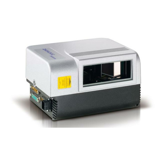
GENERAL VIEW DS8100A Figure A - DS8100A Laser Beam Output Window Connector Panel Display Laser Safety Label Product Label Service Access Cap Warning and Device Class Label Mounting Holes viii... - Page 11 DS8100A Figure B - DS8100A Oscillating Mirror Version Laser Beam Output Window Laser Safety Label Figure C – Display and Keypad Panel Programming Keypad TX Data LED (Green) Network LED (Red) Power On LED (Green) Phase On LED (Yellow) LCD Display...
- Page 12 Figure D – Connector Panel for Standard Models Lonworks 17-pin male connector Serial interface and I/O 26-pin connector Lonworks 17-pin female connector Figure E – Connector Panel for Ethernet Models Lonworks 17-pin male connector Serial interface and I/O 26-pin connector Lonworks 17-pin female connector Harting RJ industrial connector...
-
Page 13: Guide To Installation
2.5 and par. 4.4. 3) Make electrical connections to your DS8100A scanner by: a) Connecting the DS8100A scanner to the C-BOX 100 by means of one of the CAB-601X cables provided as accessory (see par. 1.5). -
Page 14: Master/Slave Lonworks Installation
2.5 and par. 4.4. 3) Make electrical connections to your DS8100A scanner by: a) Connecting the DS8100A Master scanner to the C-BOX 100 by means of one of the CAB-601X cables provided as accessory (see par. 1.5). - Page 15 8) Optionally, perform the ASR Network Configuration procedure for system backup purposes (see par. 5.2.1). 9) Exit the configuration program and run your application. The installation is now complete. xiii...
-
Page 17: Introduction
1 INTRODUCTION 1.1 PRODUCT DESCRIPTION The DS8100A scanner is a barcode reader complete with decoder designed to provide an innovative and high performance solution in omnidirectional reading applications by combining the following advanced technologies with Datalogic solid experience in the material handling sector. - Page 18 • Flexibility The high frequency laser diode modulation system guarantees complete immunity to ambient light and allows installation of the DS8100A in any working area. Reading parcels on conveyors • As a result of the ASTRA™ multiple laser technology, DS8100A gives a great real time DOF even on high speed conveyors.
-
Page 19: Model Description
Oscillating mirror models are used when coverage of a large reading area is required, mainly in picket fence applications. The oscillating mirror is placed in front of the reading aperture of the DS8100A scanner to deflect the laser beam. As the mirror moves, this sweeping function of the laser beam allows the coverage of a larger area to locate the barcodes. -
Page 20: Indicators
TX DATA (green) Indicates data transmission both on the main and on the auxiliary interface. NETWORK (red) Indicates the Lonworks network is functioning correctly. This LED is normally ON. * These LEDs are always OFF when the DS8100A works as Slave. -
Page 21: Accessories
INTRODUCTION 1.5 ACCESSORIES The following accessories are available on request for DS8100A: Name Description Part Number PWR-120 J-box power unit 110/230 VAC 24 V 120 W 93ACC1530 PWR-240 J-box power unit 110/230 VAC 24 V 240 W 93ACC1070 PWR-480 J-box power unit 110/230 VAC 24 V 480 W... -
Page 22: Installation
DS8100A reader to other devices in the system (i.e. C-BOX 100 etc.). NOTE 2.1 PACKAGE CONTENTS Verify that the DS8100A reader and all the parts supplied with the equipment are present and intact when opening the packaging; the list of parts includes: •... -
Page 23: Mechanical Mounting
2.2 MECHANICAL MOUNTING 2.2.1 Mounting the Scanner DS8100A can be installed to operate in any position. There are 16 screw holes (M6 X 8) on the sides of the scanner for mounting. The diagram below can be used for installation; refer to par. -
Page 24: Mounting The Scanner With Accessories
[2.66] inch Figure 5 - DS8100A Oscillating Mirror Model Overall Dimensions 2.2.2 Mounting the Scanner with Accessories The following accessories allow installing the DS8100A reader in the most suitable position for your network layout: ST-163 mounting bracket; FBK-8100 fast bracket. - Page 25 INSTALLATION The FBK-8100 is a fast bracket kit allowing quick and easy mounting of the scanner on the ST-163 bracket. It is particularly useful when performing a scanner automatic replacement (see par. 5.2), since the scanner can be simply substituted with a new one while maintaining its physical position within the network.
-
Page 26: Electrical Connections
RJ45 Industrial modular connector The table below gives the pinout of the C-BOX 100 terminal block connectors. Use this pinout when the DS8100A reader is connected in a network by means of the C-BOX 100: C-BOX 100 Terminal Block Connectors... -
Page 27: Main/Aux. Serial Interface And I/O Connector
INSTALLATION 2.3.1 Main/Aux. Serial Interface and I/O Connector The DS8100A Standard and Fieldbus models are equipped with a 26-pin male D-sub connector for connection to the host computer, power supply and input/output signals. The details of the connector pins are indicated in the following table:... -
Page 28: Main Interface
The RTS and CTS signals control data transmission and synchronize the connected devices. If the RTS/CTS hardware protocol is enabled, the DS8100A activates the RTS output to indicate a message can be transmitted. The receiving unit must activate the CTS input to enable the transmission. - Page 29 Figure 11 - RS485 Full-Duplex Interface Connections RS485 Half-Duplex Interface The RS485 half-duplex interface can be used for multidrop connections with a Datalogic multiplexer or it can also be used for a master/slave layout. The overall maximum cable length should not exceed 1200 m (3937 ft).
-
Page 30: Auxiliary Interface
Earth Ground Figure 13 - RS232 Auxiliary Interface Connections Inputs The inputs of the reader are on the 26-pin connector of the DS8100A. These inputs are called EXT_TRIG, IN2, IN3 and IN4. Name Function EXT_TRIG A External trigger (polarity insensitive) - Page 31 5 ms or 500 µ s. In particular, EXT_TRIG, IN3 and IN4 share the same value which usually corresponds to 5 ms when using a photoelectric sensor, while IN2 has a different value which is set to 500 µ s when this input is used for the Encoder. DS8100A Vext EXTERNAL TRIGGER/ENCODER...
- Page 32 DS8100A Vext DS8100A EXTERNAL DEVICE IN3A + 5V Ground Vext IN4A + 5V INREF Ground Figure 18 - IN3/IN4 PNP Input Command using External Power DS8100A EXTERNAL DEVICE INREF + 5V IN3A Ground EXTERNAL DEVICE + 5V IN4A Ground Figure 19 - IN3/IN4 NPN Input Command using Scanner Power Input devices can be supplied by either scanner power (VS and GND) or external power supplies (Vext).
-
Page 33: Outputs
The limit requested by the maximum power dissipation is more important than that of the maximum collector current: if one of these outputs is continuously driven, the maximum current must not be more than 40 mA although 130 mA may be reached in pulse conditions. DS8100A USER INTERFACE Vext 30 Vdc max Figure 20 –... -
Page 34: Lonworks Input/Output Connector
DS8100A The OUT3 electrical features are given below: Maximum voltage ± 100 V Collector current (pulse) 240 mA Max. Collector current (continuous) 150 mA Max. R on 6 – 15 Ω R off > 500 Ω Off-state leakage current < 1 µA Maximum power dissipation 550 mW at 50°C (Ambient temperature). -
Page 35: Network Termination
CAB-8605 is a power and Lonworks termination cable to be used for connecting the DS8100A master to an external power unit within the network; while CAB-8305 is a power and bus return cable to be used for connecting the last DS8100A slave to an external power unit. -
Page 36: Lonworks Interface
The Lonworks network is used for both input and output connection to build a multi-sided or omni-station system connecting several readers. The DS8100A master usually employs the 17-pin female connector for output connection to the first slave, while the 17-pin male connector is terminated by inserting the BTK8102 terminator (see Figure 23 for details). - Page 37 LON B- REF_I/O = male connector = female connector Figure 27 – DS8100A Master Termination The diagram below represents the Lonworks bus return of a DS8100A working as slave by means of the BTK-8100 terminator. Slave BTK-8100 LON A+ LON A-...
-
Page 38: Ethernet Connector
DS8100A 2.3.3 Ethernet Connector This connector is only available for DS8100A Ethernet models and allows the Ethernet connection between the host and the reader. Figure 29 – Harting RJ Industrial® Push Pull Male Connector Figure 30 – DS8100A Harting RJ Industrial® Female Connector This interface and the connector pinout (see the following table) are IEEE 802.3 10 BaseT... -
Page 39: Ethernet Interface
The supply voltage for correct operation of the scanner must be between 20 and 30 VDC. The max. power consumption is 30 W including startup current. Several accessory power supplies are available to power the DS8100A(s) and reading station components. See par. 1.5. -
Page 40: User Interface
Test Cable for DS8100A 2.5 POSITIONING THE SCANNER The DS8100A scanner is able to decode barcode labels at a variety of angles, however significant angular distortion may degrade reading performance. When mounting the DS8100A take into consideration these three ideal label position angles: Pitch 0°, Skew 0°... -
Page 41: Typical Layouts
Figure 35 – "Tilt" angle 2.6 TYPICAL LAYOUTS The DS8100A scanners can be connected in a variety of layouts depending on the number of scanners used and the required complexity of the reading station. These layouts range from Single Stand Alone to Complex Lonworks Networks. -
Page 42: Point-To-Point
In this case no External Trigger is used and the C-BOX 100 only supplies the reader. The DS8100A (Ethernet model) is connected to a fieldbus remote Host. It can be activated by a signal generated by the remote Host or always be active if working in Automatic operating mode. -
Page 43: Pass Through
INSTALLATION 2.6.2 Pass Through When Pass Through is activated on the Auxiliary interface, the DS8100A reader can be integrated in a network consisting of different scanners not provided with a Lonworks interface. This connection mode allows two or more devices to be connected to a single external serial interface. -
Page 44: Rs232 Master/Slave
Figure 39 – Pass Through Connection for Fieldbus Models 2.6.3 RS232 Master/Slave The RS232 master/slave connection is used to integrate a DS8100A reader in a network consisting of different scanners not provided with a Lonworks interface. The Slave scanners use RS232 only on the main and auxiliary interfaces. Each slave scanner transmits the messages received by the auxiliary interface onto the main interface. - Page 45 C-BOX 100 DS4600A Slave 2 PWR-120 C-BOX 100 P.S. (Presence Sensor) connected to External Trigger input. Auxiliary Serial Interface Main Serial Interface Figure 40 – RS232 Master/Slave for DS8100A Standard Models Remote PLC DS8100A Fieldbus Master Network CAB601X C-BOX 100...
-
Page 46: Multiplexer
DS8100A 2.6.4 Multiplexer The Multiplexer connection is used to integrate a DS8100A slave reader in a Multidrop network consisting of different scanners not provided with a Lonworks interface. Each scanner connected Multiplexer (MX4000) with RS485 half-duplex main interface. P.S.* P.S.* P.S.*... -
Page 47: Local Lonworks Network
INSTALLATION 2.6.5 Local Lonworks Network A local Lonworks network allows logically connecting a DS8100A master reader with up to 31 DS8100A slaves. Actually, the maximum number of readers to be employed in the network depends on the system operating conditions, that is adopted operating mode and amount of data stream. -
Page 48: Small Synchronized Network
DS8100A Small Synchronized Network When building a small local Lonworks network (less than 10 scanners), the DS8100A master reader must be connected to a local host computer or a C-BOX 100 by means of a cable connected to the 26-pin D-sub male connector. - Page 49 INSTALLATION The following image shows a system consisting of five readers where the external signals (trigger, encoder, serial to host, etc.) are connected to the master through the C-BOX 100. The system is powered by the PWR-240 where: • the master is connected through CAB-860X, which also provides bus termination •...
-
Page 50: Large Synchronized Network
PS Aux CAB-810x CAB-810x CAB-810x up to 3 scanners BTK8100 branch Bus Return DX8200A DX8200A DX8200A CAB-810X CAB-810x CAB-810x up to 4 scanners per branch DS8100A DS8100A DS8100A DS8100A Figure 45 – Large Synchronized Network with DX8200A and DS8100A Scanners... -
Page 51: Multidata Network
Figure 46 – Large Synchronized Network Reading Station Multidata Network In this layout, one master and up to 7 DS8100A slave readers have their own P.S. and therefore multiple reading phases. Each P.S. is connected through a C-BOX 100, which in turn is connected to its relative scanner through a CAB-601X cable. -
Page 52: Fieldbus Network
2.6.6 Fieldbus Network The Fieldbus (Ethernet) model offers connectivity without any converter or adapter needed. The DS8100A master Fieldbus communicates with a remote host (for ex. remote PC connected via Internet) by means of a cable connected to the Fieldbus (Ethernet) connector provided. -
Page 53: Keypad And Display
INSTALLATION KEYPAD AND DISPLAY The DS8100A keypad allows entering a menu for selection of one of the following functions: • Welcome: shows the current software release and operating mode; • Autolearn: starts the procedure making it possible to obtain an automatic, accurate and fast configuration of DS8100A without the necessity of directly checking/modifying the relevant parameters;... -
Page 54: Software Configuration
DS8100A 3 SOFTWARE CONFIGURATION 3.1 GENIUS™ INSTALLATION ™ Genius is a new Datalogic scanner configuration tool providing several important advantages: • Wizard approach for low skilled users; • Multi-language version; • Defined configuration directly stored in the reader; • Communication protocol independent from the physical interface allowing to consider the reader as a remote object to be configured and monitored. -
Page 55: Test Operating Mode
Sending the configuration to the scanner. Figure 50 - Genius™ Wizard Closing Window Test Operating Mode This operating mode is not available when DS8100A works as slave. NOTE Figure 51 - Test Mode Selection This operating mode causes the reader to be continuously activated allowing to verify its reading features and its reading position with respect to the barcode. -
Page 56: On Line Operating Mode
This operating mode causes the reader to be connected to an external Presence Sensor using EXT TRIG+ and EXT TRIG- inputs. During the active phase of the presence sensor, the DS8100A reader tries to acquire and correctly decode the code. -
Page 57: Genius™ Network Setup Through Master
SOFTWARE CONFIGURATION 3.2.2 Genius™ Network Setup Through Master The Network Setup allows configuring your Local Lonworks Network through the Master using Genius™. Three different procedures are available to define the number of network slave scanners, their label and address according to two main conditions: Condition Available Procedure Feature... - Page 58 DS8100A The following dialog box appears asking whether to send the configuration to the Master or not: 2. Click the "Yes" button, then click on the icon available on the Toolbar to make the “Devices” area appear next to the Parameter Explorer window. By repeatedly clicking the icon this area will be displayed or hidden.
-
Page 59: Net-Autoset
SOFTWARE CONFIGURATION 3. Then, proceed with the network setup by using one of the icons available on the Tool Bar according to the procedure to follow: Net-Autoset procedure Network Wizard procedure Express Network Setup procedure Net-Autoset This procedure is to be used when all scanner addresses and labels are unknown (typically when configuring the network for the first time or whenever a network reconfiguration is required). -
Page 60: Network Wizard
DS8100A Network Wizard Before performing this procedure, a Lonworks address must be assigned to each slave scanner. The most practical method is through the Net-Autoset procedure. See par. 3.2.3 for alternative address assignment methods. Once all addresses have been assigned, the Network Wizard is to be used when one or more scanner addresses and labels need to be modified. - Page 61 SOFTWARE CONFIGURATION 2. If desired, select a slave scanner within the "Current Devices" area and click on the icon (or select the "Show Device" option from the right-click menu) to make the dialog box appear as follows: The "Show Device" option is particularly useful after the Net-Autoset procedure or whenever it is necessary to know which address is assigned to a specific slave scanner.
-
Page 62: Alternative Slave Address Assignment
DS8100A 3.2.3 Alternative Slave Address Assignment As alternatives to Network Setup through the Master, each Slave scanner can be assigned an address through the following methods: • address setting through the Local Device Network Settings item in the Device Menu with the slave scanner connected to Genius™... -
Page 63: Parameter Default Values
SOFTWARE CONFIGURATION 3.4 PARAMETER DEFAULT VALUES The following table contains the list of the factory default settings for the DS8100A. Genius™ also allows checking the parameter default values by selecting the "Compare parameters" option available in the Tools menu and comparing the current scanner configuration to the default one. - Page 64 DS8100A Parameter Default Setting Reading Parameters Scan Line Amplitude Amplitude Settings Enable Disabled (unchecked) Data Communication Settings Host Application Protocol Type Standard Data Format Header TX Start With data Termination After No Read Message Enabled (checked) Message Tx Trigger Selection...
- Page 65 SOFTWARE CONFIGURATION Parameter Default Setting Output 1 Line State Normally Open Activation Event Complete Read Alternative Activation Event Wrong Deactivation Event Timeout Alternative Deactivation Event None Deactivation Timeout (ms) Output 2 Line State Normally Open Activation Event No Read Alternative Activation Event Partial Read Deactivation Event Timeout...
-
Page 66: Reading Features
With just a set of partial scans on the label (obtained using the motion of the label itself), the DS8100A is able to “reconstruct” the barcode. A typical set of partial scans is shown in the figure below: Code Direction Figure 58 –... -
Page 67: Packtrack
4.3.1, depending on standard α values of 45° and 30°. 4.2 PACKTRACK™ PackTrack™ is a patented operating mode for Datalogic Omni-Directional Reading Stations used to read and correctly assign codes read on different packs when placed in the scanner Reading Area at the same time. - Page 68 DS8100A All PackTrack™ functionalities are programmed via the Genius™ tool (refer to the Genius™ Help On-Line for details). For correct functioning, the PackTrack™ operating mode requires a calibration just after the installation of the scanners. This operation is absolutely necessary to make the scanner recognize its position in space.
-
Page 69: Packtrack™ Calibration For Ds8100A
READING FEATURES 4.2.1 PackTrack™ Calibration for DS8100A By means of the Genius™ software tool SPY, the user can perform PackTrack™ calibration. Select the “SPY” option from the Tools menu or click on the related icon on the Genius™ toolbar to open the following dialog box: Note: When selecting a slave scanner through the Master, click on the slave to calibrate in the Devices window, then click the SPY icon. - Page 70 DS8100A By selecting the “PackTrack Calibration” option a further dialog box appears allowing to start calibration: Position 1 Position 2 Position 3 Figure 65 – Performing the PackTrack™ Calibration 1. Place the code at the desired position on the scan line (i.e. Position 1) 2.
-
Page 71: Packtrack™ Calibration For Ds8100A Oscillating Mirror Models
READING FEATURES 4.2.2 PackTrack™ Calibration for DS8100A Oscillating Mirror Models The DS8100A oscillating mirror models can be used in PackTrack™ operating mode only when the scanner is mounted so that the scan line is parallel to the conveyor direction as... - Page 72 DS8100A Minimum Code Height for ACR Reading (mm) 45° 30° Conveyor Speed (m/s) 0.25 0.30 Code 39 0.33 Code Resolution 0.38 (mm) 0.50 0.72 1.00 Ratio 3:1; Interdigit = Module Size Table 2 Minimum Code Height for ACR Reading (mm) 45°...
-
Page 73: Reading Diagrams
READING FEATURES 4.4 READING DIAGRAMS DS8100A-3X00 (0.50 mm/20 mils) The diagram shows an average reading area obtained considering different barcode types of variable quality. (in) (cm) -700 (cm) (in) Note: (0,0) is the center of the laser beam output window. - Page 74 DS8100A DS8100A-3X10 (0.38 mm/15 mils) The diagram shows an average reading area obtained considering different barcode types of variable quality. (in) (cm) (cm) (in) Note: (0,0) is the center of the laser beam output window. CONDITIONS Code = Interleaved 2/5 or Code 39 = 0.90...
- Page 75 READING FEATURES DS8100A-3X20 (0.30 mm/12 mils) The diagram shows an average reading area obtained considering different barcode types of variable quality. (in) (cm) (in) (cm) Note: (0,0) is the center of the laser beam output window. CONDITIONS Code = Interleaved 2/5 or Code 39 = 0.90...
- Page 76 DS8100A DS8100A-3X30 (0.25 mm/10 mils) The diagram shows an average reading area obtained considering different barcode types of variable quality. (in) (cm) (cm) (in) Note: (0,0) is the center of the laser beam output window. CONDITIONS Code = Interleaved 2/5 or Code 39 = 0.90...
- Page 77 READING FEATURES DS8100A-3X05 (0.50 mm/20 mils) The diagram shows an average reading area obtained considering different barcode types of variable quality. (in) (cm) -700 (cm) (in) Note: (0,0) is the center of the laser beam output window. CONDITIONS Code = Interleaved 2/5 or Code 39 = 0.90...
- Page 78 DS8100A DS8100A-3X15 (0.38 mm/15 mils) The diagram shows an average reading area obtained considering different barcode types of variable quality. (in) (cm) (cm) (in) Note: (0,0) is the center of the laser beam output window. CONDITIONS Code = Interleaved 2/5 or Code 39 = 0.90...
- Page 79 READING FEATURES DS8100A-3X25 (0.30 mm/12 mils) The diagram shows an average reading area obtained considering different barcode types of variable quality. (in) (cm) (cm) (in) Note: (0,0) is the center of the laser beam output window. CONDITIONS Code = Interleaved 2/5 or Code 39 = 0.90...
- Page 80 DS8100A DS8100A-3X35 (0.25 mm/10 mils) The diagram shows an average reading area obtained considering different barcode types of variable quality. (in) (cm) (cm) (in) Note: (0,0) is the center of the laser beam output window. CONDITIONS Code = Interleaved 2/5 or Code 39 = 0.90...
-
Page 81: Maintenance
Repeat the operation frequently in particularly dirty environments. Use soft material and alcohol to clean the window and avoid any abrasive substances. Clean the window of the DS8100A when the scanner is turned off or at least when the laser beam is not active. -
Page 82: Scanner Replacement Procedure
DS8100A 5.2.2 Scanner Replacement Procedure The ASR procedure requires replacing one scanner at a time. NOTE Slave 1. Power down the entire system. 2. Replace the Slave scanner with a new one (default settings). 3. Power up the system and wait for initialization. -
Page 83: Troubleshooting
TROUBLESHOOTING 6 TROUBLESHOOTING Before contacting your local Datalogic office or Datalogic Partner or ARC, it is suggested to save the device configuration to a *.ddc file by means of the Genius™ software configuration program and check the device exact model and serial number. - Page 84 DS8100A TROUBLESHOOTING GUIDE Problem Suggestion On Line Mode and Serial On Line • Genius™ software configuration Mode: program select the OPERATING MODES folder and check the “Reading Phase the reader does not respond correctly to Timeout” parameterization. the expected external signal end.
- Page 85 Suggestion Communication: • If the LED is OFF, check the connections between the DS8100A slaves and the SC6000 the scanner “Network” LED is not lit. or DS8100A master. If the error persists, contact your Datalogic distributor. How do I obtain my units’ serial •...
-
Page 86: Technical Features
DS8100A 7 TECHNICAL FEATURES ELECTRICAL FEATURES (see note 1) Supply voltage 20 to 30 Vdc Power consumption 20 W typical 30 W Max. (including startup current) Main Baud Rate Common Communication Interfaces RS232 RS485 full-duplex 1200 to 115200 RS485 half-duplex 20 mA C.L. - Page 87 TECHNICAL FEATURES SOFTWARE FEATURES Readable Codes Interleaved 2/5 Code 39 Standard Codabar Code 128 EAN 128 Code 93 (standard and full ASCII) EAN/UPC (including Add-on 2 and Add-on 5) Code selection Up to 10 codes during one reading phase Headers and Terminators Up to 128-byte headers and 128-byte terminators Operating modes On Line, Serial On Line, Automatic, Test,...
-
Page 88: Glossary
This organization (a service of the Food and Drug Administration) is responsible for the safety regulations governing acceptable limitations on electronic radiation from laser devices. Datalogic devices are in compliance with the CDRH regulations. CD SQUARE™ CD SQUARE™ provides useful information on label position and object shape elaborated during the barcode reading phase. - Page 89 (LCD). LEDs have extremely long lifetimes when properly operated. Multidrop Line A single communications circuit that interconnects many stations, each of which contains terminal devices. See RS485. PACKTRACK™ PackTrack™ is a Datalogic patented parcel tracking system which improves the reading features omnidirectional stations. particular, PackTrack™...
- Page 90 Scanner A device that examines a printed pattern (barcode) and either passes the uninterpreted data to a decoder or decodes the data and passes it onto the Host system. Serial Port An I/O port used to connect a scanner to your computer. Signal An impulse or fluctuating electrical quantity (i.e.: a voltage or current) the variations of which represent changes in information.
-
Page 91: Index
INDEX Accessories; 5 Network Setup; 41 ACR™ 4; 50 Network Termination; 19 Cleaning; 65 Operating Mode Connectors Automatic; 40 26-pin connector; 11 On Line; 40 Ethernet; 22 Test; 39 Outputs; 17 Default Values; 47 Package Contents; 6 PackTrack™; 51 Electrical Connections; 10 Parameter Explorer Window;... - Page 92 Gerät bescheinigt, daß das Gerät declare que el declare que el DS8100A-XXXX DS8100A-XXXX, Laser Scanner e tutti i suoi modelli and all its models et tous ses modèles und seine modelle y todos sus modelos...
Need help?
Do you have a question about the DS8100A and is the answer not in the manual?
Questions and answers