
Related Manuals for King Canada KC-108N


Summary of Contents for King Canada KC-108N
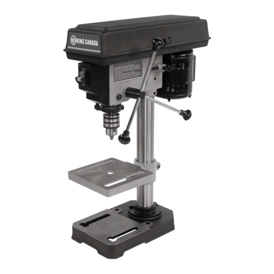
- Page 1 8” BENCH DRILL PRESS 10/2015 INSTRUCTION MANUAL MODEL: KC-108N COPYRIGHT © 2015 ALL RIGHTS RESERVED BY KING CANADA TOOLS INC.
-
Page 2: Warranty Information
King Canada service center. Contact your retailer or visit our web site at www.kingcanada.com for an updated listing of our authorized service centers. In cooperation with our authorized serviced center, King Canada will either repair or replace the product if any part or parts covered under this warranty which examination proves to be defective in workmanship or material during the warranty period. -
Page 3: General Safety Instructions For Power Tools
GENERAL SAFETY INSTRUCTIONS FOR POWER TOOLS 1. KNOW YOUR TOOL footwear is recommended. Wear protective hair covering to con- tain long hair. Roll up long sleeves above the elbows. Read and understand the owners manual and labels affixed to the 12. -
Page 4: Electrical Information
ELECTRICAL INFORMATION WARNING ALL ELECTRICAL CONNECTIONS MUST BE DONE BY A QUALIFIED ELECTRICIAN. FAILURE TO COMPLY MAY RESULT IN SERIOUS INJURY! ALL ADJUSTMENTS OR REPAIRS MUST BE DONE WITH THE MACHINE DISCONNECTED FROM THE POWER SOURCE. FAILURE TO COMPLY MAY RESULT IN SERIOUS INJURY! POWER SUPPLY USING ON/OFF SWITCH WITH REMOVABLE SAFETY KEY WARNING: YOUR DRILL PRESS MUST BE CONNECTED TO A 120V... -
Page 5: Electrical Diagram
ELECTRICAL DIAGRAM & SPECIFICATIONS FIGURE 3 MODEL ....................................KC-108N VOLTAGE ......................................120V HP........................................1/3HP AMPS ......................................2.5A MOTOR R.P.M....................................1750 Hz ........................................60 PHASE ........................................1 CHUCK CAPACITY ..................................1/2” SWING ........................................8” MAX. SPINDLE TRAVEL..................................2” MAX. DISTANCE FROM CHUCK TO THE TABLE ..........................7” MAX. DISTANCE FROM CHUCK TO THE BASE..........................10”... -
Page 6: Getting To Know Your Drill Press
GETTING TO KNOW YOUR DRILL PRESS 8. SPRING CAP 1. BELT GUARD 9. DEPTH POINTER 2. BELT TENSION 19. SWITCH KNOB 3. HEAD LOCK SET SCREWS 15. FEED HANDLES 16. CHUCK 4. TABLE SUPPORT 10. DEPTH SCALE 14. TABLE 18. STOP NUTS 17. -
Page 7: Assembly Instructions
ASSEMBLY INSTRUCTIONS BASE AND COLUMN ASSEMBLY (FIG.6) Table/Support assembly 1. Position the base on the floor. Remove the protective covering and dis- card. 2. Remove protective sleeve from the column and discard. Place the col- umn assembly on the base, align the holes in the column support with Column the holes in the base. - Page 8 ASSEMBLY INSTRUCTIONS INSTALLING THE FEED HANDLES (FIG.10) 1. Locate the three feed handles among the loose parts. 2. Screw the feed handle tightly into the threaded holes in the hub. Feed handle FIGURE 10 INSTALLING THE BELT GUARD KNOB 1. To attach the belt guard knob, use the knob and a pan head screw from Belt guard knob the loose parts bag.
- Page 9 ADJUSTMENTS WARNING! For your own safety, turn the switch OFF and remove the plug from Spring cap the power source before making any adjustements. To avoid injury from thrown parts due to the spring release, follow instructions carefully and wear safety Notch glasses.
-
Page 10: Operation
OPERATION FEEDING Pull down the feed handles with only enough effort to allow the drill to cut. Feeding too slowly might cause the drill to burn...feeding too rapidly might stop the motor...cause the belt or drill to slip... tear the workpiece loose or break the drill bit. -
Page 11: Maintenance & Troubleshooting
MAINTENANCE / TROUBLESHOOTING LUBRICATION All of the ball bearings are packed with grease at the factory. They require no further lubrication. Periodically lubricate the splines (Grooves) in the spindle and the rack (Teeth of the quill). WARNING! For your own safety, tur n the switch “OFF” and remove the plug from the power source before maintaining or lubricating your drill press.
Need help?
Do you have a question about the KC-108N and is the answer not in the manual?
Questions and answers