Table of Contents
Advertisement
Quick Links
Download this manual
See also:
Operating Manual
Advertisement
Table of Contents

Related Manuals for junger D02


Summary of Contents for junger D02
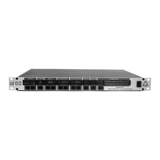
- Page 1 DIGITAL DYNAMICS PROCESSOR OPERATIONS MANUAL rev. 3.1 Justus-von-Liebig-Straße 7, 12489 Berlin, Germany Telefon: (030) 67 77 21 - 0 Fax: (030) 67 77 21 – 46 www.junger-audio.com...
- Page 2 INTRODUCTION The digital dynamics processor model d 02 is a professional studio device that processes the dynamic range of digital , as well as analog audio signals. unit comes with digital AES/EBU Interface and high resolution 24 Bit A/D Converters, that allows dynamic range processing (compressor, limiter, expander) in the digital and analog domain.
-
Page 3: Table Of Contents
CONTENTS The design of the device ..........1.1. Basic functions ............1.2. The Jünger Audio dynamics processor principle ..1.3. A/D-conversion with digital full scale level ....Installation ................. 2.1. Power supply .............. 2.2. Connections ..............2.3. Switches for configuration of the unit ......2.4. -
Page 4: The Design Of The Device
THE DESIGN OF THE DEVICE The d 02 digital dynamics processor can be used to process 1.1. both digital and analog audio signals. The device is primarily Basic designed for use with stereo signals. Functions Digital input signals can be connected in the AES/EBU standard format, including SP/DIF and OPTICAL formats. -
Page 5: The Jünger Audio Dynamics Processor Principle
1. THE DESIGN OF THE DEVICE A change in the dynamic range of an audio signal is a non-linear 1.2. process. The gain of a dynamic range processor is not constant as it is with the gain of a linear amplifier. The gain varies in time Jünger Audio depending on the input signal and depending on the specific Dynamics... - Page 6 1. THE DESIGN OF THE DEVICE inaudible processing - and they are very easy to use. The Jünger Audio dynamics processors work according to a multi-loop principle Multi-loop principle, operating with an interaction between several frequency linear control circuits. The resulting attack and release times of this system are variable and adapted to the evolution of the input signal.
- Page 7 1. THE DESIGN OF THE DEVICE Figure 1 shows the basic principles of dynamic range processors. The compression of the programme signal takes place evenly over the entire range and not only at the upper end above a certain threshold level. Dynamic structures of the input signal (e.g.
- Page 8 1. THE DESIGN OF THE DEVICE fig.. 2: static characteristics: compressor static output level d02 (dBFS) characteristics: compressor 2.0 : 1 1.6 : 1 1.3 : 1 1.1 : 1 input level (dBFS) compression gain: max. 10 dB parameter: ratio static characteristics: compressor fig.
-
Page 9: A/D-Conversion With Digital Full Scale Level
1. THE DESIGN OF THE DEVICE The usable dynamic range for digital recording is determined at 1.3. the top by the highest possible digital signal (full scale) and at the A/D- bottom by the lowest possible digital resolution. This range Conversion with cannot be fully exploited when using a conventional analog-... -
Page 10: Installation
INSTALLATION 2.1. The digital dynamics processor d02 is a device under the safety category Schutzklasse 1 in keeping with the VDE 0804 Power Supply standards and may only used with power supply installations built according to regulations. Check the voltage details printed at the rear panel are the same as your local mains electricity supply. -
Page 11: Switches For Configuration Of The Unit
(Sometimes it is helpful to change the channel status, f.i. if following units don’t want to accept incoming signals.) If using digital input of d02 unit is transparent for channel status information. There is no changing or modification of it possible. - Page 12 The analog input gain of the d02 should be set so that the maximum possible studio output level which will occur in practice must not overload the A/D converter.
-
Page 13: Control And Display Elements
CONTROL AND DISPLAY ELEMENTS All functions of the digital dynamics processor d 02 are activated by buttons. The front panel shows easily recognizable function groups. input By pressing the left button in the input section the required input signal can be selected. Each time the button is pressed the input selection is changed and one of the three LED's above the button lights to show the newly selected input. - Page 14 3. CONTROL AND DISPLAY ELEMENTS Press the PRESET button to select the one of the four operating preset programs of the unit which best corresponds to the kind of audio programme material which is being processed. Each operating program has optimum values of dynamic control characteristics (such as attack and release times etc.) for a different type of programme material.
- Page 15 3. CONTROL AND DISPLAY ELEMENTS The expander THRESHOLD can be changed upward or downward with two expander buttons and is visible on the LEDs above them. Four expander thresholds (-60 dB, -50 dB, -40 dB, -30 dB) can be selected. The threshold level is related to the choosed digital reference level.
- Page 16 3. CONTROL AND DISPLAY ELEMENTS limiter The limiter limits the maximum output signal level of the d02 precisely to the set digital reference level. (see also 2.4., and, for details of setting the digital reference level, see under "display"). The limiter should be always active to ensure that output level of the d02 never exceeds the preset digital reference level.
- Page 17 3. CONTROL AND DISPLAY ELEMENTS The two channel LED display has three display modes (input level, output display level and gain change). Press the button in the display section to change the display mode. The selected display mode is indicated by the lighting of the appropriate LED above the display button and to the left of the display meters.
- Page 18 3. CONTROL AND DISPLAY ELEMENTS The DISPLAY button has a second function in addtion to changing the Setup selections display mode. It is used for setting the internal digital reference level, which is using display key the maximum output level which the limiter will allow to be output by the unit. Hold down the display button continuously for a few seconds and the unit will enter internal digital reference level setting mode.
-
Page 19: Functional Description
"sampling frequency" LED's in the input section of the d02 front panel will flash red. Digital audio input signals in the standard AES/EBU format pass from the AES/EBU input connector through a transformer (as specified by the AES/EBU standard) to the AES/EBU interface circuitry. - Page 20 48KHz) selected with the button in the input section and is displayed by the lighting of a green LED in the d02's front panel sampling frequency display. For applications where analog input is used, but where the AES/EBU digital output of the unit must be...
- Page 21 AES/EBU or Word Clock signal (and hence the operating sampling frequency of the d02) will be indicated by the lighting of a yellow LED in the d02's front panel sampling frequency display. three LED's in the d02's front panel sampling frequency...
- Page 22 4. FUNCTIONAL DESCRIPTION The lower the signal level, the higher the gain of the compressor will be. Independently of compression ratio, the maximum amount of compression gain can be adjusted so that inadmissible increase of background noises (e.g. live atmos, air- conditioning, hum and noise) may occur during signal pauses.
- Page 23 4. FUNCTIONAL DESCRIPTION If the internal digital reference level is reduced to below 0dBFs then the maximum analog output level will be correspondingly reduced by the action of the limiter. For example if the internal digital reference level is reduced to -9dBFs (9dB below the maximum possible level that can be represented digitally) then the actual maximum digital level that will be received by the D/A converter will be 9dB below...
-
Page 24: Application Notes
APPLICATION NOTES possible choose one of eight different control 5.1. characteristics for the dynamics processor. Each of the four Presets different sets of control characteristics provides ideal dynamics control for a different type of programme signal as follows: stereo mode 2-channel-mode 1 - universal 5 - universal... -
Page 25: Working With Headroom
5. APPLICATION NOTES If such a signal is compressed or limited in a dynamics processor, problems will occur as the peak levels for high frequencies do not represent the true values. The dynamics processor causes a change in peak levels which would, however, lead to a change in the treble content after passing through the external deemphasis filter. -
Page 26: Influence Of Signal Delay Time
5. APPLICATION NOTES fig. 5: static characteristics: compressor Static output level d02 (dBFS) characteristics: Compressor/ Limiter with -9dBFS Headroom 9 dB Digital Reference 2.0 : 1 Level 1.6 : 1 1.3 : 1 1.1. : 1 input level (dBFS) compression gain: max. 10 dB... -
Page 27: Selection Of Parameters To Increase Loudness
5. APPLICATION NOTES Signal compression and the loudness enhancement of the digital 5.5. audio signal resulting from it can be achieved by combining two Selection of dynamic range control processes: firstly, the compression parameters to achieved by increasing small and medium signal levels and increase loudness secondly, linear amplification combined with the inaudible limitation of individual, remaining peak levels with the limiter. - Page 28 5. APPLICATION NOTES In order to receive a better quality during cut down the data to 16 redithering bit one must redithering the material with corresponding devices. Here the device is calculating random numbers (dither signal) and add a different random number to every sample. Then it will be cut off to 16 bit.
-
Page 29: Applications
APPLICATIONS - mastering of CD, DCC, MD maximum recording level without clipping increased programme density and loudness - digital recording and mixing increased loudness level (compressor, limiter) eliminating noise signals (expander) - FM-Broadcast, TV-Sound signal conditioning matching dynamic range of different programme signals increasing signal loudness level - limiter for digital or analog transmission links always digital full scale signal, without clipping... -
Page 30: Technical Specification
TECHNICAL SPECIFICATION sample rate : 30 kHz ... 50 kHz digital audio data format : 24-bit (AES/EBU) input / output 24-bit (A/D-,D/A-converter) AES/EBU level : 5 Vpp / 110 Ohm, balanced connector : input format : AES professional, AES consumer output format : same as input S/PDIF... -
Page 31: Warranty And Service Information
WARRANTY AND SERVICE INFORMATION JÜNGER AUDIO grants a two-year warranty on the digital dynamics processor MODEL d02 If the unit has to be serviced, please send it, ideally in the original box, to: JÜNGER AUDIO - Studiotechnik GmbH Justus-von-Liebig-Str. 7... - Page 32 KONFORMITÄTSERKLÄRUNG DECLARATION OF CONFORMITY Geräteart: Digital Filter Processor Type of equipment: digital filter processor model d02 Produkt / Product Das bezeichnete Produkt stimmt mit den Vorschriften folgender EU-Richtlinie(n) überein: The aforementioned product complies with the following Europaen Council Directive(s): 89/336/EWG (geändert durch 91/263/EWG und 92/31/EWG)
Need help?
Do you have a question about the D02 and is the answer not in the manual?
Questions and answers