Table of Contents
Advertisement
READ AND SAVE THESE INSTRUCTIONS
Thank you for purchasing this Panasonic product.
Please read these instructions carefully before attempting to install, operate or service
the Panasonic product. Failure to comply with instructions could result in personal injury
or property damage. Please explain to users how to operate and maintain the product
after installation, and this booklet should be presented to users.
Please retain this booklet for future reference.
INSTALLATION INSTRUCTIONS
Model No.
Contents
DESCRIPTION
UNPACKING
MAINTENANCE (CLEANING)
PRODUCT SERVICE
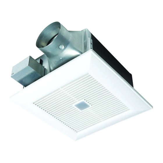
Ventilating Fan
BACK COVER
2-3
4
4
4
5
6
6
7-8
9
10
11
11
Advertisement
Table of Contents


Need help?
Do you have a question about the FV-08-11VFM5 and is the answer not in the manual?
Questions and answers