
Related Manuals for Schick Handel DT596/ID


Summary of Contents for Schick Handel DT596/ID
- Page 1 2 -Wire Intercom System DT596(F)/ID User Manual RF CARD RF CARD DT596/ID DT596F/ID DT-ENG-596(F)ID-V1 110S923...
-
Page 2: Parts And Functions
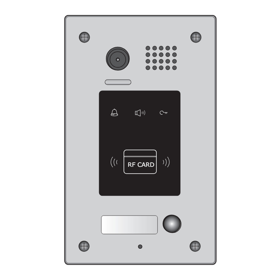
Camera Lens Speaker Indicator ID card window RF CARD RF CARD 28 mm Nameplate Call Button Microphone Rainy Cover DT596/ID 90 mm Camera Lens Speaker Indicator ID card window RF CARD RF CARD Nameplate Call Button Screws for panel mounting... -
Page 3: Door Station Mounting
• • S1+,•S2+:•Lock•power(+)•output,•to•connect•2•locks. • • S-:•Lock•power(-)•output,•connect•to•the•power(-)•input•of•locks(only•when•using•the•camera•to•power• the•locks,•if•using•the•external•power•supply•for•the•locks,•the•S-•will•not•be•connected). 3.Door Station Mounting DT596/ID Mounting adjust camera angle Drill holes in the wall to match the size of Connect the cable correctly and adjust screws and attach the rainy cover to the wall. -
Page 4: Adjusting Camera Angle
DT596F/ID Mounting adjust camera angle Drill a hole in the wall to match the size of the Connect the cable correctly and adjust mounting box and attach to the wall. right angle for camera Attach the panel to the mounting box and Place name label use screws supplied to fix the panel Adjusting Camera Angle... -
Page 5: Placing Name Label
Placing Name Label Press•the•plastic•cover•on•right/left•side•to•move•away•the•cover,insert•a•name•paper,then•put•the•plastic• cover•back•to•the•panel. RF CARD 4. System Wiring and Electric Lock Connection Basic Connection monitor L1 L2 PL S1+ S2+ S-... -
Page 6: Electric Lock Connection
Electric Lock Connection Door Lock Controlled with Internal Power •••••Note: 1.• Electronic•lock•of•Power-on-to-unlock•type•should•be•used. 2.• The•door•lock•is•limited•to•12V,•and•holding•current•must•be•less•than•250mA. 3.• The•door•lock•control•is•not•timed•from•Exit•Button(EB). 4.• The•Unlock Mode•Parameter•of•Monitor•must•be•set•to•0•(by•default). 1 2 3 1 2 3 Connect one lock Connect two locks Jumper position in Jumper position in LOCK LOCK LOCK Door Lock Controlled with Dry Contact •••••Note: 1.•... -
Page 7: Unlock Parameter Setting(Set On Monitor)
connect•one•lock connect•two•locks Take off the Jumper Take off the Jumper POWER POWER SUPPLY SUPPLY LOCK LOCK LOCK Unlock parameter setting(set on monitor) H/W : DT14-CT a1.3 S/W: V17.11.418.00 Manual Monitor Intercom Multimedia Monitor Local addr: Unlock timing: Video standard: Close UI-CODE: Memory Album... -
Page 8: Multi Door Stations Connection
Multi Door Stations Connection monitors DBC4 A B C D 85~260VAC 4# Camera 3# Camera 2# Camera 1# Camera ID=11 ID=01 ID=10 ID=00 1 2 3 4 1 2 3 4 1 2 3 4 1 2 3 4 L1 L2 PL S1+ S2+ S- L1 L2 PL S1+ S2+ S- L1 L2 PL S1+ S2+ S- L1 L2 PL S1+ S2+ S-... -
Page 9: Multi Monitors Connection
Multi Monitors Connection Basic IN-OUT Wiring Mode monitor 3 4 5 6 Code=15, DIP-6=on monitor 3 4 5 6 Code=14, DIP-6=off monitor 3 4 5 6 Code=0, DIP-6=off 85~260AC ID=00 RF CARD 1 2 3 4... -
Page 10: Dip Switches Settings Of Door Station
5.DIP Switches Setting ON(1) OFF(0) DIP Switches Settings of Door Station Total•4•bits•on•the•DIP•switches•can•be•configured.The•switches•can•be•modified•either•before•or•after• installation. Setting Item Bit state Descriptions Default•setting,•ID•=•0(00),•set•to•the•first•Door•Station. 1 2 34 ID•=•1(10),•set•to•the•second•Door•Station. Bit1•and•Bit2 1 2 34 (it•is•used•to•set•the•ID• code•for•door•station) ID•=•2(01),•set•to•the•third•Door•Station. 1 2 34 ID•=•3(11),•set•to•the•fourth•Door•Station. 1 2 34 The•relay•2•doesn't•respond•the•second•lock,showing•user• cards•controlled•two•locks•or•pressing•unlock•2nd•on•monitor• can• not• release• the• second• lock.During• this• time,After• continuously•showing•access•card•10•times,the•relay•2•will•be•... -
Page 11: Id Card Registration
Bit-6•is•used•to•match•the•video•impendance,•which•have•to•be•set•to•on•if•the•monitor•is•in•the•end•of•the• bus,•otherwise•set•to•off.• Bit state Setting Bit state Setting The•monitor• The•monitor•is•• is•at•the•end• not•at•the•end• of•the•bus. 1 2 3 4 5 1 2 3 4 5 of•the•bus. Bit-1•to•Bit-5•are•used•to•User•Code•setting.The•DT596(F)/ID•responds•to•0~15•. Bit state User Code Bit state User Code Bit state User Code Code=0 Code=6 Code=11 3 4 5 3 4 5 3 4 5... -
Page 12: Add User Cards
Add User Cards: 1.Control one lock(the first lock) Show•the• Show•user•cards•to•be• Show•the•• MASTER CARD MASTER CARD •card•to•ID•card•window• added,•one•by•one.• ••card•to•exit.But•it•will• in•standby•mode. return•to•standby•mode•if•no• operation•within•15s. blue blue blue (on) (off) (blink) (off) (off) (off) beep+,beep beep+ beep,beep+ 2.Control two locks Show•the• Press•"CALL"•button. Show•the•• MASTER CARD MASTER CARD •card•to•ID•card•window•... -
Page 13: Unlock Operations
Authorize master cards: By•default,there•are•two•master•cards•marked• •and• •,but•you• MASTER CARD ADD MASTER CARD DELETE should•know•that•the•master•card•can•be•authorized•by•users•at•any•time.That•means•any•two•user•cards• can•be•authorized•to•master•cards,When•registered•new•master•cards,•the•old•master•cards•are•invalid• automatically. Continuously•set•DIP4• The•first•card•showed•is•the• The•second•card•showed•is• switch•status•to•"off"->"on"• •card,it the• • MASTER CARD ADD MASTER CARD DELETE ->"off">"on"->off"->"on"•in• will•return•to•standby•if•no• card,it•will•return•to•standby• sequence,must•finish•in•3s. operation•within•10s. if•no•operation•within•10s. blue blue blue (on) (on) (off) (on) beep+ beep+,beep... -
Page 14: Specifications
• • • Pinhole•Sharp•Color•CCD;•420•TV•Lines; • • Lock•Power•supply:•• • • 12Vdc,•300mA(Internal•Power); • • Number•of•relay•circuits:•• • • • • Mounting:• • • •••••••••••••••••Surface•mounting(DT596/ID)•••••••••••••••••••••••••••••••••• ••••••••••••••••••••••••••••••••••••••••••••••••••••••••••••Flush•mounting•(DT596F/ID)••••••••••••••• • • Working•temperature:• • • •-10ºC•~•+45ºC • • Wiring:• • • • 2•wires,non-polarity • • Dimension:• • •... -
Page 15: Cables Requirements
10. Cables Requirements The•maximum•distance•of•the•wiring•is•limited•in•the•DT•system.•Using•different•cables•may•also•affect•the• maximum•distance•which•the•system•can•reach.• The farest monitor monitor with two or four monitors monitor monitor DBC/DBC-4 When Monitor quantity < 20 Cable Usage 60• 60• 30• Twisted•cable•2x0.75•mm 80• 80• 40• Twisted•cable•2x1•mm When Monitor quantity > 20 Cable Usage 70• 30•... - Page 16 The design and specifications can be modified without notice to the user. Right to interpret and copyright of this manual are reserved. DT-ENG-596(F)/ID-V1 110S926...
- Page 17 Anleitung für DT27/25/692SD/TD7 Videostationen ManualDT69SD/TDXXSerie-DE/Schick2010...
- Page 18 Vorsichtsmassnahmen/Fehler : Bitte schützen Sie Ihre Anlage vor Erschütterungen Bitte reinigen Sie alle Komponenten mit einen Bauwolltuch (keine Chemikalien) Es kann zu Bildverzerrungen kommen wenn andere elektrische Geräte zu nah sind Bitte schützen Sie alle Geräte vor Feuchtigkeit zu hohen Temperaturen und Staub Befestigen Sie den Monitor in einer Höhe von ca.
- Page 19 Innenmonitor Teile und Funktionen Bedienanleitung Betätigen Sie den Bildschirm oder drücken Sie den Menü Knopf (Sensortaster unten rechts) , der Bildschirm öffnet sich und es wird der Kalender angezeigt Datum Wochentage und die Uhrzeit .Betätigen Sie den Bildschirm erneut und es erscheint das Hauptmenü...
- Page 20 Intercom : Bei dieser Funktion erreichen Sie das Interkom- Menü • Interkom by Namlist : Hier werden alle Namen im Haus wenn programmiert angezeigt (nicht mit Jeder Türstation möglich) sind einzeln anwählbar Inner Call : hier können alle Slave - Stationen in einer Wohnung angewählt werden (Je nach Türstation 4 oder max.
- Page 21 Bildspeicher Wiedergabe und Einstellung Memory Playback: Anzeigen • der gespeicherten Bilder (immer 4 Stück) Verfügbare Funktionen löschen, vor/zurück , alles löschen, ins Hauptmenü Bilder können manual während • des Gesprächs aufgenommen werden oder ja nach Einstellung werden 1-4-8 Bilder aller 1,5 Sekunden aufgenommen Das erste Bild wird nach Aufbau der Verbindung nach 3 s erstell...
- Page 22 Experten Einstellung : Über die Betätigung des Unteren Icon About werden die Systemdaten Ihres Monitors angezeigt . Berühren Sie den Bildschirm für 2 Sekunden und sie kommen in das Menü Installations Einstelllungen Achtung: Ihr Monitor ist für den Masterbetrieb bereits eingerichtet. Es müssen für eine Standart Verbindung keine Veränderungen im Menü...
- Page 23 • Stromverbrauch : DC 24V (supplied by Adaptor) • Stromversorgung der Türstation (Türöffner): 12Vdc, 300mA(Internal Power) • Verbrauch im Standby Standby 0.5W,Working status 15W(for kits) • Abmessungf Monitor 7 Inch color TFT-LCD • Display Auflösung : 800*3(RGB)*480 pixels • Video Signal: 1Vp-p,75 ,CCIR standard •...
- Page 24 Gefahrhinweise Achtung: Arbeiten am 230V Stromnetz dürfen nur von Fachleuten durchgeführt werden bitte beauftragen Sie einen Elektrofachmann mit dem Anschluss des Hustschienennetzadapters . Es besteht Lebensgefahr ! Beachten Sie bitte: Entsorgen sie das Produkt am Ende seiner Lebensdauer, gemäß den geltenden gesetzlichen Vorschriften. Sie können das Produkt an jeder Kommunalen Sammelstelle für Altgeräte unentgeltlich zur Umwelt und Fachgerechten abgeben .
Need help?
Do you have a question about the DT596/ID and is the answer not in the manual?
Questions and answers