EverFocus EPN4122i Quick Installation Manual
Epn series
Hide thumbs
Also See for EPN4122i:
- User manual (112 pages) ,
- User manual (100 pages) ,
- User manual (110 pages)
Table of Contents
Advertisement
Quick Links
Download this manual
See also:
User Manual
Advertisement
Table of Contents

Related Manuals for EverFocus EPN4122i


Summary of Contents for EverFocus EPN4122i
-
Page 1: Quick Installation Guide
EPN Series IP Speed Dome Quick Installation Guide Copyright © EverFocus Electronics Corp, Release Date: April, 2013 ... -
Page 2: System Requirement
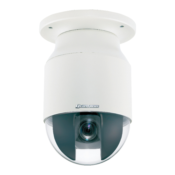
EPN Series 1. Overview The EPN series IP Speed Dome comes in two types: Indoor (EPN4122i / 4220i) and Outdoor (EPN4122 / 4220). No. Item Name No. Item Name No. Item Name 1 Top Housing 2 Outer Housing 3 Camera Main Body Packing List The main box contains 3 large boxes and a small box. Each box contains the items as listed below. Please check that there is no missing item in the package before installing. Box 1: Top housing with a network connector and tool packet Tool packet (Indoor only): Includes 6 Plastic Anchors and 6 Screws. Box 2: Camera main body with a tool packet Tool packet: Includes 1 pair of Gloves, 3 Desiccant Packs and 1 Power Terminal Block. Box 3: Outer housing Small Box: Power adapter Software CD Quick Installation Guide ... -
Page 3: Cable Descriptions
EPN Series 3. Cables and I/O Terminal Block Cable Descriptions No Name and Descriptions No Name and Descriptions 1 RS‐485+ (Yellow): Connects to an RS‐485 device. 5 Audio In: Connects to a microphone. 2 RS‐485‐ (Orange): Connects to an RS‐485 device. 6 Audio Out: Connects to a speaker. 3 24 VAC~: Connects to the power adapter. 7 RJ‐45 Cable: Connects to the network. 4 Test‐Out Cable: Connects to a DVR or monitor. Note: Microphones with external power supplies are required. I/O Terminal Block The I/O terminal block, located on the rear panel of the Base Board, can be used to develop applications for alarm input and output, motion detection, PTZ control or a variety of other functions. Pin Assignment ... -
Page 4: Optional Accessories
EPN Series 4. Optional Accessories EPTZ‐PBOX (External power connection box) Corner mount adapter Pole mount adapter Indoor ceiling pendant mount bracket Outdoor sunshield Indoor recessed mount bracket Wall mount bracket Indoor concrete ceiling mount adapter EKB500 (RS‐485 keyboard) EKB200 (USB controller keyboard) ... - Page 5 EPN Series To replace the desiccant bags: 1. On the Top Housing, slightly press the black plastic socket backward and lift up the base board. 2. Remove the desiccant bags from the top housing. 3. Stick the supplied 3 new desiccant bags inside the top housing. Place back the base board. Note: Ensure Not to place the desiccant bags under the position of the fan. To insert a micro SD card: 1. Unscrew the four screws on the camera main body to remove the black housing. 2. Insert the micro SD card to the card slot. Screw back the black housing. ...
- Page 6 EPN Series Installing Outdoor Models (EPN4122 / 4220) Two mounting types are available for the outdoor models: Wall Mount and Ceiling Mount. Wall Mount 1. Drill 4 screw‐depth holes for the bracket base plate and then drill a through‐wall hole for the camera cables. You can optionally drill a second through‐wall hole to separate cable feeding (see Step 4). 2. Attach the waterproof silicon pad to the bracket base plate for waterproofing. Waterproof Bracket base plate silicon pad 3. Feed the camera’s cables through the conduit in the wall mount bracket. 4. Connect the camera’s cables to the related devices. Feed the cables of the related devices, such as the speaker, through the wall and then through the holes of the bracket base plate. 5. Screw the bracket base to the wall using the 4 screws. 6. Screw the wall mount bracket to the bracket base using the 4 long screws. 7. Put on the supplied gloves. Line up the red triangles and then push the main body upward to the top housing. Push the main body upward into the top housing until the orange catches on both sides click into position. ...
- Page 7 EPN Series Ceiling Mount It is required to use the optional Indoor Recessed Mount Bracket and Surface Ring to attach the camera to the ceiling. 1. Cut a hole on the ceiling using the supplied template. 2. Slightly turn the surface ring and remove it from the bracket. 3. Place and then screw the camera’s top housing on the top disk of the bracket using the 3 short screws. 4. Use a cable or other mechanism to hang the bracket on the ceiling. Screw the 3 rotation clips of the bracket on the ceiling using a screwdriver. 5. Put on the supplied gloves and then push the main body upward to the top housing. See Step 7 in Wall Mount. 6. Screw the housing cover to the top housing slowly by twisting it clockwise. 7. Slide the surface ring to the fillister on the bracket. Note: When you turn on the power, the camera will enter self‐inspection mode and run a self‐testing program. Once this is complete, you will be able to operate it via any IP network. ...
-
Page 8: Network Connections
EPN Series 6. Network Connections You can use one of the methods below to connect the camera to the network. Router or LAN connection This is the most common connection in which the IP camera is connected to a router and allows multiple users on and off site to see the IP camera on a LAN/WAN (Internet). The camera must be assigned an IP address that is compatible with its LAN. By setting up port forwarding on the router, you can view cameras from outside of the LAN via the Internet. To remotely access the Web interface of the IP camera, please refer to 7.3.2 DDNS in the User’s Manual. To set up port forwarding, please consult the manual of the router. Straight‐through LAN patch cable ... - Page 9 EPN Series Direct High‐Speed Connection In a Direct High‐Speed Connection, the camera connects directly to a modem without the need for a router. You need to set the static or dynamic WAN IP address assigned by your ISP (Internet Service Provider) in the camera’s configuration web pages. To access the camera, just type “http://xxx”, where xxx is the IP address given by your ISP. If you have a dynamic IP address, this connection may require that you use DDNS for a reliable connection. Please refer to 7.3.2 DDNS in the User’s Manual. One‐to‐one Connection (Directly from PC to IP Camera) You can connect directly without using a switch, router or modem. However, only the PC connected to the camera will be able to view the IP camera. You will also have to manually assign a compatible IP address to both the computer and the IP camera. Unless the PC has another network connection, the IP camera will be the only network device visible to the PC. See the diagram below: ...
-
Page 10: Checking The Dynamic Ip Address
EPN Series 7. Checking the Dynamic IP Address You can look up the IP address and access the Web interface of the camera using the IP Utility (IPU) software, which is included in the software CD. 1. Install and then start the IPU program . The following dialog box appears. 2. IPU will automatically search the cameras connected in the LAN. The default network values of the cameras will be displayed. By default, the network protocol of the camera is DHCP. 3. To configure the network settings, select a camera and then click Login/Multi Login to log in. 4. Type the user ID and password. Click OK. Note: 1. The default user ID is user1 and the default password is 11111111. 2. If you select more than one camera that has the same user ID / password, you will be able to log in several cameras at once. ... - Page 11 EPN Series 5. To change the IP settings, double‐click the values in the column and type the numbers or select an option. Click Set IP Address to save the settings. Note: Most networks support DHCP protocol, but if you are unsure of your network protocol, please consult your IP administrator for network configuration details. 6. To access the camera, highlight the camera and click Connect to Selected IP. The Internet Explorer window pops up. 7. Type the user ID and password to log in. The Live View window of the camera appears. Note: 1. You might be required to download ActiveX for viewing the camera feed. If asked, click Yes. 2. To enable Remove Live View, Firmware Upgrade and ActiveX Prompt on Internet Explorer, some settings have to be complete. Please refer to 4.2 Settings for Microsoft Internet Explorer in the User’s Manual. ...
-
Page 12: Upgrading Firmware
EPN Series 8. Upgrading Firmware You can upgrade camera’s firmware using the IP Utility software, which is included in the software CD. 1. Follow Step 1 to Step 4 in 7. Checking the Dynamic IP Address to log in the camera. 2. Check the box to select the camera and then click Upgrade Firmware. A browsing window appears. 3. Select the firmware file (.evb) and then click Open. The IP Utility will automatically upgrade the firmware. The camera will reboot once the update is complete. Click Find Devices, the new firmware version should be displayed in the last part of the Machine Name. ... - Page 13 Bandra Kurla Complex, Bandra (East), Mumbai 400051, India TEL: +91 22 6128 8700 FAX: +91 22 6128 8705 www.everfocus.in sales@everfocus.in Ihr EverFocus Produkt wurde entwickelt Your EverFocus product is designed und hergestellt mit qualitativ and manufactured with high quality hochwertigen Materialien und materials and components which can Komponenten, die recycelt und wieder be recycled and reused.
Need help?
Do you have a question about the EPN4122i and is the answer not in the manual?
Questions and answers