Table of Contents
Advertisement
Available languages
Available languages
SAVE THIS MANUAL FOR FUTURE REFERENCE
Your brad nailer has been engineered and manufactured to
our high standard for dependability, ease of operation, and
operator safety. When properly cared for, it will give you
years of rugged, trouble-free performance.
WARNING:
To reduce the risk of injury, the user
must read and understand the operator's manual before
using this product.
Thank you for your purchase.
GUARDE ESTE MANUAL PARA FUTURAS CONSULTAS
OPERATOR'S MANUAL
MANUAL DEL OPERADOR
18 GAUGE BRAD NAILER
CALIBRE 18, CLAVADORA DE PUNTILLAS
Su clavadora de puntillas ha sido diseñada y fabricada de
conformidad con nuestras estrictas normas para brindar
fiabilidad, facilidad de uso y seguridad para el operador.
Con el debido cuidado, le brindará muchos años de sólido
y eficiente funcionamiento.
ADVERTENCIA
lesiones, el usuario debe leer y comprender el manual
del operador antes de usar este producto..
Le agradecemos su compra.
H200BND
: Para reducir el riesgo de
Advertisement
Table of Contents

Related Manuals for Husky H200BND


Summary of Contents for Husky H200BND
- Page 1 OPERATOR’S MANUAL MANUAL DEL OPERADOR 18 GAUGE BRAD NAILER CALIBRE 18, CLAVADORA DE PUNTILLAS H200BND SAVE THIS MANUAL FOR FUTURE REFERENCE Su clavadora de puntillas ha sido diseñada y fabricada de Your brad nailer has been engineered and manufactured to...
-
Page 2: Table Of Contents
TABLE OF CONTENTS / INDICE DE CONTENIDO Introduction..................................2 Introducción General Safety Rules ...............................3 Reglas de seguridad generales Specific Safety Rules ..............................4-5 Reglas de seguridad específicas Symbols ...................................6 Símbolos Glossary of Terms ................................7 Glosario de términos Features ...................................8 Características Assembly ..................................8... -
Page 3: General Safety Rules
GENERAL SAFETy RULES Do not overreach. Keep proper footing and balance DANGER: at all times. Proper footing and balance enables better control of the tool in unexpected situations. READ AND UNDERSTAND TOOL LABELS AND Use safety equipment. Always wear eye protection. MANUAL. -
Page 4: Specific Safety Rules
SPECIFIC SAFETy RULES OPERATION Know your pneumatic tool. Read operator’s manual carefully. Learn its applications and limitations, as well Always assume that the tool contains fasteners. as the specific potential hazards related to this tool. Do not carry the tool from place to place holding the Following this rule will reduce the risk of electric shock, trigger. -
Page 5: Specific Safety Rules
SPECIFIC SAFETy RULES During normal use the tool will recoil immediately after Always disconnect air supply: driving a fastener. This is a normal function of the tool. • Before making adjustments Do not attempt to prevent the recoil by holding the nailer • When servicing the tool against the work. -
Page 6: Symbols
SyMBOLS The following signal words and meanings are intended to explain the levels of risk associated with this product. SyMBOL SIGNAL MEANING Indicates an imminently hazardous situation, which, if not avoided, will result in death DANGER: or serious injury. Indicates a potentially hazardous situation, which, if not avoided, could result in death WARNING: or serious injury. -
Page 7: Glossary Of Terms
GLOSSARy OF TERMS Activate (operating controls) Operating control To move an operating control so that it is in a position that A control that separately, or as part of an actuation system, allows the tool to be actuated or that satisfies one requirement can cause the actuation of a tool. -
Page 8: Features
FEATURES PRODUCT SPECIFICATIONS Operating Pressure..........70-120 psi Air Consumption......0.05 ft /cycle at 100 psi Fastener Type ........18 gauge brad nails Air Inlet .............. 1/4 in. NPT Weight ..............2.9 lbs. Fastener Range ..........5/8 in. to 2 in. Magazine Capacity ..........110 nails KNOW yOUR BRAD NAILER JAM RELEASE... -
Page 9: Operation
OPERATION WARNING: DANGER: Do not use oxygen, combustible gases or bottled gases Always wear eye protection. Eye protection does not fit all as a power source for this tool. The tool will explode and operators in the same way. Make sure the eye protection cause death or serious injury. - Page 10 OPERATION WARNING: WARNING: The tool’s driving mechanism may cycle when the tool Disconnect the tool from the air supply before leaving the is first connected to the air supply. Always connect the work area, moving the tool to another location, or handing tool to the air supply before loading nails to prevent injury the tool to another person.
- Page 11 OPERATION DRIVING A FASTENER Disconnect the tool from the air supply. See Figure 8, page 17. Turn the depth selector left or right to change the driving depth. WARNING: Reconnect the tool to the air supply. Drive a test nail after each adjustment until the desired Never wedge or hold back the workpiece contact depth is set.
-
Page 12: Maintenance
MAINTENANCE LUBRICATION WARNING: Frequent, but not excessive, lubrication is required for best performance. Oil for pneumatic fastening tools added through When servicing use only identical replacement parts. the air line connection will lubricate the internal parts. Do Use of any other parts may create a hazard or cause not use detergent oil or additives as these lubricants will product damage. -
Page 13: Accessories
MAINTENANCE REQUIRED DAILy CHECKLIST With the workpiece contact not engaged on the workpiece, point the tool down and away and pull the Disconnect the air supply from the tool and remove all trigger several times. Hold the trigger in this position for fasteners. -
Page 14: Troubleshooting
TROUBLESHOOTING PROBLEM POSSIBLE CAUSE SOLUTION Air leak near the top of the tool or Loose screws Tighten screws in the trigger area Worn or damaged O-rings or Install Overhaul Kit seals Air leak near the bottom of the Worn or damaged O-rings or bumper Install Overhaul Kit tool Tool does nothing or operates... -
Page 15: Warranty
WARRANTy LIMITED WARRANTy STATEMENT made necessary by normal wear or by the use of parts or accessories which are either INCOMPATIBLE WITH THE One World Technologies, Inc. warrants to the original retail ONE WORLD TECHNOLOGIES, INC. product or adversely purchaser that this One World Technologies, Inc. product is affect its operation, performance, or durability. - Page 16 REGLAS DE SEGURIDAD GENERALES Para evitar disparar accidentalmente la herramienta, PELIGRO: mantenga los dedos lejos del gatillo cuando no esté clavando. LEA Y COMPRENDA LAS ETIQUETAS DE LAS No estire el cuerpo para alcanzar mayor distancia. Mantenga HERRAMIENTAS Y EL MANUAL. La inobservancia de una postura firme y buen equilibrio en todo momento.
- Page 17 REGLAS DE SEGURIDAD ESPECÍFICAS Familiarícese con su herramienta neumáticas. Lea No continúe usando ninguna herramienta que tenga cuidadosamente el manual del operador. Aprenda sus usos fugas de aire o que no funcione correctamente. y limitaciones, así como los posibles peligros específicos FUNCIONAMIENTO de esta herramienta.
- Page 18 REGLAS DE SEGURIDAD ESPECÍFICAS Durante el uso normal de la herramienta, ésta se retrae Siempre desconecte el suministro de aire: de inmediato después de introducir un sujetador. Así es • Antes de efectuar ajustes el funcionamiento normal de la herramienta. No intente • Al dar servicio a la herramienta impedir la retracción presionando la clavadora contra la • Al despejar un atoramiento...
- Page 19 SÍMBOLOS Las siguientes palabras de señalización y sus significados tienen el objeto de explicar los niveles de riesgo relacionados con este producto. SÍMBOLO SEÑAL SIGNIFICADO Indica una situación peligrosa inminente, la cual, si no se evita, causará la muerte o PELIGRO: lesiones serias.
- Page 20 GLOSARIO DE TÉRMINOS Control de accionamiento Activar (los controles de accionamiento) Es un control que, por separado o como parte de un sistema de Es mover un control de accionamiento de manera que quede accionamiento de una herramienta, sirve para accionarla. en una posición en la cual se accione la herramienta o cumpla con un requisito necesario para accionar la misma.
- Page 21 CARACTERÍSTICAS ESPECIFICACIONES DEL PRODUCTO Presión de funcionamiento ......de 70-120 psi Capacidad del cargador ........110 clavos Tipo de sujetador ... Clavos de acabado de calibre 18 Consumo de aire ......0,05 pies /ciclo a 100 psi Gama de sujetadores: Entrada de aire ..........1/4 pulg. NPT .......
- Page 22 FUNCIONAMIENTO PELIGRO: ADVERTENCIA: No utilice oxígeno, gases combustibles ni gases Siempre póngase protección ocular. La protección embotellados como fuente de energía para esta herramienta. ocular no les queda a todos los operadores de la misma La herramienta explotará y causará la muerte o lesiones forma.
-
Page 23: Suministro De Aire
FUNCIONAMIENTO ADVERTENCIA: ADVERTENCIA: Desconecte la herramienta del suministro de aire antes de El mecanismo de impulsión de la herramienta puede funcionar abandonar el área de trabajo, de trasladar la herramienta un ciclo al conectarse ésta al suministro de aire. Siempre a otro lugar y de alargar la herramienta a otra persona. - Page 24 FUNCIONAMIENTO INTRODUCIR UN SUJETADOR Para determinar la profundidad, primero ajuste la presión de aire y luego introduzca un clavo de prueba. Para lograr la profundidad Vea las figura 8, page 17. deseada, use el ajuste de profundidad de introducción de la herramienta.
- Page 25 MANTENIMIENTO UTILIZACIóN DE LA HERRAMIENTA EN ADVERTENCIA: TIEMPO FRÍO Para utilizar la herramienta en tiempo frío, cerca de la Para el servicio de la unidad sólo utilice piezas de temperatura de congelación y abajo de la misma, puede repuesto idénticas. El empleo de piezas diferentes puede congelarse la humedad presente en el conducto de aire causar un peligro o dañar el producto.
- Page 26 MANTENIMIENTO LISTA DE CONTROL DIARIA OBLIGATORIA Con el elemento de contacto con la pieza de trabajo sin contacto con ella, apunte la herramienta hacia abajo y Desconecte el suministro de aire de la herramienta y retire hacia afuera y oprima el gatillo varias veces. Sostenga el todos los sujetadores.
- Page 27 SOLUCIÓN DE PROBLEMAS PROBLEMA CAUSA POSIBLE SOLUCIÓN Fuga de aire cerca de la parte Tornillos sueltos Apriete los tornillos superior de la herramienta o junto Juntas tóricas o sellos gastados Instale el juego de mantenimiento general al gatillo o dañados Instale el juego de mantenimiento general Fuga de aire cerca de la parte Juntas tóricas o tope gastados...
- Page 28 GARANTÍA DECLARACIóN DE LA GARANTÍA LIMITADA garantía no cubre las reparaciones que resulten necesarias por el desgaste normal o por el uso de piezas o accesorios que One World Technologies, Inc. garantiza al comprador original sean INCOMPATIBLES CON EL PRODUCTO DE WORLD al menudeo que este producto de One World Technologies, TECHNOLOGIES, INC.
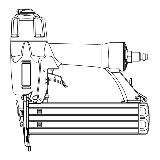
- Page 29 Fig. 1 A - Adjustable exhaust (escape ajustable) B - Trigger (gatillo) C - Quick-connect air fitting (conexión de aire de conexión rápida) D - Depth of drive adjustment (ajuste de la profundidad de introducción) E - Jam release (soltador) F - No-mar nosepiece (almohadilla protectora) G - Workpiece contact (disparador de contacto) H - Reload indicator (indicador de agotamiento...
- Page 30 Fig. 7 Fig. 10 A - Nail track (riel de los clavos) A - Latch (pestillo) Fig. 11 Fig. 8 A - Trigger (gatillo) B - Workpiece contact (disparador de contacto) Fig. 9 A - Jam release (soltador) B - Latch (pestillo) A - Drive depth adjustment (ajuste de la profundidad de introducción) B - To decrease depth (para disminuir la...
- Page 31 NOTES / NOTES / NOTAS...
- Page 32 MANUAL DEL OPERADOR 18 GAUGE BRAD NAILER CALIBRE 18, CLAvADORA DE PUNTILLAS H200BND • SERVICE Now that you have purchased your tool, should a need ever exist for repair parts or service, simply contact your nearest Authorized Service Center. Be sure to provide all pertinent facts when you call or visit. Please call 1-866-340-3912 for your nearest Authorized Service Center.
Need help?
Do you have a question about the H200BND and is the answer not in the manual?
Questions and answers